EP0347764B1 - Einrichtung zum Messen des Drehmomentes einer durch einen Stellantrieb bewegbaren Armatur - Google Patents
Einrichtung zum Messen des Drehmomentes einer durch einen Stellantrieb bewegbaren Armatur Download PDFInfo
- Publication number
- EP0347764B1 EP0347764B1 EP89110945A EP89110945A EP0347764B1 EP 0347764 B1 EP0347764 B1 EP 0347764B1 EP 89110945 A EP89110945 A EP 89110945A EP 89110945 A EP89110945 A EP 89110945A EP 0347764 B1 EP0347764 B1 EP 0347764B1
- Authority
- EP
- European Patent Office
- Prior art keywords
- torque
- actuator
- drive
- armature
- spindle
- Prior art date
- Legal status (The legal status is an assumption and is not a legal conclusion. Google has not performed a legal analysis and makes no representation as to the accuracy of the status listed.)
- Expired - Lifetime
Links
- 238000000034 method Methods 0.000 claims description 2
- 230000004907 flux Effects 0.000 claims 1
- 238000011156 evaluation Methods 0.000 description 2
- 238000012423 maintenance Methods 0.000 description 2
- 238000005259 measurement Methods 0.000 description 2
- 230000003449 preventive effect Effects 0.000 description 2
- 230000001681 protective effect Effects 0.000 description 2
- 230000001419 dependent effect Effects 0.000 description 1
- 238000013461 design Methods 0.000 description 1
- 230000009347 mechanical transmission Effects 0.000 description 1
- 238000011017 operating method Methods 0.000 description 1
- 230000000737 periodic effect Effects 0.000 description 1
- 230000036316 preload Effects 0.000 description 1
Images
Classifications
-
- G—PHYSICS
- G01—MEASURING; TESTING
- G01L—MEASURING FORCE, STRESS, TORQUE, WORK, MECHANICAL POWER, MECHANICAL EFFICIENCY, OR FLUID PRESSURE
- G01L5/00—Apparatus for, or methods of, measuring force, work, mechanical power, or torque, specially adapted for specific purposes
- G01L5/0061—Force sensors associated with industrial machines or actuators
-
- F—MECHANICAL ENGINEERING; LIGHTING; HEATING; WEAPONS; BLASTING
- F16—ENGINEERING ELEMENTS AND UNITS; GENERAL MEASURES FOR PRODUCING AND MAINTAINING EFFECTIVE FUNCTIONING OF MACHINES OR INSTALLATIONS; THERMAL INSULATION IN GENERAL
- F16K—VALVES; TAPS; COCKS; ACTUATING-FLOATS; DEVICES FOR VENTING OR AERATING
- F16K37/00—Special means in or on valves or other cut-off apparatus for indicating or recording operation thereof, or for enabling an alarm to be given
- F16K37/0025—Electrical or magnetic means
- F16K37/0041—Electrical or magnetic means for measuring valve parameters
-
- G—PHYSICS
- G01—MEASURING; TESTING
- G01L—MEASURING FORCE, STRESS, TORQUE, WORK, MECHANICAL POWER, MECHANICAL EFFICIENCY, OR FLUID PRESSURE
- G01L3/00—Measuring torque, work, mechanical power, or mechanical efficiency, in general
- G01L3/02—Rotary-transmission dynamometers
- G01L3/04—Rotary-transmission dynamometers wherein the torque-transmitting element comprises a torsionally-flexible shaft
- G01L3/10—Rotary-transmission dynamometers wherein the torque-transmitting element comprises a torsionally-flexible shaft involving electric or magnetic means for indicating
- G01L3/108—Rotary-transmission dynamometers wherein the torque-transmitting element comprises a torsionally-flexible shaft involving electric or magnetic means for indicating involving resistance strain gauges
Definitions
- the invention relates to a device for measuring the torque of a spindle of a fitting that can be moved by an actuator using at least one strain gauge.
- Measuring devices have so far been used to measure torques on fittings, which measure the force to be transmitted with the aid of load cells which are equipped with strain gauges.
- the structural design and the resulting size is not suitable for permanently leaving this measuring device between the valve and the actuator or electric motor of the actuator, so that these measuring devices can only be used for periodic measurements.
- a torque-dependent shutdown to protect the valve from overload is known.
- the worm shaft of the actuator is designed as a sliding worm, which is held in the center of the worm wheel via tension springs. If a load torque occurs on the drive shaft that is greater than the torque set by the preload of the springs, it presses Circumferential force on the worm wheel, the worm shaft from its central position and actuates the associated torque button via a lever system, which switches off the motor electrically.
- a mechanical control unit is complex and prone to failure because of the large number of mechanical transmission elements.
- reaction torque transducer which is mainly used for tightening screws. It consists of two flanges connected to each other by a torsion tube.
- CH-PS 463 145 an arrangement of coaxial hub elements is known, which allow a deflection of the power flow to a chain drive.
- One of the hubs is designed as a measuring hub.
- the invention has for its object to provide a device of the type mentioned, which is permanently installed and allows a continuous torque measurement during an adjustment movement of the valve stem.
- the housing of the actuator and the housing of the fitting are connected to one another to form a stationary structural unit via a flange bushing known per se in its cylindrical part as a torsion tube, in that a wall of the torsion tube weakened by a free rotation carries the strain gauges that the flange bushing is penetrated by the valve stem, and that in an annular space between the flange bushing and the valve stem, an adapter for transmitting the driving forces between the actuator and a threaded sleeve that adjusts the valve stem in the axial direction is arranged, the stationary during an adjustment movement of the valve stem arranged flange bushing is subjected to a torque measured in the form of a torsional moment, which corresponds to the reaction force for the flow of force between the actuator (3), adapter (16) and threaded sleeve (18).
- the flange bushing which is arranged in a stationary manner between the actuator and the valve, is subjected to a torsional moment that is measured via a strain gauge.
- a strain gauge By continuously measuring the torque, mechanical changes in the actuator / valve assembly can be recognized at an early stage by comparing changing torque curves under the same operating conditions. Preventive maintenance is thus possible before the unforeseen failure can cause major damage to a technical system.
- the measured torque values are used directly to control the electric motor of the actuator, so that a complex mechanical torque limiter is not required.
- the device can also be used to control process sequences with changing operating parameters. In the case of a flow control valve, for example, a changing torque can indicate a change in viscosity or flow.
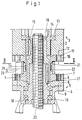
- flange bushing 1 shows a flange bushing 1, which is connected to a housing 2 of an actuator 3, not shown in more detail, and a housing 4 of a fitting 5, also not shown, to form a stationary structural unit.
- the lower flange 6 is provided with threaded bores 7 for receiving one each passing through the housing 4 and a ring 8 assigned to it, with nine, indicated, screws.
- the upper flange 10 has through bores 11 for receiving screws indicated by 12, which engage in threaded bores of the housing 2, not shown.
- the central drive column 14 which is supported on the housing 2 via a ball bearing 13, engages in a sleeve-shaped adapter 16 via a tongue and groove connection 15.
- the threaded sleeve 18, which is supported by ball bearings 19, is rotated via a further tongue and groove connection 17 between the adapter 16 and a threaded sleeve 18 of the armature 5, so that the spindle 20 of the armature 5 executes its stroke movement.
- the spindle 20 passes through the sleeve-shaped adapter 16.
- the flange bushing 1 is provided between its flanges 6, 10 with a free rotation 21, so that a relatively thin wall 22 remains at this point.
- This thin wall 22 carries two diametrically opposite strain gauges 23. They measure a torque occurring in the form of a torsional moment, which corresponds to a reaction force formed between the central drive column 14, adapter 16 and threaded sleeve 18.
- the measuring signals of the strain gauges are fed to a measuring amplifier indicated by 24.
- the output signal passes from the measuring amplifier to an evaluation station (not shown) and / or to a control unit (not shown) of the actuator motor. In the evaluation station, the torque curves with target curves of certain operating procedures compared to the actuator / valve assembly.
- Deviations provide information about mechanical changes in the unit and allow z.
- B. preventive maintenance The signals flowing to the control unit of the electric motor for the actuator lead to the motor being switched off when a permissible torque is exceeded.
- a protective sleeve 25 engages over the free rotation 21 and carries a housing 26 of the measuring amplifier 24.
- a seal 27 protects the strain gauges 23 arranged in the area of the free rotation 21 against dirt and / or damage.
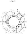
- FIG. 2 shows in a section along the line II-II of FIG. 1 the position of the strain gauges 23 and the measuring amplifier 24.
Landscapes
- Engineering & Computer Science (AREA)
- General Engineering & Computer Science (AREA)
- Physics & Mathematics (AREA)
- General Physics & Mathematics (AREA)
- Mechanical Engineering (AREA)
- Chemical & Material Sciences (AREA)
- Analytical Chemistry (AREA)
- Electrically Driven Valve-Operating Means (AREA)
- Indication Of The Valve Opening Or Closing Status (AREA)
- Force Measurement Appropriate To Specific Purposes (AREA)
- Measurement Of The Respiration, Hearing Ability, Form, And Blood Characteristics Of Living Organisms (AREA)
- Details Of Spanners, Wrenches, And Screw Drivers And Accessories (AREA)
Description
- Die Erfindung betrifft eine Einrichtung zum Messen des Drehmomentes einer durch einen Stellantrieb bewegbaren Spindel einer Armatur unter Verwendung wenigstens eines Dehnungsmeßstreifens.
- Zur Messung von Drehmomenten an Armaturen werden bisher Meßeinrichtungen verwendet, welche die zu übertragende Kraft mit Hilfe von Wägezellen messen, die mit Dehnungsmeßstreifen bestückt sind. Der konstruktive Aufbau und die daraus resultierende Baugröße ist nicht geeignet, diese Meßeinrichtung zwischen Armatur und Stellantrieb bzw. Elektromotor des Stellantriebes permanant zu belassen, so daß diese Meßeinrichtungen nur zu periodischen Messungen einsetzbar sind.
- Ferner ist aus der DE-PS 22 50 141 und der DE-AS 12 21 517 eine drehmomentabhängige Abschaltung zum Schutz der Armatur vor Überlast bekannt. Dabei ist die Schneckenwelle des Stellantriebes als Verschiebeschnecke ausgebildet, die über Spannfedern mittig zum Schneckenrad gehalten ist. Tritt an der Antriebswelle ein Lastmoment auf, das größer ist als das durch die Vorspannung der Federn eingestellte Moment, drückt die Umfangskraft am Schneckenrad die Schneckenwelle aus ihrer Mittellage und betätigt über ein Hebelsystem den dazugehörigen Drehmomenttaster, der den Motor elektrisch abschaltet. Eine solche mechanische Steuereinheit ist aufwendig und wegen der Vielzahl mechanischer Übertragungselemente störanfällig.
- In der DE-OS 35 28 364 wird ein Reaktionsdrehmomentaufnehmer beschrieben, der vorwiegend zum Anziehen von Schrauben verwendet wird. Er besteht aus zwei über ein Torosionsrohr miteinander verbundenen Flanschen.
- Weiterhin ist aus der CH-PS 463 145 eine Anordnung aus koaxialen Nabenelemente bekannt, die eine Umlenkung des Kraftflusses zu einem Kettentrieb ermöglichen. Eine der Naben ist als Meßnabe ausgebildet.
- Die Erfindung stellt sich die Aufgabe, eine Einrichtung der eingangs genannten Art anzugeben, die permanent eingebaut ist und während einer Verstellbewegung der Armaturenspindel eine kontinuierliche Drehmomentmessung erlaubt.
- Gelöst wird diese Aufgabe erfindungsgemäß dadurch, daß das Gehäuse des Stellantriebes und das Gehäuse der Armatur über eine in ihrem zylindrischen Teil als Torsionsrohr wirkende an sich bekannte Flanschbuchse miteinander zu einer stationären Baueinheit verbunden sind, daß eine durch eine Freidrehung geschwächte Wand des Torsionsrohres den Dehnungsmeßstreifen trägt, daß die Flanschbuchse von der Armaturenspindel durchsetzt ist, und daß in einem Ringraum zwischen der Flanschbuchse und der Armaturenspindel ein Adapter zur Übertragung der Antriebskräfte zwischen dem Stellantrieb und einer die Armaturenspindel in axialer Richtung verstellenden Gewindehülse angeordnet ist, wobei während einer Verstellbewegung der Armaturenspindel die stationär angeordnete Flanschbuchse einen über den Dehnungsmeßstreifen gemessenen, in form eines Torsionsmomentes auftretenden Drehmoment, ausgesetzt ist, das der Reaktionskraft zum Kraftfluß zwischen Stellantrieb (3), Adapter (16) und Gewindehülse (18) entspricht.
- Während der Kraftfluß über einen Adapter vom Stellantrieb zu einer die Armaturenspindel verstellenden Gewindebuchse gelangt, wird die zwischen Stellantrieb und Armatur stationär angeordnete Flanschbuchse einem Torsionsmoment ausgesetzt, das über einen Dehnungsmeßstreifen gemessen wird. Durch die kontinuerliche Messung des Drehmomentes können mechanische Veränderungen in der Baueinheit Stellantrieb/Armatur durch den Vergleich von sich ändernden Drehmomentkurven bei gleichen Betriebszuständen frühzeitig erkannt werden. Eine vorbeugende Instandhaltung ist dadurch möglich, bevor der unvorhergesehene Ausfall große Schäden an einer technischen Anlage hervorrufen kann. Die Drehmomentmeßwerte werden unmittelbar zur Ansteuerung des Elektromotors des Stellantriebes verwendet, so daß ein aufwendiger mechanischer Drehmomentbegrenzer nicht erforderlich ist. Die Einrichtung läßt sich ferner zum Steuern von Verfahrensabläufen bei veränderlichen Betriebsparametern einsetzen. So kann beispielsweise bei einer Durchflußregelarmatur ein sich änderndes Drehmoment auf eine Viskositäts- oder Durchflußänderung hinweisen.
- Anhand von einem Ausführungsbeispiel und den Figuren 1 und 2 werden die erfindungsgemäßen Einrichtungen beschrieben.
- Dabei zeigt die
- Figur 1
- einen Längsschnitt durch einen Teilbereich von Stellantrieb und Armatur mit der dieselben verbindenden Flanschbuchse,
- Figur 2
- einen Schnitt entlang der Linie II-II der Figur 1.
- Die Figur 1 zeigt eine Flanschbuchse 1, die mit einem Gehäuse 2 eines nicht näher dargestellten Stellantriebes 3 und einem Gehäuse 4 einer ebenfalls nicht weiter dargestellten Armatur 5 zu einer stationären Baueinheit verbunden ist. Dazu ist der untere Flansch 6 mit Gewindebohrungen 7 zur Aufnahme von je einer das Gehäuse 4 und einen ihm zugeordneten Ring 8 durchsetzenden, mit neun, angedeuteten, Schraube versehen. Der obere Flansch 10 weist Druchgangsbohrungen 11 zur Aufnahme von mit 12 angedeuteten Schrauben auf, die in nicht dargestellte Gewindebohrungen des Gehäuses 2 eingreifen.
- Zur Übertragung der Antriebskraft des Stellantriebes 3 greift dessen über ein Kugellager 13 am Gehäuse 2 abgestützte Zentralantriebssäule 14 über eine Nut-/Federverbindung 15 in einen hülsenförmigen Adapter 16 ein. Über eine weitere Nut/Federverbindung 17 zwischen dem Adapter 16 und einer Gewindehülse 18 der Armatur 5 wird die durch Kugellager 19 abgestützte Gewindehülse 18 in Drehung versetzt, so daß die Spindel 20 der Armatur 5 ihre Hubbewgung ausführt. Dabei durchsetzt die Spindel 20 den hülsenförmigen Adapter 16.
- Die Flanschbuchse 1 ist zwischen ihren Flanschen 6, 10 mit einer Freidrehung 21 versehen, so daß an dieser Stelle eine relativ dünne wand 22 stehenbleibt. Diese dünne Wand 22 trägt zwei diametral gegenüberliegende Dehnungsmeßstreifen 23. Sie messen ein in Form eines Torsionsmomentes auftretendes Drehmoment, das einer den Kraftfluß zwischen Zentralantriebssäule 14, Adapter 16 und Gewindehülse 18 gebildeten Reaktionskraft entspricht. Die meßsignale der Dehnungsmeßstreifen werden einem mit 24 angedeuteten Meßverstärker zugeleitet. Vom Meßverstärker gelangt das Ausgangssignal zu einer nicht dargestellten Auswertestation und/oder zu einer nicht dargestellten Steuereinheit des Stellantriebs-Motor. In der Auswertestation werden die Drehmomentkurven mit Sollkurven bestimmter Betriebsabläufe der Baueinheit Stellantrieb/Armatur verglichen. Abweichungen geben Aufschluß über mechanische Veränderungen in der Baueinheit und erlauben z. B. eine vorbeugende Instandhaltung. Die der Steuereinheit des Elektromotors für den Stellantrieb zufließenden Signale führen zum Abschalten des Motors beim Überschreiten eines zulässigen Drehmomentes. Eine Schutzhülse 25 übergreift die Freidrehung 21 und trägt ein Gehäuse 26 des Meßverstärkers 24. Eine Dichtung 27 schützt die im Bereich der Freidrehung 21 angeordneten Dehnungsmeßstreifen 23 vor Verschmutzung und/oder Beschädigung.
- Die Figur 2 zeigt in einem Schnitt entlang der Linie II-II der Figur 1 die Position der Dehnungsmeßstreifen 23 und des Meßverstärkers 24. Die ein Scharnier 28 und ein Verschlußelement 29 aufweisende Schutzhülse 25 umfaßt konzentrisch die Wand 22 und trägt das Gehäuse 26 des Meßverstärkers 24.
Claims (2)
- Einrichtung zum Messen des Drehmomentes einer durch einen Stellantrieb (3) bewegbaren Spindel (20) einer Armatur (5) unter Verwendung wenigstens eines Dehnungsmeßstreifens (23), dadurch gekennnzeichnet, daß das Gehäuse (2) des Stellantriebes (3) und das Gehäuse (4) der Armatur (5) über eine in ihrem zylindrischen Teil als Torsionsrohr wirkende an sich bekannte Flanschbuchse (1) miteinander zu einer stationären Baueinheit verbunden sind, daß eine durch eine Freidrehung (21) geschwächte Wand (22) des Torsionsrohres den Dehnungsmeßstreifen (23) trägt, daß die Flanschbuchse von der Armaturenspindel (20) durchsetzt ist, und daß in einem Ringraum zwischen der Flanschbuchse (1) und der Armaturenspindel (20) ein Adapter (16) zur Übertragung der Antriebskräfte zwischen dem Stellantrieb (3) und einer die Armaturenspindel (20) in axialer Richtung verstellenden Gewindehülse (18) angeordnet ist, wobei während einer Verstellbewegung der Armaturenspindel die stationär angeordnete Flanschbuchse (1) einem über den Dehnungsstreifen gemessenen, in form eines Torsionsmomentes auftretenden Drehmoment, ausgesetzt ist, das der Reaktionskraft zum Kraftfluß zwischen Stellantrieb (3), Adapter (16) und Gewindehülse (18) entspricht.
- Verwendung einer Einrichtung nach Anspruch 1 zum Steuern von Verfahrensabläufen technischer Anlagen.
Priority Applications (1)
| Application Number | Priority Date | Filing Date | Title |
|---|---|---|---|
| EP92118593A EP0536806B1 (de) | 1988-06-21 | 1989-06-16 | Einrichtung zum Messen des Drehmomentes einer durch einen Stellantrieb bewegbaren Armatur |
Applications Claiming Priority (2)
| Application Number | Priority Date | Filing Date | Title |
|---|---|---|---|
| DE3820838A DE3820838A1 (de) | 1988-06-21 | 1988-06-21 | Einrichtung zum messen des drehmomentes einer durch einen stellantrieb bewegbaren armatur |
| DE3820838 | 1988-06-21 |
Related Child Applications (1)
| Application Number | Title | Priority Date | Filing Date |
|---|---|---|---|
| EP92118593.0 Division-Into | 1989-06-16 |
Publications (3)
| Publication Number | Publication Date |
|---|---|
| EP0347764A2 EP0347764A2 (de) | 1989-12-27 |
| EP0347764A3 EP0347764A3 (en) | 1990-12-19 |
| EP0347764B1 true EP0347764B1 (de) | 1996-06-05 |
Family
ID=6356873
Family Applications (2)
| Application Number | Title | Priority Date | Filing Date |
|---|---|---|---|
| EP92118593A Expired - Lifetime EP0536806B1 (de) | 1988-06-21 | 1989-06-16 | Einrichtung zum Messen des Drehmomentes einer durch einen Stellantrieb bewegbaren Armatur |
| EP89110945A Expired - Lifetime EP0347764B1 (de) | 1988-06-21 | 1989-06-16 | Einrichtung zum Messen des Drehmomentes einer durch einen Stellantrieb bewegbaren Armatur |
Family Applications Before (1)
| Application Number | Title | Priority Date | Filing Date |
|---|---|---|---|
| EP92118593A Expired - Lifetime EP0536806B1 (de) | 1988-06-21 | 1989-06-16 | Einrichtung zum Messen des Drehmomentes einer durch einen Stellantrieb bewegbaren Armatur |
Country Status (5)
| Country | Link |
|---|---|
| US (1) | US4977782A (de) |
| EP (2) | EP0536806B1 (de) |
| JP (1) | JP2692959B2 (de) |
| DE (4) | DE3820838A1 (de) |
| ES (2) | ES2072682T3 (de) |
Families Citing this family (32)
| Publication number | Priority date | Publication date | Assignee | Title |
|---|---|---|---|---|
| JPH03276463A (ja) * | 1990-03-26 | 1991-12-06 | Matsushita Electric Ind Co Ltd | オーディオビデオシステム |
| US5142906A (en) * | 1990-07-09 | 1992-09-01 | Westinghouse Electric Corp. | Apparatus for measuring valve stem loads in a motor operated valve assembly |
| US5220843A (en) * | 1991-07-26 | 1993-06-22 | Portland General Electric Corporation | In situ method of determining the thrust on valve components |
| JP2558361Y2 (ja) * | 1991-11-06 | 1997-12-24 | 株式会社明電舎 | トルク検出器 |
| SE469671B (sv) * | 1992-02-18 | 1993-08-16 | Asea Brown Boveri | Mekanisk koppling mellan en drivkaella och ett belastningsobjekt anordnad foer applicering av en vridmomentmaetande anordning |
| GB2274714A (en) * | 1993-02-02 | 1994-08-03 | Keystone Valve | Strain measuring device |
| US5469737A (en) * | 1993-12-20 | 1995-11-28 | Westinghouse Electric Corporation | Method and apparatus for measuring the axial load and position of a valve stem |
| US5454273A (en) * | 1994-02-09 | 1995-10-03 | Westinghouse Electric Corporation | Motor operated valve actuator diagnostic system and test stand |
| US5931044A (en) * | 1995-01-19 | 1999-08-03 | T&R Solutions, Inc. | Torque/position transducer |
| US5722286A (en) * | 1995-01-19 | 1998-03-03 | T & R Solutions, Inc. | Torque/position transducer |
| US5524485A (en) * | 1995-01-19 | 1996-06-11 | Southern Valve Service, Inc. | Torque/position transducer |
| JP4010374B2 (ja) * | 1995-03-24 | 2007-11-21 | 日本ギア工業株式会社 | 弁装置の負荷検出装置 |
| DE19512238A1 (de) * | 1995-03-31 | 1996-10-02 | Istec Gmbh | Verfahren zur Überwachung und zum Betrieb von insbesondere motorgetriebenen Armaturen |
| FR2733026B1 (fr) * | 1995-04-13 | 1997-05-09 | Gec Alsthom Velan | Boite a butees d'une vanne a obturateur, vanne a obturateur pourvue d'une telle boite a butees, procede d'etalonnage d'une telle vanne |
| DE19515130A1 (de) * | 1995-04-25 | 1996-10-31 | Werner & Pfleiderer | Einrichtung zur Messung des Drehmomenteintrages bei Mehrwellenextrudern |
| DE19609981A1 (de) * | 1996-03-14 | 1997-09-18 | Dietrich Gerhard Ellsaesser | Innenlager für Fahrräder mit integriertem Meßaufnahmesystem für Drehmoment, Drehzahl, Drehwinkel und Antriebsenergie |
| DE29607207U1 (de) * | 1996-04-20 | 1997-08-21 | Wagner, Paul-Heinz, 53804 Much | Hydraulischer Kraftschrauber |
| DE19623741A1 (de) | 1996-06-14 | 1997-12-18 | Wittenstein Motion Contr Gmbh | Einrichtung zur Erfassung und Auswertung der auf einen Spindeltrieb einwirkenden Betriebskraft |
| DE19936293A1 (de) * | 1999-08-02 | 2001-02-15 | Hbm Mes Und Systemtechnik Gmbh | Drehmomentsensor |
| FR2814237B1 (fr) * | 2000-09-15 | 2002-11-15 | Bosch Gmbh Robert | Dispositif de mesure sans fil de l'effort exerce dans une tige mobile axialament |
| DE10106625A1 (de) * | 2001-02-13 | 2002-08-29 | Staiger Mohilo & Co Gmbh | Drehmomentsensor |
| DE102007005894A1 (de) * | 2006-06-14 | 2007-12-20 | GIF Gesellschaft für Industrieforschung mbH | Drehmomentmessflansch |
| DE102008005580A1 (de) * | 2008-01-22 | 2009-08-06 | Tomas Flimel | Verfahren und Vorrichtung zur Überwachung ferngesteuerter Armaturen |
| FR2993954B1 (fr) * | 2012-07-26 | 2014-08-01 | Electricite De France | Vanne motorisee comportant une douille instrumentee. |
| FR3013099B1 (fr) * | 2013-11-08 | 2015-12-18 | Electricite De France | Vanne a ecrou de manoeuvre instrumente |
| DE102014019546B3 (de) | 2014-12-23 | 2016-05-04 | Samson Aktiengesellschaft | Federkörper für einen Kraftaufnehmer, wie Drehmoment- und/oder Zugkraft-/Druckkraftmesszelle |
| CN105092127B (zh) * | 2015-09-21 | 2018-07-03 | 北京中车重工机械有限公司 | 旋挖钻机扭矩检测装置和旋挖钻机扭矩检测方法 |
| CN105258833B (zh) * | 2015-09-25 | 2017-08-04 | 南京航空航天大学 | 爬壁动物仿圆柱面攀爬力学与行为测试系统 |
| DE102016114285B4 (de) | 2016-08-02 | 2025-01-30 | Samson Aktiengesellschaft | Flanschträger zum gegenseitigen Tragen einer Stellarmatur und eines Stellantriebs und Messeinrichtung |
| JP2021089239A (ja) * | 2019-12-05 | 2021-06-10 | アズビル株式会社 | トルクセンサ |
| CA3163447A1 (en) | 2020-01-03 | 2021-07-08 | Bray International, Inc. | Valve with load cell |
| CN116511996A (zh) * | 2023-06-15 | 2023-08-01 | 西南交通大学 | 一种钻削过程模拟及检测装置、检测方法 |
Family Cites Families (16)
| Publication number | Priority date | Publication date | Assignee | Title |
|---|---|---|---|---|
| DE1231517B (de) * | 1964-04-25 | 1966-12-29 | Siebeck Metallwerk G M B H | Motorischer Stellantrieb fuer Ventile od. dgl. mit Schneckengetriebe |
| CH463145A (de) * | 1966-10-31 | 1968-09-30 | Fischer Ag Georg | Drehmoment-Messnabe |
| GB1266973A (de) * | 1969-08-22 | 1972-03-15 | ||
| DE2250141C3 (de) * | 1972-10-13 | 1975-07-24 | Andrei Dmitriewitsch Leningrad Plotnikow | Schutzeinrichtung fur den elektromotorischen Antrieb einer Absperreinrichtung |
| DE2340582A1 (de) * | 1973-08-10 | 1975-02-20 | Zahnradfabrik Friedrichshafen | Vorrichtung zum uebertragen eines speisestromes in drehmoment-messnaben |
| JPS55169371U (de) * | 1979-05-23 | 1980-12-05 | ||
| DE3014873C2 (de) * | 1980-04-17 | 1983-03-24 | Samson Ag, 6000 Frankfurt | Verfahren und Vorrichtung zur Stellungsrückführung eines mittels eines Wärmemotors gesteuerten Stellgliedes, insbesondere eines Ventils für Heizungsanlagen |
| DE3212946A1 (de) * | 1982-04-07 | 1983-11-03 | Harald 6233 Kelkheim Matschin | Drehmomentmessystem |
| US4496286A (en) * | 1983-07-18 | 1985-01-29 | J-W Operating Company | Control system for engine-driven compressor unit and method of operation thereof |
| US4660416A (en) * | 1983-07-19 | 1987-04-28 | Charbonneau And Godfrey Associates | Motor operated valve analysis and testing system with monitoring of spring pack movement through side by side monitoring device |
| DE3507409A1 (de) * | 1985-03-02 | 1986-09-04 | Brown, Boveri & Cie Ag, 6800 Mannheim | Anordnung zur drehmomenterfassung an antriebsketten |
| DE3528364A1 (de) * | 1985-08-07 | 1987-02-19 | Helmut Erb Elektr Messtechnik | Reaktionsdrehmomentaufnehmer und verfahren zu seiner messbereichsanpassung |
| US4724711A (en) * | 1985-09-03 | 1988-02-16 | Aisin Seiki Kabushiki Kaisha | Torque detector |
| US4741227A (en) * | 1986-06-19 | 1988-05-03 | 501 Kubota, Ltd. | Tractor transmission to permit smooth change of speed operation effectuated by rotational resistance |
| US4741217A (en) * | 1987-04-06 | 1988-05-03 | Eaton Corporation | Magnetic field coupling circuit and rotary transducer using same |
| US4879901A (en) * | 1987-08-20 | 1989-11-14 | Liberty Technology Center, Inc. | System for evaluating the condition and performance of a valve and valve operator combination |
-
1988
- 1988-06-21 DE DE3820838A patent/DE3820838A1/de not_active Ceased
- 1988-06-21 DE DE8816363U patent/DE8816363U1/de not_active Expired
-
1989
- 1989-06-16 ES ES92118593T patent/ES2072682T3/es not_active Expired - Lifetime
- 1989-06-16 DE DE58909686T patent/DE58909686D1/de not_active Expired - Fee Related
- 1989-06-16 ES ES89110945T patent/ES2090025T3/es not_active Expired - Lifetime
- 1989-06-16 DE DE58909148T patent/DE58909148D1/de not_active Expired - Fee Related
- 1989-06-16 EP EP92118593A patent/EP0536806B1/de not_active Expired - Lifetime
- 1989-06-16 EP EP89110945A patent/EP0347764B1/de not_active Expired - Lifetime
- 1989-06-19 JP JP1156621A patent/JP2692959B2/ja not_active Expired - Lifetime
- 1989-06-21 US US07/369,471 patent/US4977782A/en not_active Expired - Fee Related
Non-Patent Citations (1)
| Title |
|---|
| ABB Reaktor Prüfbericht GBRA021921 "Drehmomentmessung an Armaturen",ABB Reaktor GmbH * |
Also Published As
| Publication number | Publication date |
|---|---|
| EP0347764A2 (de) | 1989-12-27 |
| DE58909686D1 (de) | 1996-07-11 |
| DE3820838A1 (de) | 1990-01-04 |
| US4977782A (en) | 1990-12-18 |
| EP0347764A3 (en) | 1990-12-19 |
| ES2072682T3 (es) | 1995-07-16 |
| DE58909148D1 (de) | 1995-05-04 |
| DE8816363U1 (de) | 1989-10-05 |
| EP0536806A1 (de) | 1993-04-14 |
| ES2090025T3 (es) | 1996-10-16 |
| JP2692959B2 (ja) | 1997-12-17 |
| JPH0287034A (ja) | 1990-03-27 |
| EP0536806B1 (de) | 1995-03-29 |
Similar Documents
| Publication | Publication Date | Title |
|---|---|---|
| EP0347764B1 (de) | Einrichtung zum Messen des Drehmomentes einer durch einen Stellantrieb bewegbaren Armatur | |
| EP4095017B1 (de) | Lenkaktuator für ein lenksystem und lenksystem für ein kraftfahrzeug | |
| EP0164574B1 (de) | Schrauber | |
| EP0042548B1 (de) | Schraubvorrichtung mit Drehmomentermittlung | |
| EP0599083B1 (de) | Antriebseinheit zur Steuerung und Regelung von Armaturen od.dgl. | |
| EP0699508B1 (de) | Hydro-Impulsschrauber insbesondere zum Anziehen von Schraubverbindungen | |
| DE10003633C2 (de) | Elektrische Servolenkvorrichtung | |
| DE2734182C3 (de) | Vorrichtung zum Messen von Lenkmomenten und Lenkwinkeln bei Fahrzeugen | |
| EP0482360A2 (de) | Motorgetriebene Presse mit Kraft- und Wegsensoren | |
| EP0060991A1 (de) | Vorrichtung zum Messen der Axialkraft in einer mittels Rollenlagern gelagerten Welle | |
| DE69407802T2 (de) | Elektrisch angetriebene lenkeinrichtung | |
| DE10329293A1 (de) | Einrichtung zur Erfassung einer Drehbewegung in einer Fahrzeug-Lenkeinrichtung | |
| DE19717290A1 (de) | Vorrichtung zur Drehmomentmessung | |
| EP0053357A1 (de) | Drehmoment-Messgerät | |
| DE2501521A1 (de) | Messeinrichtung fuer lenkungswerte von fahrzeugen, insbesondere kraftfahrzeugen | |
| DE3711925A1 (de) | Drehmomentdetektor | |
| EP2980551B1 (de) | Kraftfahrzeug-bremsprüfstand | |
| DE9312303U1 (de) | Vorrichtung zum Anziehen von Schraubverbindungen | |
| DE60109237T2 (de) | Elektrische Servolenkeinrichtung für ein Kraftfahrzeug | |
| DE3402501A1 (de) | Schrauber | |
| BE1031577B1 (de) | Lenkaktuator für ein Lenksystem eines Kraftfahrzeugs und Verfahren zum Betrieb eines Lenkaktuators | |
| DE19720325C1 (de) | Kraftmeßeinrichtung in einem Stellantrieb zur Steuerung von Armaturen | |
| DE19623741A1 (de) | Einrichtung zur Erfassung und Auswertung der auf einen Spindeltrieb einwirkenden Betriebskraft | |
| DE102007037969B4 (de) | Werkzeugvorrichtung | |
| DE4443781C1 (de) | Elektrische Servolenkung mit Sicherheitseinrichtung |
Legal Events
| Date | Code | Title | Description |
|---|---|---|---|
| PUAI | Public reference made under article 153(3) epc to a published international application that has entered the european phase |
Free format text: ORIGINAL CODE: 0009012 |
|
| AK | Designated contracting states |
Kind code of ref document: A2 Designated state(s): BE CH DE ES FR GB LI NL SE |
|
| PUAL | Search report despatched |
Free format text: ORIGINAL CODE: 0009013 |
|
| AK | Designated contracting states |
Kind code of ref document: A3 Designated state(s): BE CH DE ES FR GB LI NL SE |
|
| 17P | Request for examination filed |
Effective date: 19910124 |
|
| 17Q | First examination report despatched |
Effective date: 19911129 |
|
| GRAH | Despatch of communication of intention to grant a patent |
Free format text: ORIGINAL CODE: EPIDOS IGRA |
|
| GRAA | (expected) grant |
Free format text: ORIGINAL CODE: 0009210 |
|
| AK | Designated contracting states |
Kind code of ref document: B1 Designated state(s): BE CH DE ES FR GB LI NL SE |
|
| XX | Miscellaneous (additional remarks) |
Free format text: TEILANMELDUNG 92118593.0 EINGEREICHT AM 16/06/89. |
|
| ET | Fr: translation filed | ||
| REF | Corresponds to: |
Ref document number: 58909686 Country of ref document: DE Date of ref document: 19960711 |
|
| GBT | Gb: translation of ep patent filed (gb section 77(6)(a)/1977) |
Effective date: 19960627 |
|
| REG | Reference to a national code |
Ref country code: ES Ref legal event code: FG2A Ref document number: 2090025 Country of ref document: ES Kind code of ref document: T3 |
|
| REG | Reference to a national code |
Ref country code: ES Ref legal event code: FG2A Ref document number: 2090025 Country of ref document: ES Kind code of ref document: T3 |
|
| PLBI | Opposition filed |
Free format text: ORIGINAL CODE: 0009260 |
|
| PLBF | Reply of patent proprietor to notice(s) of opposition |
Free format text: ORIGINAL CODE: EPIDOS OBSO |
|
| 26 | Opposition filed |
Opponent name: SIEMENS AG Effective date: 19970304 |
|
| NLR1 | Nl: opposition has been filed with the epo |
Opponent name: SIEMENS AG |
|
| PLBF | Reply of patent proprietor to notice(s) of opposition |
Free format text: ORIGINAL CODE: EPIDOS OBSO |
|
| PGFP | Annual fee paid to national office [announced via postgrant information from national office to epo] |
Ref country code: FR Payment date: 19980415 Year of fee payment: 10 |
|
| PGFP | Annual fee paid to national office [announced via postgrant information from national office to epo] |
Ref country code: GB Payment date: 19980416 Year of fee payment: 10 |
|
| PGFP | Annual fee paid to national office [announced via postgrant information from national office to epo] |
Ref country code: SE Payment date: 19980507 Year of fee payment: 10 |
|
| PGFP | Annual fee paid to national office [announced via postgrant information from national office to epo] |
Ref country code: BE Payment date: 19980527 Year of fee payment: 10 |
|
| PGFP | Annual fee paid to national office [announced via postgrant information from national office to epo] |
Ref country code: ES Payment date: 19980629 Year of fee payment: 10 |
|
| RDAH | Patent revoked |
Free format text: ORIGINAL CODE: EPIDOS REVO |
|
| APAC | Appeal dossier modified |
Free format text: ORIGINAL CODE: EPIDOS NOAPO |
|
| APAE | Appeal reference modified |
Free format text: ORIGINAL CODE: EPIDOS REFNO |
|
| APAC | Appeal dossier modified |
Free format text: ORIGINAL CODE: EPIDOS NOAPO |
|
| PG25 | Lapsed in a contracting state [announced via postgrant information from national office to epo] |
Ref country code: GB Free format text: LAPSE BECAUSE OF NON-PAYMENT OF DUE FEES Effective date: 19990616 |
|
| PG25 | Lapsed in a contracting state [announced via postgrant information from national office to epo] |
Ref country code: ES Free format text: THE PATENT HAS BEEN ANNULLED BY A DECISION OF A NATIONAL AUTHORITY Effective date: 19990617 |
|
| PG25 | Lapsed in a contracting state [announced via postgrant information from national office to epo] |
Ref country code: SE Free format text: THE PATENT HAS BEEN ANNULLED BY A DECISION OF A NATIONAL AUTHORITY Effective date: 19990629 |
|
| PG25 | Lapsed in a contracting state [announced via postgrant information from national office to epo] |
Ref country code: FR Free format text: THE PATENT HAS BEEN ANNULLED BY A DECISION OF A NATIONAL AUTHORITY Effective date: 19990630 Ref country code: BE Free format text: LAPSE BECAUSE OF NON-PAYMENT OF DUE FEES Effective date: 19990630 |
|
| BERE | Be: lapsed |
Owner name: ABB REAKTOR G.M.B.H. Effective date: 19990630 |
|
| GBPC | Gb: european patent ceased through non-payment of renewal fee |
Effective date: 19990616 |
|
| EUG | Se: european patent has lapsed |
Ref document number: 89110945.6 |
|
| REG | Reference to a national code |
Ref country code: FR Ref legal event code: ST |
|
| REG | Reference to a national code |
Ref country code: ES Ref legal event code: FD2A Effective date: 20010604 |
|
| APAC | Appeal dossier modified |
Free format text: ORIGINAL CODE: EPIDOS NOAPO |
|
| PLBO | Opposition rejected |
Free format text: ORIGINAL CODE: EPIDOS REJO |
|
| PLBN | Opposition rejected |
Free format text: ORIGINAL CODE: 0009273 |
|
| STAA | Information on the status of an ep patent application or granted ep patent |
Free format text: STATUS: OPPOSITION REJECTED |
|
| PGFP | Annual fee paid to national office [announced via postgrant information from national office to epo] |
Ref country code: NL Payment date: 20020513 Year of fee payment: 14 Ref country code: CH Payment date: 20020513 Year of fee payment: 14 |
|
| 27O | Opposition rejected |
Effective date: 20020324 |
|
| NLR2 | Nl: decision of opposition | ||
| PGFP | Annual fee paid to national office [announced via postgrant information from national office to epo] |
Ref country code: DE Payment date: 20021227 Year of fee payment: 15 |
|
| PG25 | Lapsed in a contracting state [announced via postgrant information from national office to epo] |
Ref country code: LI Free format text: LAPSE BECAUSE OF NON-PAYMENT OF DUE FEES Effective date: 20030630 Ref country code: CH Free format text: LAPSE BECAUSE OF NON-PAYMENT OF DUE FEES Effective date: 20030630 |
|
| PG25 | Lapsed in a contracting state [announced via postgrant information from national office to epo] |
Ref country code: NL Free format text: LAPSE BECAUSE OF NON-PAYMENT OF DUE FEES Effective date: 20040101 |
|
| REG | Reference to a national code |
Ref country code: CH Ref legal event code: PL |
|
| NLV4 | Nl: lapsed or anulled due to non-payment of the annual fee |
Effective date: 20040101 |
|
| PG25 | Lapsed in a contracting state [announced via postgrant information from national office to epo] |
Ref country code: DE Free format text: LAPSE BECAUSE OF NON-PAYMENT OF DUE FEES Effective date: 20050101 |
|
| APAH | Appeal reference modified |
Free format text: ORIGINAL CODE: EPIDOSCREFNO |