EP0347645A2 - Surveillance d'une pluralité de paramètres de procédés identiques - Google Patents
Surveillance d'une pluralité de paramètres de procédés identiques Download PDFInfo
- Publication number
- EP0347645A2 EP0347645A2 EP89110293A EP89110293A EP0347645A2 EP 0347645 A2 EP0347645 A2 EP 0347645A2 EP 89110293 A EP89110293 A EP 89110293A EP 89110293 A EP89110293 A EP 89110293A EP 0347645 A2 EP0347645 A2 EP 0347645A2
- Authority
- EP
- European Patent Office
- Prior art keywords
- sample
- monitoring
- sensor
- evaluating result
- samples
- Prior art date
- Legal status (The legal status is an assumption and is not a legal conclusion. Google has not performed a legal analysis and makes no representation as to the accuracy of the status listed.)
- Withdrawn
Links
Images
Classifications
-
- G—PHYSICS
- G06—COMPUTING OR CALCULATING; COUNTING
- G06F—ELECTRIC DIGITAL DATA PROCESSING
- G06F11/00—Error detection; Error correction; Monitoring
- G06F11/30—Monitoring
-
- G—PHYSICS
- G05—CONTROLLING; REGULATING
- G05B—CONTROL OR REGULATING SYSTEMS IN GENERAL; FUNCTIONAL ELEMENTS OF SUCH SYSTEMS; MONITORING OR TESTING ARRANGEMENTS FOR SUCH SYSTEMS OR ELEMENTS
- G05B23/00—Testing or monitoring of control systems or parts thereof
- G05B23/02—Electric testing or monitoring
- G05B23/0205—Electric testing or monitoring by means of a monitoring system capable of detecting and responding to faults
- G05B23/0218—Electric testing or monitoring by means of a monitoring system capable of detecting and responding to faults characterised by the fault detection method dealing with either existing or incipient faults
- G05B23/0224—Process history based detection method, e.g. whereby history implies the availability of large amounts of data
- G05B23/0227—Qualitative history assessment, whereby the type of data acted upon, e.g. waveforms, images or patterns, is not relevant, e.g. rule based assessment; if-then decisions
- G05B23/0237—Qualitative history assessment, whereby the type of data acted upon, e.g. waveforms, images or patterns, is not relevant, e.g. rule based assessment; if-then decisions based on parallel systems, e.g. comparing signals produced at the same time by same type systems and detect faulty ones by noticing differences among their responses
Definitions
- the present invention relates to the monitoring of processes, particularly in installations where a large number of processes which are identical with respect to at least one process parameter are being performed.
- each process In many installations of this type, it is frequently necessary to monitor all of the ongoing processes, and the monitoring results are employed to derive diagnoses of the condition, or status, of each individual process. It may be desired, for example, to monitor at least one operating parameter of each process and to test or compare various measured parameters according to specified rules in order to arrive at diagnoses indicating the operating state of each process, and thus of the component or components controlling the process.
- These operations may be carried out in a digital computer in which each rule is constituted by a programming subroutine.
- Such a procedure is employed in diagnostic expert systems in which selected items of information relating to the processes are compared or combined according to specified rules in order to produce diagnostic information.
- diagnostic expert systems in which selected items of information relating to the processes are compared or combined according to specified rules in order to produce diagnostic information.
- a boiler may contain a waterwall composed of a large number of tubes through which water is flowing while being heated. These tubes are nominally identical in that they are all associated with the same flow and heat distribution conditions. The conditions in each tube may be monitored by a temperature sensor, as well as other components, and the output readings of each temperature sensor must be examined as part of an overall monitoring and diagnostic system.
- Known expert systems interpret sensor readings and combine the interpreted readings from various sensors to produce diagnoses of the operating conditions of components and subsystems of the apparatus being monitored. These operations are carried out according to various rules which provide indications, inter alia, of the validity of the sensor readings or the level of confidence in the sensor readings, measures of belief and disbelief in the resulting diagnosis, the severity, importance and priority of malfunction diagnosis, etc.
- each set of instructions must be provided for implementing each rule associated with each sensor output evaluation and each diagnostic step.
- Each set of instructions is generally provided in the form of a subroutine stored in memory. Since it has heretofore been the practice to provide a separate set of instructions for each rule which is to be applied to the output of each sensor, a con siderable amount of programming time must be employed and a considerable amount of memory capacity must be provided when a large number of identical processes are to be monitored.
- Another object of the invention is to substantially reduce the amount of memory capacity required in such a system.
- the invention in its broad form resides in method and a system for monitoring a plurality of processes (2) which are identical with respect to at least one process parameter, of the type employing a plurality of sensors each disposed for monitoring the one process parameter of a respective process, the sensors all having identical responses to the one process parameter, and using sampling means connected for deriving a succession of sensor response samples, each successive sample being associated with a respective sensor; characterizecd by succession monitoring means ( ⁇ 1 ⁇ 2 ⁇ 3) connected to said sampling means for receiving each sample in succession and for evaluating a predetermined characteristic of the sensor response represented by each sample, said monitoring means including a processing path having an input to which all samples are applied in series and having an output for providing an indication of the evaluating result for each sample; and diagnosing means ( ⁇ 4) connected for receiving and interpreting the indication of the evaluating result of each sample in order to provide an indication of the status of each process.
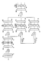
- the Figure illustrates, in the form of a block diagram, a system for implementing the simplified monitoring procedure according to the invention.
- This system could be of the dedicated, or hard-wired, type or it could be created by suitable programming of a general purpose digital computer, with each register shown in the Figure being constituted by a respective group of memory locations.
- the illustrated system is connected to monitor a large number, for example 900, of boiler waterwall temperature sensors whose outputs 2 are monitored repetitively during successive time frames, each frame being of duration T.
- Each sensor may, typically, be a temperature monitoring thermocouple.
- each frame T the signals on all of the outputs 2 are applied in succession via a time multiplexer 4 to an analog/digital converter 6.
- the signal on each sensor output 2 is supplied to converter 6 during a respective time slot, t, having a duration such that the number of time slots t in each frame T is equal to the number of temperature sensors. If the sensors produce digital outputs, converter 6 can be eliminated
- Each digitized sensor output sample is then conducted from converter 6 via a time demultiplexer 8 to a respective cell, or memory location, of a register 10 which stores the digital representation of the output reading of a respective thermocouple sensor.
- a register 10 which stores the digital representation of the output reading of a respective thermocouple sensor.
- Each cell of register 10 has an output line connected to a respective input of a time multiplexer 14 which supplies the digital values stored in the cells of register 10 in succession to a monitoring unit 18 which tests each digital value according to a given rule r1 which provides an indication of whether or not the reading being produced by each sensor is higher than a selected value corresponding to the upper range of the normal operating temperature.
- the resulting indication produced by unit 18 for the reading of each sensor is supplied via a time demultiplexer 20 to a respective cell, or memory location, of a further register 24, which constitutes a second array node.
- Unit 18 performs the same operation on each sensor reading stored in register 10, and thus implements the array rule r1 for testing all of the sensor readings.
- unit 18 can be constituted by a single set of instructions, or a single subroutine, which operates repetitively on successive output samples from the respective sensors.
- the serial output from multiplexer 14 is additionally supplied to the input of a delay member 28 which produces a time delay, T, equal to the frame interval, T.
- Delay member 28 could, for example, be a serial register having a number of stages equal to the number of time slots in each time frame.
- the output of delay member 28 is supplied, together with the output of multiplexer 14, to a second monitoring unit 30 which, during the period, t, of each time slot compares the values of the digital signals at its inputs according to a rule r2 and produces an indication whenever the value being supplied from multiplexer 14 exceeds that being supplied by delay member 28 by a predetermined amount. Since the two signals supplied at any given instant to unit 30 represent successive readings from the same sensor, unit 30 will produce an output signal indicative of whether the temperature reading of that sensor has risen sharply.
- this indication could also be based on a comparison of the readings produced by a given sensor over a time interval composed of a plurality of frame periods.
- delay member 28 would be constructed to produce a delay equal to nT, where n is a selected integer.
- Monitoring unit 30 can be constructed in a manner similar to unit 18 and thus implements a second array rule.
- the successive output indications produced by unit 30 are supplied, via a demultiplexer 32, to respective locations of a register 34, where they are temporarily stored.
- Register 34 constitutes a third array node.
- the output from multiplexer 14 is additionally applied simultaneously to one input of a third monitoring unit 38 and to the input of a second delay member 40 which delays signals arriving thereat by an interval, t, equal to the duration of one time slot, t, and which supplies the delayed signal to a second input of monitoring unit 38.
- Monitoring unit 38 thus receives, during each time slot, the sensor signal sample associated with that time slot and the sensor signal sample associated with the immediately preceding time slot.
- the two signal samples supplied to monitoring unit 38 are thus indicative of the temperature readings of two adjacent sensors at essentially the same point in time.
- Monitoring unit 38 is arranged to compare the temperature readings being produced by two adjacent sensors according to a rule r3 and to produce an output indication when the temperature reading of the sensor associated with a given time slot exceeds that of the sensor associated with the immediately preceding time slot by more than a selected threshold magnitude.
- the monitoring result produced by monitoring unit 38 is then supplied, via a demultiplexer 42, to a further register 44 having a plurality of memory locations each associated with a respective time slot, and thus with a respective sensor, register 44 constituting a fourth array node.
- the outputs of corresponding memory locations of registers 24, 34 and 44 are supplied via respective multiplexers 46, 48 and 50 to a diagnostic unit 52 which combines the outputs from memory locations associated with the same time slot, and thus the same sensor, according to a rule r4 and derives an output signal constituting an indication of the status of the boiler tube containing the sensor associated with that time slot.
- rule r4 when the temperature reading of a given sensor is higher than a selected upper limit, has risen sharply from the measurement produced during a preceding time slot and is higher than the reading of the sensor in the adjacent tube, rule r4 produces the conclusion that the associated tube is blocked and an indication to this effect is conducted via a demultiplexer 54 to a respective location of an output register 56, constituting a fifth array node, from which the fault indication associated with each boiler tube can be supplied to a higher diagnostic level and/or to an output display being monitored by plant personnel.
- Unit 52 could alternatively be configured to produce a fault signal when any two of the three inputs constitutes a fault indication.
- each of units 18, 30, 38 and 52 is constituted by a single set of instructions, or a subroutine, which is executed repetitively on the output sample from each sensor, each set of instructions defining a selected rule (r1, r2, r3, r4).
- a selected rule r1, r2, r3, r4
- the present invention can be applied to any other monitoring or diagnostic system in which the outputs from a substantial number of nominally identical sensors must be processed identically.
- any one of the monitoring units could be configured to perform various functions employed in expert diagnostic systems, such as the development of an indication of the degree of confidence in the particular sensor reading, which would cause the output produced by the particular monitoring unit to have a value which can vary over a certain range, and representations of measures of belief and disbelief in the resulting diagnosis, which could, for example, be reflected in the value of the indication signal appearing in each location of register 56.
- any known diagnostic tool can be incorporated into the programming or circuit structure constituting each monitoring unit.
- a diagnostic operation according to the disclosed example of the present invention can be carried out by processing the sensor readings derived during a given time frame in parallel in monitoring units 18, 30, and 38, with the processing in unit 52 being carried out during a subsequent time frame.
- the system illustrated in the Figure includes a plurality of intermediate storage registers 10, 24, 34 and 44 from which the various individual indications can be supplied to respective output devices. This might be of use if, for example, it is desired to separately monitor the operation of selected sensors or to verify the indications which contributed to a diagnosis.
- the invention could be implemented by a system from which all registers except output register 56 and all multiplexers and demultiplexers except for multiplexer 4 and demultiplexer 54 are eliminated.
- the output of converter 6 would be connected directly to the inputs of monitoring units 18, 30 and 38 and delay numbers 28 and 40, and the outputs of monitoring units 18, 30 and 38 would be connected directly to respective inputs of monitoring unit 52.
- This arrangement would represent a substantial structural simplification and would shorten the time between the sampling of a set of sensor readings and the derivation of a diagnostic indication since sensor output signal samples could then be supplied to elements 18, 28, 30, 38 and 40 during a first frame interval, and the output indications from units 18, 30 and 38 would be processed in unit 52 and be supplied to register 56 during the same frame interval or the next succeeding frame interval.
- each column is associated with a particular sensor and each row represents a different fact about that sensor.
- a first row would store the indication of the current sensor reading
- a second row an indication of whether that reading is abnormally high
- a third row the indication of the sensor reading during the preceding frame interval
- a fourth row an indication of whether the sensor temperature reading rose sharply
- a fifth row the indication of whether the sensor reading is higher than that of the adjacent sensor
- a sixth row the resulting indication of a conclusion as to whether the associated tube is blocked.
- each row would thus correspond to one of the registers illustrated in the Figure.
- appropriate locations of the matrix would be linked according to the respective rules to derive the desired indications.
- the first row would be linked to the second row according to rule r1
- the first and third rows would be linked to the fourth row according to rule r2
- the first row of that column and the first row of an adjacent column would be linked to the fifth row of that column according to rule r3
- the second, fourth and fifth rows would be linked to the sixth row according to rule r4.
- the indications associated with the sensors would be derived successively by providing, for each rule, a single set of instructions to which the indication or indications associated with each sensor are applied in turn.
- the provision of a single set of instructions for each rule minimizes the memory space required to store the instructions.
- the invention has been exemplified by an arrangement which evaluates the outputs of a plurality of sensors of one type, the invention could also be employed in further diagnostic levels where the outputs of different types of sensors are compared or correlated to perform other diagnostic functions.
- all sensors of a given type would be monitored in the manner described above and the results associated with different sensors associated with the same component or process would be multiplexed and supplied to an evaluation or diagnostic unit in a manner such that each such unit would receive information associated with a given component or process in time coincidence and would supply the resulting evaluation or diagnostic indication to a higher level diagnostic unit in the appropriate time sequence or, by demultiplexing, to a display or storage location associated with the particular component or process.
Landscapes
- Engineering & Computer Science (AREA)
- Physics & Mathematics (AREA)
- General Physics & Mathematics (AREA)
- Automation & Control Theory (AREA)
- Theoretical Computer Science (AREA)
- Quality & Reliability (AREA)
- General Engineering & Computer Science (AREA)
- Testing Or Calibration Of Command Recording Devices (AREA)
Applications Claiming Priority (2)
| Application Number | Priority Date | Filing Date | Title |
|---|---|---|---|
| US07/209,818 US4951234A (en) | 1988-06-22 | 1988-06-22 | Monitoring a plurality of identical process parameters |
| US209818 | 1988-06-22 |
Publications (2)
| Publication Number | Publication Date |
|---|---|
| EP0347645A2 true EP0347645A2 (fr) | 1989-12-27 |
| EP0347645A3 EP0347645A3 (fr) | 1992-08-12 |
Family
ID=22780429
Family Applications (1)
| Application Number | Title | Priority Date | Filing Date |
|---|---|---|---|
| EP19890110293 Withdrawn EP0347645A3 (fr) | 1988-06-22 | 1989-06-07 | Surveillance d'une pluralité de paramètres de procédés identiques |
Country Status (6)
| Country | Link |
|---|---|
| US (1) | US4951234A (fr) |
| EP (1) | EP0347645A3 (fr) |
| JP (1) | JP2835452B2 (fr) |
| KR (1) | KR0136785B1 (fr) |
| CN (1) | CN1039670A (fr) |
| CA (1) | CA1325279C (fr) |
Families Citing this family (12)
| Publication number | Priority date | Publication date | Assignee | Title |
|---|---|---|---|---|
| US5095417A (en) * | 1988-05-17 | 1992-03-10 | Kabushiki Kaisha Komatsu Seisakusho | Apparatus for carrying out serial control |
| US5237512A (en) * | 1988-12-02 | 1993-08-17 | Detector Electronics Corporation | Signal recognition and classification for identifying a fire |
| GB2231693A (en) * | 1989-05-08 | 1990-11-21 | Philips Electronic Associated | Data processing system |
| US5089978A (en) * | 1990-02-09 | 1992-02-18 | Westinghouse Electric Corp. | Automatic plant state diagnosis system including a display selection system for selecting displays responsive to the diagnosis |
| US5122976A (en) * | 1990-03-12 | 1992-06-16 | Westinghouse Electric Corp. | Method and apparatus for remotely controlling sensor processing algorithms to expert sensor diagnoses |
| JPH06251030A (ja) * | 1993-02-24 | 1994-09-09 | Hitachi Ltd | 都市ライフライン運用管理システム |
| US6363330B1 (en) | 1998-04-10 | 2002-03-26 | Satnam Singh Sampuran Alag | Thermocouple failure detection in power generation turbines |
| JP2001157906A (ja) | 1999-11-29 | 2001-06-12 | Toyota Motor Corp | 機械加工装置および機械加工方法 |
| JP2003242271A (ja) * | 2002-02-13 | 2003-08-29 | Toshiba Corp | プラント診断方法および診断システム |
| US20050096759A1 (en) * | 2003-10-31 | 2005-05-05 | General Electric Company | Distributed power generation plant automated event assessment and mitigation plan determination process |
| US20050260471A1 (en) * | 2004-05-18 | 2005-11-24 | Logan Victor W | Electrical current measurement in a fuel cell |
| US8275577B2 (en) * | 2006-09-19 | 2012-09-25 | Smartsignal Corporation | Kernel-based method for detecting boiler tube leaks |
Family Cites Families (6)
| Publication number | Priority date | Publication date | Assignee | Title |
|---|---|---|---|---|
| JPS5434501B2 (fr) * | 1974-02-15 | 1979-10-27 | ||
| JPS51124448A (en) * | 1975-04-23 | 1976-10-29 | Hitachi Ltd | Centralized supervisory system |
| EP0158192B1 (fr) * | 1984-03-31 | 1991-06-05 | B a r m a g AG | Méthode d'acquisition de données de mesure d'une pluralité de points de mesure |
| US4644479A (en) * | 1984-07-31 | 1987-02-17 | Westinghouse Electric Corp. | Diagnostic apparatus |
| US4718025A (en) * | 1985-04-15 | 1988-01-05 | Centec Corporation | Computer management control system |
| US4802094A (en) * | 1985-07-10 | 1989-01-31 | Hitachi, Ltd. | Process monitoring apparatus for process management in production and assembly lines |
-
1988
- 1988-06-22 US US07/209,818 patent/US4951234A/en not_active Expired - Fee Related
-
1989
- 1989-06-07 EP EP19890110293 patent/EP0347645A3/fr not_active Withdrawn
- 1989-06-16 CA CA000603036A patent/CA1325279C/fr not_active Expired - Fee Related
- 1989-06-22 JP JP1160597A patent/JP2835452B2/ja not_active Expired - Lifetime
- 1989-06-22 CN CN89104275A patent/CN1039670A/zh active Pending
- 1989-06-22 KR KR1019890008636A patent/KR0136785B1/ko not_active Expired - Fee Related
Also Published As
| Publication number | Publication date |
|---|---|
| JPH0261520A (ja) | 1990-03-01 |
| KR900000783A (ko) | 1990-01-31 |
| EP0347645A3 (fr) | 1992-08-12 |
| US4951234A (en) | 1990-08-21 |
| KR0136785B1 (ko) | 1998-06-15 |
| JP2835452B2 (ja) | 1998-12-14 |
| CN1039670A (zh) | 1990-02-14 |
| CA1325279C (fr) | 1993-12-14 |
Similar Documents
| Publication | Publication Date | Title |
|---|---|---|
| US4951234A (en) | Monitoring a plurality of identical process parameters | |
| DE3689800T2 (de) | Anlagen-Diagnosesystem. | |
| US7739067B2 (en) | In-service calibration of temperature measurement devices using plant monitoring system data | |
| US6598195B1 (en) | Sensor fault detection, isolation and accommodation | |
| US4630189A (en) | System for determining abnormal plant operation based on whiteness indexes | |
| EP1416348B1 (fr) | Procédé d'isolation et d'identification de fautes temporelles | |
| Luong et al. | Observability, redundancy, reliability and integrated design of measurement systems | |
| CN109779791A (zh) | 一种固体火箭发动机中异常数据智能诊断方法 | |
| KR101988397B1 (ko) | 발전소보호계통의 응답시간평가장치 및 방법 | |
| US20240055304A1 (en) | Method and device for optimizing an amount of testing with respect to a total test time | |
| Hines et al. | An evaluation of instrument calibration monitoring using artificial neural networks | |
| CN120977891B (zh) | 一种基于智能算力算法的电路封装测试系统及方法 | |
| JPH0621845B2 (ja) | プラントの総合予防保全システム | |
| DE112023000815T5 (de) | System und verfahren zur behebung einer nichteinhaltung der mindestverzögerungszeit nach der herstellung | |
| Pradana et al. | Software reliability growth model for FPGA-based safety critical software system | |
| Gonçalves et al. | Monitoring an experimental reactor using the group method of data handling approach | |
| JPS6277612A (ja) | プラント異常診断方法 | |
| JPS6022211A (ja) | 故障診断装置 | |
| JPH05149762A (ja) | 異常診断装置 | |
| Madron | Identification of gross errors in balance measurements | |
| JPH0797436B2 (ja) | 発電プラント過渡データ表示装置 | |
| TR2023001235A1 (tr) | Si̇ni̇r ağinin deakti̇ve edi̇lecek bi̇r nöronunu saptamak üzere bi̇r si̇ni̇r aği ve bi̇r i̇leti̇şi̇m bi̇ri̇mi̇ i̇çeren bi̇r i̇leti̇şi̇m si̇stemi̇ne sahi̇p araç | |
| CN118801674A (zh) | 一种振动台多功率模块并联均流控制方法及装置 | |
| JP3290221B2 (ja) | 分散階層形データ処理システム | |
| Repin et al. | Diagnostics of the information subsystem of an automatic process control system using artificial intelligence technologies |
Legal Events
| Date | Code | Title | Description |
|---|---|---|---|
| PUAI | Public reference made under article 153(3) epc to a published international application that has entered the european phase |
Free format text: ORIGINAL CODE: 0009012 |
|
| AK | Designated contracting states |
Kind code of ref document: A2 Designated state(s): BE CH DE ES FR GB IT LI SE |
|
| 17P | Request for examination filed |
Effective date: 19901228 |
|
| PUAL | Search report despatched |
Free format text: ORIGINAL CODE: 0009013 |
|
| AK | Designated contracting states |
Kind code of ref document: A3 Designated state(s): BE CH DE ES FR GB IT LI SE |
|
| STAA | Information on the status of an ep patent application or granted ep patent |
Free format text: STATUS: THE APPLICATION IS DEEMED TO BE WITHDRAWN |
|
| 18D | Application deemed to be withdrawn |
Effective date: 19940104 |