EP0347622A2 - Alimentation à découpage combinée au circuit de déviation horizontal dans un dispositif de reproduction d'image - Google Patents
Alimentation à découpage combinée au circuit de déviation horizontal dans un dispositif de reproduction d'image Download PDFInfo
- Publication number
- EP0347622A2 EP0347622A2 EP89109814A EP89109814A EP0347622A2 EP 0347622 A2 EP0347622 A2 EP 0347622A2 EP 89109814 A EP89109814 A EP 89109814A EP 89109814 A EP89109814 A EP 89109814A EP 0347622 A2 EP0347622 A2 EP 0347622A2
- Authority
- EP
- European Patent Office
- Prior art keywords
- voltage
- power supply
- winding
- picture tube
- transformer
- Prior art date
- Legal status (The legal status is an assumption and is not a legal conclusion. Google has not performed a legal analysis and makes no representation as to the accuracy of the status listed.)
- Withdrawn
Links
Images
Classifications
-
- H—ELECTRICITY
- H04—ELECTRIC COMMUNICATION TECHNIQUE
- H04N—PICTORIAL COMMUNICATION, e.g. TELEVISION
- H04N5/00—Details of television systems
- H04N5/63—Generation or supply of power specially adapted for television receivers
-
- H—ELECTRICITY
- H04—ELECTRIC COMMUNICATION TECHNIQUE
- H04N—PICTORIAL COMMUNICATION, e.g. TELEVISION
- H04N3/00—Scanning details of television systems; Combination thereof with generation of supply voltages
- H04N3/10—Scanning details of television systems; Combination thereof with generation of supply voltages by means not exclusively optical-mechanical
- H04N3/16—Scanning details of television systems; Combination thereof with generation of supply voltages by means not exclusively optical-mechanical by deflecting electron beam in cathode-ray tube, e.g. scanning corrections
- H04N3/18—Generation of supply voltages, in combination with electron beam deflecting
Definitions
- the invention relates to a switching power supply with a combined horizontal output stage circuit in image display devices with the features specified in the preamble of claim 1.
- Such a switching power supply from the European. Patents 090 085 and 133 980 of the applicant are known.
- the advantage of such a switching power supply is, in particular, that only a single transformer is required as a galvanic isolating point between the supply network and the chassis side, via whose chassis-side windings all the operating voltages required in the image display device can be obtained.
- the high voltage for the anode of the picture tube is generated in the known switching power supply either by using a high-voltage cascade connected to the high-voltage winding or by the high-voltage winding being designed as a split.
- DE-OS 29 44 220 discloses a line transformer for a television receiver with a primary side feeding the line deflection coils and a secondary side supplying the high voltage with two high-voltage rectifiers connected in series in the same direction.
- the primary and secondary sides each contain only one winding.
- the first rectifier lies between the first end of the high-voltage winding and ground and the second rectifier lies between the second end of the high-voltage winding and the anode of the picture tube.
- This circuit arrangement contains a high-voltage cascade, at the output of which a voltage divider connected to ground is arranged.
- the voltage divider consists of a total of 4 resistors and has a tap for the focusing voltage and one or more taps for one or more screen grid voltage (s) of the picture tube.
- German patent specification 27 19 146 it is known to connect the bleeder resistor and the focus regulator in series between the high-voltage connection of the picture tube and ground, the bleeder resistor being structurally combined with the high-voltage plug of the picture tube and the focus regulator being arranged on the picture tube base plate.
- German Patent 28 19 990 it is known from German Patent 28 19 990 to arrange the bleeder resistor and the focus regulator outside the encapsulated high-voltage cascade.
- the bleeder resistor consists of two resistors, the first of which is located in its own molded insulating housing either in the high-voltage cable or in the high-voltage connector of the picture tube, and the second is housed in a common housing with the focus controller.
- Patent specification 133 980 is the object of the invention to show a way in which the high voltage for the picture tube anode and the focusing voltage can be generated in a structurally simple manner, wherein it should be ensured that the heat generated in the bleeder resistor cannot lead to damage in the transformer.
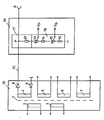
- the switching power supply shown contains a transformer 1, which has a primary winding 2 and a control winding 3 on the network side and a high-voltage winding 4 on the chassis side, a winding 5, via which a supply voltage for the horizontal output stage is generated, a winding 6 for a first low-voltage voltage (e.g. for the sound signal stages) and a winding 7 for a second low voltage (for example for vertical deflection).
- the circuits connected to the windings 2, 3, 5, 6 and 7 are not dealt with in more detail below, since their construction is fundamentally familiar to the person skilled in the art and is furthermore not necessary for understanding the invention.
- the cathode of a diode 9 is connected, the anode of which is connected to ground.
- the anode of a diode 8 is connected, at the cathode of which the desired high voltage is available.
- the main advantage of this type of high voltage generation is that At the two connections of the high-voltage winding 4, a voltage with different polarity is present in relation to ground and with blocked diodes. As a result, the voltage in the center of the winding is zero with respect to ground. This leads to a reduced interference radiation of the transformer compared to known arrangements. Furthermore, the high-voltage generating device described requires little space and comes - for example, in comparison to that from the European. Patents 090 085 and 133 980 known high-voltage generating devices - with few components.
- the entire transformer including the two diodes 8 and 9, is cast in a first casting compound, preferably epoxy resin.
- a first casting compound preferably epoxy resin.
- epoxy resin as potting compound is advantageous because the commercially available diodes are usually also potted in epoxy resin. If a different material was chosen as the potting compound for the transformer, undesirable vacuoles could result in unfavorable operating conditions (heat!) Due to the different expansion coefficients of the potting materials.
- the cathode of the diode 8 is connected to the anode A of the picture tube (not shown) via a high-voltage cable 11 via the picture tube base plate 19 of the picture display device.
- the high voltage cable 11 has a tap point P in the region of the picture tube base plate 19, which is connected to ground via a voltage divider 12, 13, 14, 15, 16.
- this voltage divider has the function of a bleeder resistor for discharging the picture tube anode to ground.
- the voltage divider is dimensioned such that a substantial part of the high anode voltage drops across a first resistor 12 of the voltage divider.
- the voltage divider is used to generate the focusing voltage.
- two further resistors 13 and 14 are connected to the first resistor 12, the resistor 13 having a tap for the focusing voltage U F.
- the voltage divider is used to generate one or more screen grid voltages for the picture tube.
- two further resistors 15 and 16 are connected to the resistor 14 of the focus regulator, the resistor 15 having a tap for a screen grid voltage U G.
- the resistor 16 of the screen grid regulator is connected to ground.
- All resistors of the voltage divider 12, 13, 14, 15, 16 are arranged in a common housing 17, 18 as a compact unit on the picture tube base plate 19.
- the resistor 12 is encapsulated within the common housing in a second potting compound 17.
- the resistors 13, 14, 15 and 16 are arranged outside the casting compound 17.
- the potting compound 17 is preferably made of silicone rubber, which has a greater elasticity than epoxy resin. This has the advantage that when the resistor 12 is heated, the likelihood that cracks occur in the material is greatly reduced.
- the heat generated in the bleeder resistor can in no way lead to the destruction of the high-voltage generation arrangement or the transformer. Diodes 8 and 9 would be particularly at risk. If the potting compound, in which the resistor 12 is located, is destroyed by overheating of the bleeder resistor, only the unit 17, 18 on the picture tube base plate needs to be replaced. Due to the gain of the focusing voltage and the screen grid voltage on the picture tube base plate, simple cable routing results. In particular, only a single cable connection is required from the transformer in the sealing compound 10, which is usually located on the device chassis, to the picture tube base plate 19, which is located in the immediate vicinity of the picture tube.
Landscapes
- Engineering & Computer Science (AREA)
- Multimedia (AREA)
- Signal Processing (AREA)
- Details Of Television Scanning (AREA)
- Coils Or Transformers For Communication (AREA)
Applications Claiming Priority (2)
| Application Number | Priority Date | Filing Date | Title |
|---|---|---|---|
| DE19883821113 DE3821113A1 (de) | 1988-06-23 | 1988-06-23 | Schaltnetzteil mit kombinierter horizontalendstufenschaltung in bildwiedergabegeraeten |
| DE3821113 | 1988-06-23 |
Publications (2)
| Publication Number | Publication Date |
|---|---|
| EP0347622A2 true EP0347622A2 (fr) | 1989-12-27 |
| EP0347622A3 EP0347622A3 (fr) | 1991-11-13 |
Family
ID=6357027
Family Applications (1)
| Application Number | Title | Priority Date | Filing Date |
|---|---|---|---|
| EP19890109814 Withdrawn EP0347622A3 (fr) | 1988-06-23 | 1989-05-31 | Alimentation à découpage combinée au circuit de déviation horizontal dans un dispositif de reproduction d'image |
Country Status (2)
| Country | Link |
|---|---|
| EP (1) | EP0347622A3 (fr) |
| DE (1) | DE3821113A1 (fr) |
Cited By (1)
| Publication number | Priority date | Publication date | Assignee | Title |
|---|---|---|---|---|
| EP0452860A3 (en) * | 1990-04-18 | 1992-12-23 | Sharp Kabushiki Kaisha | Facsimile apparatus comprising cordless telephone set |
Family Cites Families (3)
| Publication number | Priority date | Publication date | Assignee | Title |
|---|---|---|---|---|
| US3886434A (en) * | 1973-09-07 | 1975-05-27 | Warwick Electronics Inc | Flyback transformer |
| DE2832799C3 (de) * | 1978-07-07 | 1983-12-01 | Ernst Roederstein Spezialfabrik für Kondensatoren GmbH, 8300 Landshut | Baugruppe zur Hochspannungsversorgung einer Kathodenstrahlröhre mit Strahlfokussierung |
| DE3640732A1 (de) * | 1986-11-28 | 1988-06-09 | Standard Elektrik Lorenz Ag | Zeilentransformator |
-
1988
- 1988-06-23 DE DE19883821113 patent/DE3821113A1/de not_active Withdrawn
-
1989
- 1989-05-31 EP EP19890109814 patent/EP0347622A3/fr not_active Withdrawn
Cited By (1)
| Publication number | Priority date | Publication date | Assignee | Title |
|---|---|---|---|---|
| EP0452860A3 (en) * | 1990-04-18 | 1992-12-23 | Sharp Kabushiki Kaisha | Facsimile apparatus comprising cordless telephone set |
Also Published As
| Publication number | Publication date |
|---|---|
| EP0347622A3 (fr) | 1991-11-13 |
| DE3821113A1 (de) | 1989-12-28 |
Similar Documents
| Publication | Publication Date | Title |
|---|---|---|
| DE2228194C2 (de) | Spannungsregelschaltung | |
| DE2458302A1 (de) | Netzteil mit einem sperrwandler fuer einen fernsehempfaenger mit ultraschallfernbedienung | |
| EP0096778B1 (fr) | Microphone | |
| EP0180761B1 (fr) | Montage de circuit pour la déviation verticale des rayons électroniques dans des tubes cathodiques pour télévision | |
| DE3637015C2 (de) | Versorgungsschaltung für ein Videobildgerät | |
| DE3101848C2 (fr) | ||
| DE2633237A1 (de) | Einschalt-stromversorgungsschaltung fuer einen fernsehempfaenger | |
| DE2749847A1 (de) | Schaltnetzteil fuer einen rundfunkempfaenger, insbesondere einen fernsehempfaenger | |
| EP0347622A2 (fr) | Alimentation à découpage combinée au circuit de déviation horizontal dans un dispositif de reproduction d'image | |
| DE60310158T2 (de) | Leistungsversorgung | |
| DE910673C (de) | Anordnung zur Zufuehrung von Betriebsspannungen an Schaltungsteile, die gegenueber ihrer Umgebung hohe Wechselspannungen fuehren | |
| EP0766377B1 (fr) | Circuit d'alimentation de courant pour plusieurs amplificateurs de puissance | |
| DE4015461A1 (de) | Schaltung zum stabilisieren der hochspannung einer hochspannungsgeneratorschaltung einer kathodenstrahlroehre | |
| DE69516597T2 (de) | Fokussierspannungsversorgung für eine Kathodenstrahlröhre | |
| EP0066804B1 (fr) | Transformateur de lignes pour récepteur de télévision | |
| DE10246548A1 (de) | Verfahren und Einrichtung zur Elektronenbeschleunigung | |
| EP0358987B1 (fr) | Appareil de visualisation avec tube à rayons cathodiques et dispositif de mesure du courant de faisceaux | |
| DE1237699B (de) | Schaltungsanordnung zur Erzeugung einer einstellbaren Gleichspannung fuer eine Kathodenstrahlroehre | |
| DE1161308B (de) | Ablenkeinrichtung fuer Kathodenstrahlroehren | |
| DE3215143C2 (fr) | ||
| DE3817892C2 (de) | Hochspannungstransformator | |
| EP0405081B1 (fr) | Transformateur du type diode-split | |
| EP0263936A1 (fr) | Alimentation de puissance à commutation sur le circuit secondaire | |
| DE4112067A1 (de) | Leistungsversorgungseinrichtung fuer eine kathodenstrahlroehre | |
| DE3741845A1 (de) | Schaltung zum schutz der bildroehre |
Legal Events
| Date | Code | Title | Description |
|---|---|---|---|
| PUAI | Public reference made under article 153(3) epc to a published international application that has entered the european phase |
Free format text: ORIGINAL CODE: 0009012 |
|
| AK | Designated contracting states |
Kind code of ref document: A2 Designated state(s): AT CH DE FR GB IT LI |
|
| PUAL | Search report despatched |
Free format text: ORIGINAL CODE: 0009013 |
|
| AK | Designated contracting states |
Kind code of ref document: A3 Designated state(s): AT CH DE FR GB IT LI |
|
| STAA | Information on the status of an ep patent application or granted ep patent |
Free format text: STATUS: THE APPLICATION IS DEEMED TO BE WITHDRAWN |
|
| 18D | Application deemed to be withdrawn |
Effective date: 19920514 |