EP0346973A1 - Anordnung zum Aufzeichnen oder Wiedergeben eines elektrischen Signals auf einem magnetischen Aufzeichnungsträger - Google Patents
Anordnung zum Aufzeichnen oder Wiedergeben eines elektrischen Signals auf einem magnetischen Aufzeichnungsträger Download PDFInfo
- Publication number
- EP0346973A1 EP0346973A1 EP89201465A EP89201465A EP0346973A1 EP 0346973 A1 EP0346973 A1 EP 0346973A1 EP 89201465 A EP89201465 A EP 89201465A EP 89201465 A EP89201465 A EP 89201465A EP 0346973 A1 EP0346973 A1 EP 0346973A1
- Authority
- EP
- European Patent Office
- Prior art keywords
- signal
- time
- pair
- heads
- head
- Prior art date
- Legal status (The legal status is an assumption and is not a legal conclusion. Google has not performed a legal analysis and makes no representation as to the accuracy of the status listed.)
- Granted
Links
Images

Classifications
-
- G—PHYSICS
- G11—INFORMATION STORAGE
- G11B—INFORMATION STORAGE BASED ON RELATIVE MOVEMENT BETWEEN RECORD CARRIER AND TRANSDUCER
- G11B5/00—Recording by magnetisation or demagnetisation of a record carrier; Reproducing by magnetic means; Record carriers therefor
- G11B5/008—Recording on, or reproducing or erasing from, magnetic tapes, sheets, e.g. cards, or wires
-
- H—ELECTRICITY
- H04—ELECTRIC COMMUNICATION TECHNIQUE
- H04N—PICTORIAL COMMUNICATION, e.g. TELEVISION
- H04N1/00—Scanning, transmission or reproduction of documents or the like, e.g. facsimile transmission; Details thereof
- H04N1/21—Intermediate information storage
- H04N1/2104—Intermediate information storage for one or a few pictures
- H04N1/2112—Intermediate information storage for one or a few pictures using still video cameras
- H04N1/212—Motion video recording combined with still video recording
-
- G—PHYSICS
- G11—INFORMATION STORAGE
- G11B—INFORMATION STORAGE BASED ON RELATIVE MOVEMENT BETWEEN RECORD CARRIER AND TRANSDUCER
- G11B20/00—Signal processing not specific to the method of recording or reproducing; Circuits therefor
- G11B20/00007—Time or data compression or expansion
-
- G—PHYSICS
- G11—INFORMATION STORAGE
- G11B—INFORMATION STORAGE BASED ON RELATIVE MOVEMENT BETWEEN RECORD CARRIER AND TRANSDUCER
- G11B20/00—Signal processing not specific to the method of recording or reproducing; Circuits therefor
- G11B20/10—Digital recording or reproducing
- G11B20/18—Error detection or correction; Testing, e.g. of drop-outs
-
- G—PHYSICS
- G11—INFORMATION STORAGE
- G11B—INFORMATION STORAGE BASED ON RELATIVE MOVEMENT BETWEEN RECORD CARRIER AND TRANSDUCER
- G11B5/00—Recording by magnetisation or demagnetisation of a record carrier; Reproducing by magnetic means; Record carriers therefor
- G11B5/008—Recording on, or reproducing or erasing from, magnetic tapes, sheets, e.g. cards, or wires
- G11B5/00813—Recording on, or reproducing or erasing from, magnetic tapes, sheets, e.g. cards, or wires magnetic tapes
- G11B5/00847—Recording on, or reproducing or erasing from, magnetic tapes, sheets, e.g. cards, or wires magnetic tapes on transverse tracks
- G11B5/0086—Recording on, or reproducing or erasing from, magnetic tapes, sheets, e.g. cards, or wires magnetic tapes on transverse tracks using cyclically driven heads providing segmented tracks
- G11B5/00865—Recording on, or reproducing or erasing from, magnetic tapes, sheets, e.g. cards, or wires magnetic tapes on transverse tracks using cyclically driven heads providing segmented tracks for transducing on more than one segment simultaneously
- G11B5/00873—Recording on, or reproducing or erasing from, magnetic tapes, sheets, e.g. cards, or wires magnetic tapes on transverse tracks using cyclically driven heads providing segmented tracks for transducing on more than one segment simultaneously the segments being disposed in different longitudinal zones of the tape
-
- G—PHYSICS
- G11—INFORMATION STORAGE
- G11B—INFORMATION STORAGE BASED ON RELATIVE MOVEMENT BETWEEN RECORD CARRIER AND TRANSDUCER
- G11B5/00—Recording by magnetisation or demagnetisation of a record carrier; Reproducing by magnetic means; Record carriers therefor
- G11B5/48—Disposition or mounting of heads or head supports relative to record carriers ; arrangements of heads, e.g. for scanning the record carrier to increase the relative speed
- G11B5/52—Disposition or mounting of heads or head supports relative to record carriers ; arrangements of heads, e.g. for scanning the record carrier to increase the relative speed with simultaneous movement of head and record carrier, e.g. rotation of head
- G11B5/53—Disposition or mounting of heads on rotating support
- G11B5/531—Disposition of more than one recording or reproducing head on support rotating cyclically around an axis
-
- H—ELECTRICITY
- H04—ELECTRIC COMMUNICATION TECHNIQUE
- H04N—PICTORIAL COMMUNICATION, e.g. TELEVISION
- H04N1/00—Scanning, transmission or reproduction of documents or the like, e.g. facsimile transmission; Details thereof
- H04N1/21—Intermediate information storage
- H04N1/2104—Intermediate information storage for one or a few pictures
- H04N1/2112—Intermediate information storage for one or a few pictures using still video cameras
- H04N1/2137—Intermediate information storage for one or a few pictures using still video cameras with temporary storage before final recording, e.g. in a frame buffer
- H04N1/2141—Intermediate information storage for one or a few pictures using still video cameras with temporary storage before final recording, e.g. in a frame buffer in a multi-frame buffer
-
- H—ELECTRICITY
- H04—ELECTRIC COMMUNICATION TECHNIQUE
- H04N—PICTORIAL COMMUNICATION, e.g. TELEVISION
- H04N1/00—Scanning, transmission or reproduction of documents or the like, e.g. facsimile transmission; Details thereof
- H04N1/21—Intermediate information storage
- H04N1/2104—Intermediate information storage for one or a few pictures
- H04N1/2112—Intermediate information storage for one or a few pictures using still video cameras
- H04N1/215—Recording a sequence of still pictures, e.g. burst mode
-
- H—ELECTRICITY
- H04—ELECTRIC COMMUNICATION TECHNIQUE
- H04N—PICTORIAL COMMUNICATION, e.g. TELEVISION
- H04N5/00—Details of television systems
- H04N5/76—Television signal recording
- H04N5/78—Television signal recording using magnetic recording
- H04N5/782—Television signal recording using magnetic recording on tape
- H04N5/7824—Television signal recording using magnetic recording on tape with rotating magnetic heads
- H04N5/7826—Television signal recording using magnetic recording on tape with rotating magnetic heads involving helical scanning of the magnetic tape
Definitions
- the invention relates to an apparatus for recording an electric signal on a magnetic record carrier in tracks which are inclined relative to the longitudinal direction of said record carrier, and to an apparatus for reproducing a signal recorded by means of such a recording apparatus.
- European Patent Application 210,773 reveals a recording apparatus as defined in the opening paragraph, comprising - an input terminal for receiving the electric signal, - a signal separator having an input coupled to the input terminal, for dividing the electric signal into consecutive blocks having a specific length of time and for applying the consecutive blocks to a first and a second output in such a way that blocks having odd sequence numbers are applied to the first output and blocks having even sequence number are applied to the second output, - a time-base-correction circuit which is constructed to provide time compression or time-expansion of the consecutive blocks, to delay blocks having odd sequence number relative to those having even sequence number and to supply the two signals thus processed to a first and second output respectively, - at least one pair of write heads having different azimuth angles and arranged on a rotatable head drum, one write head of a pair being arranged to be coupled to the first output of the time-base-correction circuit and the other write head of the same pair being arranged to be coupled to the second output of the time-base-correcti
- the two write heads of a pair of write heads are regularly spaced along the drum circumference.
- the known apparatus can also be used as a reproducing apparatus, in which case it comprises - at least one pair of read heads having different azimuth angles, and arranged on a rotatable head drum, - a time-base-correction circuit having a first and a second input arranged to be coupled respectively to one read head and to the other read head of the pair of read heads, which correction circuit is constructed to provide a time compression or time expansion of the signal blocks applied to the first and the second input respectively, to delay the signal blocks applied to one input relative to those applied to the other input, - a signal-combination unit having a first and a second input and an output, for combining the signal blocks applied to the first and the second input in order to restore the electric signal and for feeding the electric signal to the output, which output is coupled to an output terminal for supplying the electric signal.
- the known apparatus has the disadvantage that during operation it produces a high acoustic noise level, that only very dimensional tolerances of the components are permissible, and that sometimes the reproduction quality is not satisfactory.
- the invention aims at mitigating these drawbacks and therefore proposes an apparatus for recording an electric signal which is characterized in that the write heads of a pair of write heads are are arranged close to each other and have a mechanically rigid coupling to each other, and in that the time base correction circuit is adapted to provide a time expansion or time compression of the signal blocks by a factor of ⁇ .n/180.(M+1), where ⁇ is the wrapping angle of the record carrier around the head drum and differs from 180 o , n is the number of head pairs, and M is the number of times within a specific time interval that a head pair which comes in contact with the record carrier during said time interval does not record a signal in the record carrier, which time interval is defined by those instants at which two consecutive track pairs are recorded by one or two head pairs.
- the apparatus for reproducing an electric signal is characterized in that the read heads of one pair of read heads are arranged close to each other and have a mechanically rigid coupling to each other, and in that the time-base-correction circuit is adapted to provide a time compression or time expansion of the signal blocks applied to the first and the second input by a factor of 180.(M+1)/ ⁇ .n, where ⁇ is the wrapping angle of the record carrier around the head drum and differs from 180 o , n is the number of head pairs and M is the number of times within a specific time interval that a head pair which comes in contact with the record carrier during said time interval does not read a signal from the record carrier, which two track pairs are read consecutively by one or two head pairs.
- the heads of one pair of read or write heads are arranged at one location on the head drum these heads hit against the record carrier only once every revolution of the head drum during recording and reproduction, which enables the acoustic noise level to be reduced.
- the tracks written by the two heads of one pair of heads are yet recorded parallel to each other on the record carrier. The tracks may then be warped.
- the apparatus comprises positioning means for positioning the head pair in a direction transverse to the track said tracks can still be read correctly.
- the positioning means are constructed as a dynamic tracking system only one actuator is needed, on which the pair of heads is arranged.
- the apparatus may be characterized further in that it comprises a second pair of write or read heads having different azimuth angles and arranged on the rotatable head drum, which heads are arranged close to each other and have a mechanically rigid coupling to each nother.
- An apparatus comprising two or more head pairs which are equidistantly spaced along the circumference enables information to be recorded or read at different tape speeds but with a constant speed of rotation of the head drum.
- An apparatus comprising two head pairs which are 180 o spaced apart on the head drum can record at the "normal" tape speed and at a tape speed which is twice as high.
- the information recorded by the second pair of write heads may comprise additional information, for example the finest detail of an encoded video picture or an entirely different signal, or it enables a higher resolution standard to be adopted.
- Recording or reading information at different tape speeds and constant speed of rotation of the head drum is also possible in the case of more than two pairs of write or read heads.
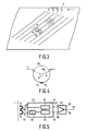
- Fig. 1 shows diagrammatically an apparatus for recording an electric signal, for example a digital video signal on a magnetic record carrier 1.
- the apparatus comprises an input terminal 2 to which the electric signal can be applied.
- the input terminal 2 is coupled to an input 3 of a signal separator 4.
- the signal separator is intended for dividing the electric signal applied to the input 3 into consecutive blocks of a specific length of time and for applying these consecutive blocks to a first output 5 and a second output. Blocks having odd sequence number are applied to the output 5. Blocks having even sequence numbers are applied to the output 6.
- the signal separator 4 may be constructed as a switch 18.
- a time-base-correction circuit 7 has two inputs 8 and 9 coupled to the respective output 5 and 6 of the separator 4 and two outputs 10 and 11 coupled to the write heads K1 and K2 respectively.
- the write heads K1 and K2 constitute a pair of heads having a mechanically rigid coupling to each other, see Figs. 3 and 4, and arranged close to each other at a location along the circumference of a head drum 40, see Fig. 4.
- the heads have different azimuth angles.
- the correction circuit 7 should provide a time expansion or compression of both signals by a factor of ⁇ .n/180.(M+1).
- the correction circuit 7 then comprises two expansion or compression units 13 and 14 respectively, which expand or compress the signals applied to the inputs 8 and 9 in time.
- the output 15 of the expansion/compression unit 13 is connected to the output 10 of the correction circuit 7 via a signal delay unit 16 in which the output signal of the unit 13 is delayed by a time interval ⁇ .
- the output 17 of the unit 14 is coupled to the output 11 of the correction circuit 7.
- the correction circuit 7 should compress the signals applied to the inputs 8 and 9 in time by a factor of ⁇ /180.
- the correction circuit 7 then comprises units 13 and 14 which provide a time compression of the signals. Conversely, if ⁇ is larger than 180 o the units 13 and 14 will provide a time expansion of the signals.
- the signal separator 4 divides the signal into consecutive blocks B1, B2, B3, ... etc. of a specific length of time T. Blocks having odd sequence number are applied to the output 5.
- the switch 18 is then in the upper position. Blocks having even sequence numbers are applied to the output 6.
- the switch 18 is then in the lower position.
- the signals A1 and A2, see Figs. 2b and 2c respectively, are then available on the output 5 and 6 respectively. Since the wrapping angle ⁇ is larger than 180 o , see Fig.
- the signals A1 and A2 are time-expanded by a factor of ⁇ /180 in the units 13 and 14. This results in the signals A1′ and A2′ on the outputs 15 and 17, see Figs. 2d and 2e respectively.
- the signal A1′ is delayed by a time interval ⁇ , so that the signal A1 ⁇ , see Fig. 2f, is applied to the write head K1. Consequently, ⁇ is equal to T.
- the signal A2′ is applied to the write head K2.
- the blocks B1′ and B2′ are respectively recorded in tracks T1 and T2 on the record carrier 1 by the heads K1 and K2 respectively more or less concurrently, which depends on the positions of the heads relative to each other.
- the blocks B3′ and B4′ are respectively recorded in the tracks T3 and T4 by the heads K1 and K2 respectively substantially at the same time, see Fig. 3.
- the unit 7 only comprises the time delay means 16.
- Fig. 5 shows an apparatus for reading the electric signal from the record carrier 1 in Fig. 3.
- the apparatus comprises a pair of read heads K1 and K2, see Fig. 3, which have a mechanically rigid coupling with each other and which are arranged close to one another on a rotatable head drum 40. These heads are coupled to inputs 50 and 51 of a time base correction circuit 52. Two outputs 53 and 54 of the circuit 52 are coupled to inputs 55 and 56 respectively of a signal combination unit 57, which has an output 58 coupled to the output terminal 59.
- the wrapping angle ⁇ of the record carrier 1 around the head drum 40 is again assumed to be larger than 180 o , see Fig. 4.
- the apparatus shown in Fig. 5 should process the signal read from the record carrier 1 in a manner which is the inverse of the signal processing by means of the apparatus shown in Fig. 1. Since the heads K1 and K2 of the apparatus shown in Fig. 5 scan the same tracks as those recorded by the heads K1 and K2 of the apparatus shown in Fig. 1 this means that the signal A2′ read by the head K2 (from the tracks T2, T4, T6, ... etc.) should now be delayed by said time interval ⁇ . This is effected in the time delay unit 60 of the correction circuit 52.
- the correction circuit further comprises time-compression units 61 and 62 in which the signals read by the heads K1 and K2 are time-compressed.
- the signals A1 and A2 have been compressed during recording because the wrapping angle ⁇ is smaller than 180 o , the signals read from the record carrier will have to be expanded in the units 61 and 62 in order to recover the original signal.
- An apparatus in accordance with the invention comprising one pair of closely spaced heads with a mechanically rigid coupling is also capable of reading record carriers recorded by means of the present RDAT recorders.
- RDAT recorders have two heads which are arranged diametrally opposite one another on the head drum.
- the record carrier is wrapped around the head drum through an angle of 90 o or 135 o .
- the constructional parameters and the channel electronics can be the same because the bit rate of the signal which is effectively recorded in fact remain the same.
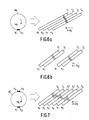
- Fig. 6a again shows the track pattern as recorded on the record carrier 1 by the apparatus shown in Fig. 1 at a normal tape speed V0. If it is assumed that the tape speed has been twice as high, the same information, i.e. the complete signal A in Fig. 2a, will be recorded on the record carrier by means of the heads K1 and K2 in a pattern as shown in Fig.6b. In fact, a spacing is now formed between the pairs of tracks T1, T2 and T3, T4 in which spacing additional information may be recorded. If the tape speed is 2V0, the spacing will be so large that exactly two tracks can be recorded on the record carrier by means of a second pair of rigidly mechanically coupled heads K3 and K4, see Fig. 7, which are arranged exactly opposite the first pair of heads K1, K2 on the head drum.
- Fig. 7 clearly shows that two tracks T1′, T2′ are recorded between the pairs of tracks T1, T2 and T3, T4 by means of the heads K3 and K4.
- the information recorded in the tracks T1′, T2′ is the additional information.
- This information may represent for example, the finest details of an encoded video picture or it enables a higher resolution standard to be used.
- a recording and/or reproducing apparatus comprising two pairs of heads can be operated in two ways.
- Each pair of heads again functions as described with reference to Figs. 1 to 5.
- the heads K1 and K2 record and/or read the information of Fig. 2a.
- the heads K3 and K4 record and/or read additional information as stated above.
- said one or more pairs of heads may each be provided with positioning means for positioning a pair of heads in a direction transverse to the tracks. This may mean that the tape transport is controlled in such a way that one pair of heads is positioned exactly at the appropriate adjacent tracks.
- positioning means for positioning a pair of heads in a direction transverse to the tracks. This may mean that the tape transport is controlled in such a way that one pair of heads is positioned exactly at the appropriate adjacent tracks.
- Another possibility is to arrange one pair of heads on a piezoelectric actuator and to control the piezoelectric actuator in such a way that the pair of heads is positioned exactly at the appropriate pair of adjacent tracks.
Landscapes
- Engineering & Computer Science (AREA)
- Signal Processing (AREA)
- Multimedia (AREA)
- Digital Magnetic Recording (AREA)
- Recording Or Reproducing By Magnetic Means (AREA)
- Television Signal Processing For Recording (AREA)
- Magnetic Record Carriers (AREA)
- Electrochromic Elements, Electrophoresis, Or Variable Reflection Or Absorption Elements (AREA)
- Paints Or Removers (AREA)
Priority Applications (1)
| Application Number | Priority Date | Filing Date | Title |
|---|---|---|---|
| AT89201465T ATE101447T1 (de) | 1988-06-14 | 1989-06-08 | Anordnung zum aufzeichnen oder wiedergeben eines elektrischen signals auf einem magnetischen aufzeichnungstraeger. |
Applications Claiming Priority (2)
| Application Number | Priority Date | Filing Date | Title |
|---|---|---|---|
| NL8801513A NL8801513A (nl) | 1988-06-14 | 1988-06-14 | Inrichting voor het opnemen of weergeven van een elektrisch signaal op/van een magnetische registratiedrager. |
| NL8801513 | 1988-06-14 |
Publications (2)
| Publication Number | Publication Date |
|---|---|
| EP0346973A1 true EP0346973A1 (de) | 1989-12-20 |
| EP0346973B1 EP0346973B1 (de) | 1994-02-09 |
Family
ID=19852457
Family Applications (1)
| Application Number | Title | Priority Date | Filing Date |
|---|---|---|---|
| EP89201465A Expired - Lifetime EP0346973B1 (de) | 1988-06-14 | 1989-06-08 | Anordnung zum Aufzeichnen oder Wiedergeben eines elektrischen Signals auf einem magnetischen Aufzeichnungsträger |
Country Status (8)
| Country | Link |
|---|---|
| US (2) | US5412515A (de) |
| EP (1) | EP0346973B1 (de) |
| JP (1) | JP2958332B2 (de) |
| KR (1) | KR0147064B1 (de) |
| AT (1) | ATE101447T1 (de) |
| DE (1) | DE68912972T2 (de) |
| ES (1) | ES2050214T3 (de) |
| NL (1) | NL8801513A (de) |
Cited By (2)
| Publication number | Priority date | Publication date | Assignee | Title |
|---|---|---|---|---|
| EP0486185A3 (en) * | 1990-11-16 | 1992-11-25 | Sony Corporation | Image signal recording apparatus and methods |
| WO1999030319A3 (en) * | 1997-12-08 | 1999-07-29 | Koninkl Philips Electronics Nv | Recording and reproduction of an information signal in a short play and a long play mode |
Families Citing this family (8)
| Publication number | Priority date | Publication date | Assignee | Title |
|---|---|---|---|---|
| NL8801513A (nl) * | 1988-06-14 | 1990-01-02 | Philips Nv | Inrichting voor het opnemen of weergeven van een elektrisch signaal op/van een magnetische registratiedrager. |
| US5392164A (en) * | 1990-05-25 | 1995-02-21 | Canon Kabushiki Kaisha | Dubbing system |
| KR0180922B1 (ko) * | 1993-10-15 | 1999-10-01 | 모리시타 요이찌 | 디지틀데이터기록방법 |
| EP0678854B1 (de) * | 1994-04-22 | 2001-11-28 | Deutsche Thomson-Brandt Gmbh | Verfahren zur Aufzeichnung eines digitalen Signals |
| ATE211596T1 (de) * | 1994-08-09 | 2002-01-15 | Koninkl Philips Electronics Nv | Gerät zur aufnahme und/oder wiedergabe von videosignalen und audiosignalen auf/von schrägspuren auf magnetband und magnetband für solch ein gerät |
| JPH08147611A (ja) * | 1994-11-25 | 1996-06-07 | Hitachi Ltd | 磁気記録再生方法および磁気記録再生装置 |
| WO1999028900A2 (en) | 1997-11-28 | 1999-06-10 | Koninklijke Philips Electronics N.V. | Recording and reproduction of a first signal with a first bitrate and a second information signal with a second bitrate larger than the first bitrate |
| EP2037686A3 (de) * | 2004-07-23 | 2010-09-22 | I-CES (Innovative Compression Engineering Solutions) | Kompressionsverfahren einer digitalen Audio-, Bild- oder Videodatei durch Entsynchronisierung |
Citations (8)
| Publication number | Priority date | Publication date | Assignee | Title |
|---|---|---|---|---|
| US4135205A (en) * | 1975-06-19 | 1979-01-16 | Sony Corporation | Skip field recorder with audio multiplexer |
| EP0049989A2 (de) * | 1980-10-03 | 1982-04-21 | Matsushita Electric Industrial Co., Ltd. | Video-Bandaufzeichnungs-Wiedergabegerät |
| DE3246062A1 (de) * | 1981-12-14 | 1983-06-16 | Sony Corp., Tokyo | Schraegspur-magnetband-aufzeichnungs/wiedergabe-einrichtung |
| GB2121229A (en) * | 1982-04-23 | 1983-12-14 | Sony Corp | Methods and apparatus for recording and reproducing information signals |
| EP0125051A2 (de) * | 1983-04-12 | 1984-11-14 | Victor Company Of Japan, Limited | Aufzeichnungs- und/oder Wiedergabegerät mit auf FM-Übersprechsignalkomponenten reagierendem Spurnachlaufservomechanismus |
| US4525750A (en) * | 1982-09-10 | 1985-06-25 | Rca Corporation | Automatic tracking system for multitrack recorders |
| US4556920A (en) * | 1982-12-10 | 1985-12-03 | Canon Kabushiki Kaisha | Reproduction device |
| EP0190919A2 (de) * | 1985-02-05 | 1986-08-13 | Sony Corporation | Aufzeichnungssystem |
Family Cites Families (8)
| Publication number | Priority date | Publication date | Assignee | Title |
|---|---|---|---|---|
| DE2908321C2 (de) * | 1979-03-03 | 1984-06-28 | Robert Bosch Gmbh, 7000 Stuttgart | Verfahren und Schaltungsanordnung zum Übertragen oder Speichern eines breitbandigen kontinuierlichen Signals in mehreren schmalbandigen Kanälen |
| JPS57202187A (en) * | 1981-06-08 | 1982-12-10 | Victor Co Of Japan Ltd | Magnetic recording and reproducing system for video signal |
| JP2625097B2 (ja) * | 1985-02-26 | 1997-06-25 | ソニー株式会社 | 広帯域信号の記録装置及び記録再生装置 |
| KR910001466B1 (ko) * | 1985-07-12 | 1991-03-07 | 마쯔시다덴기산교 가부시기가이샤 | 영상신호의 신호처리장치 |
| JPS62125502A (ja) * | 1985-11-27 | 1987-06-06 | Hitachi Ltd | 磁気記録再生装置 |
| JPS6457403A (en) * | 1987-08-27 | 1989-03-03 | Alps Electric Co Ltd | Rotary head type digital audio tape recorder |
| JPH01296401A (ja) * | 1988-05-24 | 1989-11-29 | Sony Corp | ヘリカルスキャン型記録装置 |
| NL8801513A (nl) * | 1988-06-14 | 1990-01-02 | Philips Nv | Inrichting voor het opnemen of weergeven van een elektrisch signaal op/van een magnetische registratiedrager. |
-
1988
- 1988-06-14 NL NL8801513A patent/NL8801513A/nl not_active Application Discontinuation
-
1989
- 1989-05-01 US US07/345,396 patent/US5412515A/en not_active Expired - Fee Related
- 1989-06-08 EP EP89201465A patent/EP0346973B1/de not_active Expired - Lifetime
- 1989-06-08 DE DE68912972T patent/DE68912972T2/de not_active Expired - Fee Related
- 1989-06-08 ES ES89201465T patent/ES2050214T3/es not_active Expired - Lifetime
- 1989-06-08 AT AT89201465T patent/ATE101447T1/de not_active IP Right Cessation
- 1989-06-08 JP JP1146523A patent/JP2958332B2/ja not_active Expired - Lifetime
- 1989-06-12 KR KR1019890008047A patent/KR0147064B1/ko not_active Expired - Fee Related
-
1995
- 1995-03-02 US US08/396,860 patent/US5495369A/en not_active Expired - Fee Related
Patent Citations (8)
| Publication number | Priority date | Publication date | Assignee | Title |
|---|---|---|---|---|
| US4135205A (en) * | 1975-06-19 | 1979-01-16 | Sony Corporation | Skip field recorder with audio multiplexer |
| EP0049989A2 (de) * | 1980-10-03 | 1982-04-21 | Matsushita Electric Industrial Co., Ltd. | Video-Bandaufzeichnungs-Wiedergabegerät |
| DE3246062A1 (de) * | 1981-12-14 | 1983-06-16 | Sony Corp., Tokyo | Schraegspur-magnetband-aufzeichnungs/wiedergabe-einrichtung |
| GB2121229A (en) * | 1982-04-23 | 1983-12-14 | Sony Corp | Methods and apparatus for recording and reproducing information signals |
| US4525750A (en) * | 1982-09-10 | 1985-06-25 | Rca Corporation | Automatic tracking system for multitrack recorders |
| US4556920A (en) * | 1982-12-10 | 1985-12-03 | Canon Kabushiki Kaisha | Reproduction device |
| EP0125051A2 (de) * | 1983-04-12 | 1984-11-14 | Victor Company Of Japan, Limited | Aufzeichnungs- und/oder Wiedergabegerät mit auf FM-Übersprechsignalkomponenten reagierendem Spurnachlaufservomechanismus |
| EP0190919A2 (de) * | 1985-02-05 | 1986-08-13 | Sony Corporation | Aufzeichnungssystem |
Cited By (4)
| Publication number | Priority date | Publication date | Assignee | Title |
|---|---|---|---|---|
| EP0486185A3 (en) * | 1990-11-16 | 1992-11-25 | Sony Corporation | Image signal recording apparatus and methods |
| US5229862A (en) * | 1990-11-16 | 1993-07-20 | Sony Corporation | Apparatus and method for recording image signals to allow reproduction at more than one data rate |
| WO1999030319A3 (en) * | 1997-12-08 | 1999-07-29 | Koninkl Philips Electronics Nv | Recording and reproduction of an information signal in a short play and a long play mode |
| AU755200B2 (en) * | 1997-12-08 | 2002-12-05 | Koninklijke Philips Electronics N.V. | Recording and reproduction of an information signal in a short play and a long play mode |
Also Published As
| Publication number | Publication date |
|---|---|
| EP0346973B1 (de) | 1994-02-09 |
| KR900000899A (ko) | 1990-01-31 |
| US5495369A (en) | 1996-02-27 |
| JP2958332B2 (ja) | 1999-10-06 |
| ES2050214T3 (es) | 1994-05-16 |
| JPH0244502A (ja) | 1990-02-14 |
| US5412515A (en) | 1995-05-02 |
| NL8801513A (nl) | 1990-01-02 |
| ATE101447T1 (de) | 1994-02-15 |
| DE68912972T2 (de) | 1994-07-28 |
| DE68912972D1 (de) | 1994-03-24 |
| KR0147064B1 (ko) | 1998-10-15 |
Similar Documents
| Publication | Publication Date | Title |
|---|---|---|
| US4410917A (en) | Method of and apparatus for recording information from a master medium onto a slave medium employing digital techniques | |
| US4685004A (en) | Rotary head type PCM recording and reproduction method and system | |
| US4473850A (en) | Method and apparatus for recording digitally coded television signals | |
| US5335116A (en) | Method and apparatus for recording analog video signal in compressed digital format | |
| US4852102A (en) | Interleave sequence method | |
| EP0092403B1 (de) | Verfahren und Anordnung zur Aufzeichnung und Wiedergabe von analogen Signalen | |
| EP0085517B1 (de) | Anordnung zur Aufzeichnung von digitalen Signalen | |
| EP0346973A1 (de) | Anordnung zum Aufzeichnen oder Wiedergeben eines elektrischen Signals auf einem magnetischen Aufzeichnungsträger | |
| GB2233489A (en) | Digital video signal recording method and apparatus | |
| EP0437316B1 (de) | Aufzeichnungsverfahren für digitale Signale und Gerät zur Aufzeichnung und Wiedergabe digitaler Signale | |
| US4549230A (en) | Redundantly and asynchronously recording an information signal | |
| US6456781B1 (en) | Recording and reproduction of a first signal with a first bit-rate and a second information signal with a second bit-rate larger than the first bit-rate | |
| EP0819307B1 (de) | Audio- und videodatenaufzeichnungs- und -wiedergabegerät und -verfahren | |
| EP0098727A2 (de) | Aufzeichnungs- und Wiedergabesysteme mit Schrägspurabtastung | |
| GB2111293A (en) | Method of recording video signals | |
| US5642240A (en) | Video data recording and/or reproducing apparatus with control of read/write operation of a memory based on boundary positions of the pictures in the video signals | |
| EP0416563B1 (de) | Magnetbandaufzeichnungs- und -wiedergabegerät mit rotierendem Kopf | |
| JP3123050B2 (ja) | 記録装置 | |
| KR0160891B1 (ko) | 시간 압축 주문형 비데오용 비데오 카세트 레코더 | |
| JPH10275318A (ja) | 磁気再生方法および装置 | |
| JPS61229201A (ja) | 磁気記録装置及び磁気記録再生装置 | |
| JPH06165120A (ja) | スローモーション再生方式 | |
| JPS62265874A (ja) | 磁気記録再生装置 | |
| JPS62236101A (ja) | 磁気記録装置 | |
| JPS61206901A (ja) | 磁気記録装置及び磁気記録再生装置 |
Legal Events
| Date | Code | Title | Description |
|---|---|---|---|
| PUAI | Public reference made under article 153(3) epc to a published international application that has entered the european phase |
Free format text: ORIGINAL CODE: 0009012 |
|
| AK | Designated contracting states |
Kind code of ref document: A1 Designated state(s): AT DE ES FR GB |
|
| 17P | Request for examination filed |
Effective date: 19900618 |
|
| 17Q | First examination report despatched |
Effective date: 19930326 |
|
| GRAA | (expected) grant |
Free format text: ORIGINAL CODE: 0009210 |
|
| AK | Designated contracting states |
Kind code of ref document: B1 Designated state(s): AT DE ES FR GB |
|
| PG25 | Lapsed in a contracting state [announced via postgrant information from national office to epo] |
Ref country code: AT Effective date: 19940209 |
|
| REF | Corresponds to: |
Ref document number: 101447 Country of ref document: AT Date of ref document: 19940215 Kind code of ref document: T |
|
| REF | Corresponds to: |
Ref document number: 68912972 Country of ref document: DE Date of ref document: 19940324 |
|
| ET | Fr: translation filed | ||
| PLBE | No opposition filed within time limit |
Free format text: ORIGINAL CODE: 0009261 |
|
| STAA | Information on the status of an ep patent application or granted ep patent |
Free format text: STATUS: NO OPPOSITION FILED WITHIN TIME LIMIT |
|
| 26N | No opposition filed | ||
| REG | Reference to a national code |
Ref country code: FR Ref legal event code: CD |
|
| REG | Reference to a national code |
Ref country code: ES Ref legal event code: PC2A Owner name: PHILIPS ELECTRONICS N.V. |
|
| PGFP | Annual fee paid to national office [announced via postgrant information from national office to epo] |
Ref country code: ES Payment date: 19970610 Year of fee payment: 9 |
|
| PG25 | Lapsed in a contracting state [announced via postgrant information from national office to epo] |
Ref country code: ES Free format text: LAPSE BECAUSE OF NON-PAYMENT OF DUE FEES Effective date: 19980609 |
|
| REG | Reference to a national code |
Ref country code: FR Ref legal event code: CD |
|
| PGFP | Annual fee paid to national office [announced via postgrant information from national office to epo] |
Ref country code: GB Payment date: 19990621 Year of fee payment: 11 |
|
| PGFP | Annual fee paid to national office [announced via postgrant information from national office to epo] |
Ref country code: FR Payment date: 19990628 Year of fee payment: 11 |
|
| PGFP | Annual fee paid to national office [announced via postgrant information from national office to epo] |
Ref country code: DE Payment date: 19990722 Year of fee payment: 11 |
|
| PG25 | Lapsed in a contracting state [announced via postgrant information from national office to epo] |
Ref country code: GB Free format text: LAPSE BECAUSE OF NON-PAYMENT OF DUE FEES Effective date: 20000608 |
|
| REG | Reference to a national code |
Ref country code: ES Ref legal event code: FD2A Effective date: 20000503 |
|
| GBPC | Gb: european patent ceased through non-payment of renewal fee |
Effective date: 20000608 |
|
| PG25 | Lapsed in a contracting state [announced via postgrant information from national office to epo] |
Ref country code: FR Free format text: LAPSE BECAUSE OF NON-PAYMENT OF DUE FEES Effective date: 20010228 |
|
| REG | Reference to a national code |
Ref country code: FR Ref legal event code: ST |
|
| PG25 | Lapsed in a contracting state [announced via postgrant information from national office to epo] |
Ref country code: DE Free format text: LAPSE BECAUSE OF NON-PAYMENT OF DUE FEES Effective date: 20010403 |