EP0346056A2 - Séparateur antrifuge - Google Patents
Séparateur antrifuge Download PDFInfo
- Publication number
- EP0346056A2 EP0346056A2 EP89305673A EP89305673A EP0346056A2 EP 0346056 A2 EP0346056 A2 EP 0346056A2 EP 89305673 A EP89305673 A EP 89305673A EP 89305673 A EP89305673 A EP 89305673A EP 0346056 A2 EP0346056 A2 EP 0346056A2
- Authority
- EP
- European Patent Office
- Prior art keywords
- rotor
- centrifugal separator
- concentrated liquid
- collecting chambers
- particles
- Prior art date
- Legal status (The legal status is an assumption and is not a legal conclusion. Google has not performed a legal analysis and makes no representation as to the accuracy of the status listed.)
- Granted
Links
Images


Classifications
-
- B—PERFORMING OPERATIONS; TRANSPORTING
- B04—CENTRIFUGAL APPARATUS OR MACHINES FOR CARRYING-OUT PHYSICAL OR CHEMICAL PROCESSES
- B04B—CENTRIFUGES
- B04B1/00—Centrifuges with rotary bowls provided with solid jackets for separating predominantly liquid mixtures with or without solid particles
- B04B1/10—Centrifuges with rotary bowls provided with solid jackets for separating predominantly liquid mixtures with or without solid particles with discharging outlets in the plane of the maximum diameter of the bowl
- B04B1/12—Centrifuges with rotary bowls provided with solid jackets for separating predominantly liquid mixtures with or without solid particles with discharging outlets in the plane of the maximum diameter of the bowl with continuous discharge
-
- B—PERFORMING OPERATIONS; TRANSPORTING
- B04—CENTRIFUGAL APPARATUS OR MACHINES FOR CARRYING-OUT PHYSICAL OR CHEMICAL PROCESSES
- B04B—CENTRIFUGES
- B04B1/00—Centrifuges with rotary bowls provided with solid jackets for separating predominantly liquid mixtures with or without solid particles
- B04B1/04—Centrifuges with rotary bowls provided with solid jackets for separating predominantly liquid mixtures with or without solid particles with inserted separating walls
- B04B1/08—Centrifuges with rotary bowls provided with solid jackets for separating predominantly liquid mixtures with or without solid particles with inserted separating walls of conical shape
Definitions
- This invention relates to a centrifugal separator suitable for collecting particles from liquid in which such particles are contained and for discharging the collected particles as concentrated liquid.
- Centrifugal separators are already known which include a mechanism which separates particles from liquid in which such particles are contained, collects the thus separated particles as concentrated liquid and automatically and continuously discharges the thus concentrated liquid therefrom to the outside.
- An exemplary one of such conventional centrifugal separators is shown in FIGS. 9A and 9B.
- the centrifugal separator shown is designed to separate and collect microorganisms and/or yeast from fermented liquid of such microorganisms and/or yeast and extract the microorganisms and/or yeast as concentrated liquid to the outside.
- the centrifugal separator thus has a collecting and extracting mechanism which includes a plurality of collecting chambers 4 provided in a circumferential direction of an inner peripheral wall of a rotor 3 composed of a drum cover 1 and a drum 2, a plurality of concentrated liquid deriving pipes 5 each having one end opened to a deepest portion of a collecting chamber 4 and extending downwardly in a contacting relationship with an inclined portion of the inner wall face of the drum 2 until the other end thereof is connected and opened to an outer peripheral side wall of a chamber 31, and a plurality of tubes 32 extending obliquely downwardly from a base end portion of a stationary concentrated liquid extracting tube 6 and opened at the other ends thereof to the inside of the chamber 31.
- each of the collecting chambers 4 is formed such that it has a substantially pyramid-shaped configuration with the inner peripheral wall of the drum 2 bent outwardly to provide inclined faces, and the deepest portion of each of the collecting chambers 4 is an outermost portion of the inner peripheral wall of the drum 2.
- a plurality of flow paths 33 are formed axially in and through a lower portion of the drum 2 from an outermost portion of the rotor 3.
- centrifugally separated particles are moved along the inner peripheral wall of the rotor 3 and collected in the collecting chambers 4 and then introduced from the collecting chambers 4 into the concentrated liquid deriving pipes 5 and then into the chamber 31.
- the particles are redirected and the liquid and kinetic energy of them is converted into energy of pressure.
- the concentrated liquid of the particles flows into the stationary tube 32 and is then forwarded to the outside by way of the concentrated liquid extracting tube 6.
- the flow paths 33 formed in the outermost portion of the rotor 3 have a function to intermediately wash the centrifugal separator during continuous running and are thus opened and closed by hydraulic pressure or the like to permit particles accumulated in the collecting chambers 4 to be discharged to the outside to enable continuous running of the centrifugal separator for a long period of time.
- a centrifugal separator including a rotor, a plurality of particle collecting chambers defined at a maximum diameter portion of said rotor and means for extracting particles as concentrate from said collecting chambers, characterised in that said collecting chambers are in an annular space bounded by an inner wall face of said rotor where its diameter increases substantially continuously and suddenly compared with the diameter of adjacent portions of said inner wall.
- said collecting chambers are formed by partitioning said annular space into a plurality of sections by means of a plurality of partitioning members.
- said means for extracting particles as concentrate from said collecting chambers includes a plurality of concentrated liquid deriving pipes which are opened at one end thereof near the deepest portions of said collecting chambers, extend radially inwardly in substantially horizontal directions toward a base end portion of a concentrated liquid extracting pipe, and are connected and opened at the other ends thereof to the base end portion of said concentrated liquid extracted pipe.
- the invention can enable provision of a centrifugal separator which enables extraction of particles as concentrated liquid of a uniform concentration by increasing the fluidity of particles in the collecting chamber to minimize the period of time during which the particles stay in the rotor .
- the present invention also enables external extraction of particles under low pressure without damaging the particles.
- the centrifugal separator With the centrifugal separator, particles are accelerated in the collecting chambers so that they are readily suspended and their fluidity is increased. Further, when there are concentrated liquid deriving pipes extend horizontally and having a small sectional area, the discharging flow rate of particles can be sufficient to surmount the centrifugal force and to prevent re-separation of particle concentrated liquid in the concentrated liquid deriving pipes.
- the centrifugal separator of the present invention is particularly suitable to separate and collect weak cells which are low in resistance to consolidation and shearing force such as animal cells from culture solution of the cells and to extract the collected cells as concentrated liquid without reducing the survival rate and without accumulating cells in the collecting chambers.
- a centrifugal separator includes a rotor 103 which includes a drum 102 and a drum cover 101 connected to each other in an axial direction. The entire rotor 103 is supported for integral rotation on a drive shaft 122.
- a plurality of separating discs 108 are disposed in the inside of the rotor 103 and supported in an overlapping relationship on a distributor 106, and a separating chamber 109 is formed in the rotor 103.
- a liquid supply pipe 117 for supplying therethrough liquid which contains particles therein, a concentrated liquid extracting pipe 118 for separated particles and a clarified liquid extracting pipe 116 are provided in a concentric relationship at central portions of the top of the rotor 103.
- the pipes 117, 118 and 116 are rotated by and together with the rotor 103 and are connected to external corresponding stationary pipes not shown in a shaft sealing relationship by known means such as rubber seals or mechanical seals. It is to be noted that either a control valve or an extracting pump may be provided for the stationary pipe which is connected to the concentrated liquid extracting pipe 118.
- the rotor 103 has an inner wall face 121 partially defining an annular space which extends in a circumferential direction of the inner wall face 121 and is partitioned by a plurality of partitioning members 119 to thus form a plurality of collecting chambers 104.
- the portion of the inner wall face 121 of the rotor 103 which defines the annular space is formed such that the inner diameter thereof increases substantially continuously and suddenly (in fact it extends radially) compared with the inner diameter of adjacent parts of the inner wall face 121 of the rotor 103 and a maximum inner diameter is given by the deepest inner wall face 121 for the annular space.
- the partitioning members 119 are disposed in a juxtaposed relationship such that the circumferential width thereof decreasesradially inwardly of the rotor 103 from portions thereof adjacent the deepest inner wall face 121 of the rotor 103 for the annular space, and their inner ends terminate at or near the entrance of the annular space.
- Each of the collecting chambers 104 formed in such a manner as described above has a vertical sectional area (the dimension parallel to the axis of the rotor 103) which is greatest at an entrance at an inner end of the collecting chamber 104 and decreases radially outwardly from the entrance.
- An open end of a concentrated liquid deriving pipe 105 which will be hereinafter described is located near thedeepest or radially outermost portion of each of the collecting chambers 104, in the annular space.
- a portion 121a of the inner wall face 121 of the rotor 103 adjacent the entrance of the annular space may be inclined at a greater angle to the axis of the rotor 103 so that it may serve as a particle accelerating section. (see Figure 5)
- Each of the concentrated liquid deriving pipes 105 for deriving concentrated liquid of particles from the collecting chambers 104 is opened at an outer end thereof near the deepest portion of the collecting chamber 104 and extends directly from the location in a horizontal direction or at very gentle slope toward a base end portion of the concentrated liquid extracting pipe 118 located at the central portion of the top of the rotor 103.
- the inner end of each of the concentrated liquid deriving pipes 105 is thus opened to the base end of the concentrated liquid extracting pipe 118.
- the openings of the concentrated liquid deriving pipes 105 in the collecting chambers 104 and the openings of the concentrated liquid deriving pipes 105 to the concentrated liquid extracting pipe 118 are formed in the same horizontal plane. However, it is only essential to communicate the deepest portions of the collecting chambers 104 and the base end portion of the concentrated liquid extracting pipe 118 directly and preferably substantially horizontally.
- liquid which contains particles therein is supplied from the liquid supply pipe 117 and flow s through distributing paths 107 formed in the distributor 106 into holes (not shown) formed corresponding to the distributing paths 107 in the separating discs 108. Then, the liquid between the separating discs 108 is acted upon by centrifugal force so that particles which have a comparatively high specific gravity are moved radially outwardly along the separating discs 108 to the inner wall face 121 of the drum 102. On the contrary, clarified liquid which has a comparatively low specific gravity is moved radially inwardly of the rotor 103 and thus taken out by way of the clarified liquid extracting pipe 116.
- the particles moved to the inner wall face 121 of the drum 102 are moved along the inner wall face 121 toward the collecting chambers 104.
- the particles thus flow into the collecting chambers 104 and then accelerate suddenly in the collecting chambers 104 because the portion of the inner wall face 121 of the rotor 103 which defines the annular space is formed such that the inner diameter thereof increases substantially continuously and suddenly compared with the inner diameter of the adjacent lower portion of the inner wall face 121 of the rotor 103 as described hereinabove. Consequently, the particles are dispersed readily and at the same time accompanied by liquid so that they are readily suspended and increase in fluidity.
- the concentrated liquid of the thus fluidized particles then comes to the deepest portion of the collecting chambers 104 and is then introduced into the concentrated liquid deriving pipes 105, 105a, 105b, 105c, 105d or 105e, from which it is directly extracted to the outside by way of the concentrated liquid extracting pipe 118.
- the concentrated liquid deriving pipes 105, 105a, 105b, 105c, 105d or 105e have a small sectional area and extend in horizontal directions, the particle discharging flow speed which prevails over centrifugal force required for prevention of re-separation in the concentrated liquid deriving pipes 105, 105a, 105b, 105c, 105d or 105e,which takes place when concentrated liquid of particles is to be taken out from a field of centrifugal force, can be minimized. Consequently, discharge of concentrated liquid of particles is enabled without increasing the internal pressure compared with inclined concentrated liquid deriving pipes of a known centrifugal separator.
- FIGS. 1 and 2 there is shown a centrifugal separator according to a first preferred embodiment of the present invention.
- the centrifugal separator shown includes a rotor 103 secured for integral rotation to a drive shaft 122.
- the rotor 103 includes a drum 102 having such a configuration as hereinafter described, and a drum cover 101 screwed in an enclosing relationship to the drum 102.
- a distributor 106 having a substantially inverted conical profile is disposed in the inside of the rotor 103.
- a separating chamber 109 is thus defined by the drum cover 101, drum 102 and distributor 106.
- a plurality of inverted conical separating discs 108 are disposed in the separating chamber 109 and supported in an overlapping relationship on the distributor 106.
- Each of the inverted conical separating discs 108 has a plurality of holes perforated therein.
- a clarified liquid guide path 110 is defined between the distributor 106 and inner ends of the separating discs 108.
- a path 112 is formed in an axial direction in the drive shaft 122.
- a lowermost portion of the path 112 communicates with a lowermost portion of the clarified liquid guide path 110 by way of a plurality of communicating holes 111 formed radially in the drive shaft 122. Meanwhile, an uppermost portion of the path 112 is opened to a clarified liquid extracting pipe 116 which will be hereinafter described.
- the distributor 106 has an inner wall 113 and an intermediate wall 114 in the form of pipes formed upright in a concentric relationship around the axis of the rotor 103 at the top thereof.
- a clarified liquid extracting pipe 116 is thus defined by the inner wall 113 while a liquid supply pipe 117 for supplying therethrough liquid which contains particles therein is defined by the inner wall 113 and the intermediate wall 114.
- An outer wall 115 in the form of a pipe is formed upright on the drum cover 101 around a center hole formed in the drum cover 101 and cooperates with the intermediate wall 114 of the distributor 106 to define therebetween a concentrated liquid extracting pipe 118 for extracting concentrated liquid of separated particles therethrough.
- the distributor 106 has a plurality of distributing paths 107 perforated therein for establishing communication between the liquid supply pipe 117 and the liquid passing holes perforated in the separating discs 108.
- the drum 102 has an inner wall face 121 which first extends conically upwardly in a comparatively gentle slope from an inner end thereof adjacent the outer ends of the communicating holes 111 in the drive shaft 122 and then extends conically upwardly in a comparatively steep slope and then horizontally outwards in a concentrical relationship around the axis of the rotor 103.
- the inner wall face 121 of the drum 102 further extends vertically upwardly from an outer end of the horizontal annular portion thereof, and the rotor 103 presents its maximum diameter at a wall thereof on which the inner wall face 121 extends vertically upwardly.
- a plurality of substantially sectoral partitioning members 119 having a predetermined thickness are mounted in a circumferential row on the horizontal annular portion of the inner wall face 121 of the drum 102.
- the partitioning members 119 are disposed such that the vertexes thereof are directed toward the axis of the rotor 103 while the arcuate bottom sides thereof are held in contact with the vertical portion of the inner wall face 121 of the drum 102, and the opposite ends of the arcuate bottom side of each of the partitioning members 119 are spaced by a predetermined small distance from opposing ones of the opposite ends of the arcuate bottom sides of adjacent partitioning members 119.
- the drum cover 101 is screwed to and covers the drum 102, thereby forming the rotor 103.
- the top faces of the partitioning members 119 contact with the bottom face of the drum cover 102.
- a plurality of collecting chambers 104 are thus defined by the drum 102, drum cover 101 and partitioning members 119.
- Each of the collecting chambers 104 has such a configuration that the width or circumferential dimension thereof is greatest at an inner end thereof in a radial direction of the rotor 103 and gradually decreases toward an outer end thereof.
- the concentrated liquid deriving pipes 105 are mounted on a path defining member 120.
- the path defining member 120 is composed of a disk-like member having a center hole formed therein for fitting with a base end portion of the intermediate wall 114 of the distributor 106, and a ring-like member of a rectangular cross section having a thickness substantially equal to the dimension of a vertical section of the entrance of a collecting chamber 104 and connected in an integral contiguous relationship to an outer circumferential side of the disk-like member.
- the ring-like member of the path defining member 120 has a plurality of through-holes formed horizontally radially inwards from an outer circumferential wall thereof and communicated with the base end portion of the concentrated liquid extracting pipe 118.
- the concentrated liquid deriving pipes 105 have a same inner diameter as the inner diameter of the through-holes of the path defining member 120 and are mounted on the path defining member 120 such that they may communicate horizontally with the through-holes of the path defining member 120.
- the path defining member 120 on which the concentrated liquid deriving pipes 105 are mounted is first fitted with the base end portion of the intermediate wall 114 and then securely held between the drum cover 101 and the distributor 106. In this instance, the outer ends of the concentrated liquid deriving pipes 105 are opened near the deepest portions of the collecting chambers 104, and the outer openings of the concentrated liquid deriving pipes 105 and the inner ends of the through-holes in the path defining member 120 are located in a same horizontal plane.
- the rotor 103 and the distributor 106 located in the inside of the rotor 103 are rotated in an integral relationship by the drive shaft 122.
- Liquid in which particles to be separated are contained is supplied by way of the liquid supply pipe 117.
- the liquid passes through the distributing paths 107 and flows into the passing holes of the individual separating discs 108 disposed in an overlapping relationship in the separating chamber 109 and are thus introduced into spacings between the individual separating discs 108.
- particles in the liquid are moved toward the inner wall face 121 of the drum 102 along the individual separating discs 108 due to an action of centrifugal force.
- clarified liquid which has a comparatively low specific gravity is flowed radially inwardly and then vertically downwardly in the axial direction of the drum 102 along the clarified liquid guide path 110, and then the clarified liquid is introduced into the communicating holes 111 and then into the path 112 in the drive shaft 122 whereafter it is discharged to the outside by way of the clarified liquid extracting pipe 116.
- the particles moved to the inner wall face 121 of the drum 102 are then successively moved upwardly along the inclined portion of the inner wall face 121 and thus introduced into the collecting chambers 104 in which they are suddenly accelerated. Thereupon, the particles are put into a suspended condition very readily together with liquid accompanying therewith. Consequently, no particles are accumulated nor densely deposited in or near the collecting chambers 104, and accordingly it is possible to collect concentrated liquid which always contain particles in a uniform density.
- the concentrated liquid is introduced from the deepest portions of the collecting chambers 104 into the concentrated liquid deriving pipes 105 and then sent directly to the base end of the concentrated liquid extracting pipe 118 by way of which it is subsequently discharged to the outside.
- the concentrated liquid deriving pipes 105 which extend horizontally require decreased energy of pressure for discharging comparing with conventional inclined concentrated liquid deriving pipes and thus facilitates external discharge of concentrated material together with such ready suspension as described above.
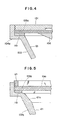
- FIGS. 3 and 4 there is shown a centrifugal separator according to a second preferred embodiment of the present invention.
- a plurality of partitioning members 119 are disposed on an inner wall face 121 of a drum 102 in a similar manner as in the first embodiment described hereinabove.
- a path defining member 120a is adhered to and supported between upper faces of the partitioning members 119 and a distributor 106 and a lower face of a drum cover 101.
- an outer circumferential wall of the path defining member 120a is held in contact with a maximum diameter portion of the inner wall face 121 of the drum 102, and a plurality of concentrated liquid deriving grooves 105a are formed radially in an upper wall of and the outer circumferential wall of the path defining member 120a for establishing communication between deepest portions of collecting chambers 104a and a base end of a concentrated liquid extracting pipe 118.
- the grooves 105a are closed by the inner wall face of the drum 102 and the drum cover 101 to thus form concentrated liquid deriving pipes.
- FIG. 5 illustrates a modification to the concentrated liquid deriving pipes in the embodiment shown in FIGS. 3 and 4.
- a drum cover 101a contacts at an outer circumferential wall thereof with a maximum diameter portion of an inner wall face 121 of a drum 102b and has a plurality of grooves formed in the outer circumferential wall thereof in a communicating relationship with deepest portions of collecting chambers.
- the grooves are communicated with a concentrated liquid extracting pipe by way of a plurality of concentrating liquid deriving holes 105b formed radially in the drum cover 101a.
- a plurality of collecting chambers are defined by the drum cover 101a, a horizontal annular portion of the inner wall face 121 of the drum 102b and a plurality of partitioning members 119.
- Another portion 121a of the inner wall face 121 of the drum 102b adjacent the horizontal annular portion is inclined more gently than a further portion of the inner wall face 121 below the portion 121a.
- the gently inclined portion 121a acts as a particle accelerating section for accelerating therealong particles guided thereto by the further portion therebelow.
- the partitioning members 119 are formed such that the radially inner ends thereof terminate at locations radially outwardly of entrances of the collecting chambers. Further, lower portions of the deepest portions of the collecting chambers are generally rounded so as to eliminate dead spaces.
- FIGS. 6A and 6B there is shown a centrifugal separator according to a third preferred embodiment of the present invention.
- an inclined upper portion of an inner wall face 121 of a drum 102b is formed in a very gently sloped face, and the inner wall face 121 extends vertically upwardly from an outer end of the inclined upper portion thereof and then horizontally radially inwards from an upper end of the vertical portion thereof.
- An annular space extending in a circumferential direction in a rotor 103 is thus defined by the inclined upper portion, vertical portion and horizontal portion of the inner wall face 121 of the drum 102b.
- a single partitioning member 119a is disposed in the annular spacing to form a plurality of collecting chambers, and a plurality of holes are formed in the partitioning member 119a and extend horizontally radially outwards from deepest portions of the collecting chambers to an outer circumferential face of the drum 102b.
- a plurality of concentrated liquid deriving pipes 105c are connected to the radial holes formed in the partitioning member 119a.
- the concentrated liquid deriving pipes 105c extend first horizontally radially outwards, then vertically upwardly and then horizontally radially inwards above a drum cover 101b toward an outer wall (not shown) formed on the drum cover 101b.
- the concentrated liquid deriving pipes 105c are thus connected at the other ends thereof to through-holes (not shown) perforated in the outer wall.
- the centrifugal separator has a substantially similar construction to the centrifugal separator of the first embodiment shown in FIG. 1 except that it includes a plurality of modified concentrated liquid deriving pipes 105d.
- the modified concentrated liquid deriving pipes 105d have a same outer diameter over the entire lengths thereof and contact at the top and bottom portions of the outer circumferential faces thereof respectively with a lower face of a drum cover 101 and a horizontal portion of an inner wall face 121 of a drum 102 which define a plurality of collecting chambers 104 therebetween.
- concentrated liquid of particles flow into each of the collecting chambers 104 through a pair of gaps formed between a concentrated liquid deriving pipe 105d and opposing side faces of a pair of partitioning members 119 located on the opposite sides of the concentrated liquid deriving pipe 105d.
- FIG. 8 illustrates a modification to the centrifugal separator of the fourth embodiment shown in FIG. 7.
- the centrifugal separator shown includes a plurality of modified concentrated liquid deriving pipes 105e to the concentrated liquid deriving pipes 105d of the centrifugal separator shown in FIG. 7.
- the concentrated liquid deriving pipes 105e extend radially outwardly until outer ends thereof contact with an inner wall face 121 of a drum 102 which defines a plurality of collecting chambers 104.
- a plurality of grooves or recesses having a semi-circular cross section corresponding to openings of the concentrated liquid deriving pipes 105d are formed in a vertical maximum diameter portion of the inner wall face 121 of the drum 102.
- concentrated liquid of particles flow into each of the semi-circular recesses of the collecting chambers 104 through a pair of gaps formed between a concentrated liquid deriving pipe 105e and opposing side faces of a pair of partitioning members 119 located on the opposite sides of the concentrated liquid deriving pipe 105d.
Landscapes
- Centrifugal Separators (AREA)
Applications Claiming Priority (2)
| Application Number | Priority Date | Filing Date | Title |
|---|---|---|---|
| JP138447/88 | 1988-06-07 | ||
| JP63138447A JPH07114982B2 (ja) | 1988-06-07 | 1988-06-07 | 遠心分離機 |
Publications (3)
| Publication Number | Publication Date |
|---|---|
| EP0346056A2 true EP0346056A2 (fr) | 1989-12-13 |
| EP0346056A3 EP0346056A3 (en) | 1990-12-05 |
| EP0346056B1 EP0346056B1 (fr) | 1993-12-29 |
Family
ID=15222217
Family Applications (1)
| Application Number | Title | Priority Date | Filing Date |
|---|---|---|---|
| EP89305673A Expired - Lifetime EP0346056B1 (fr) | 1988-06-07 | 1989-06-06 | Séparateur antrifuge |
Country Status (4)
| Country | Link |
|---|---|
| US (1) | US4976678A (fr) |
| EP (1) | EP0346056B1 (fr) |
| JP (1) | JPH07114982B2 (fr) |
| DE (1) | DE68911756T2 (fr) |
Cited By (9)
| Publication number | Priority date | Publication date | Assignee | Title |
|---|---|---|---|---|
| WO2000002663A1 (fr) * | 1998-07-13 | 2000-01-20 | Phase, Inc. | Segregation de particules et procede de transport pour dispositifs de separation de fluides |
| US6706180B2 (en) | 2001-08-13 | 2004-03-16 | Phase Inc. | System for vibration in a centrifuge |
| USRE38494E1 (en) | 1998-07-13 | 2004-04-13 | Phase Inc. | Method of construction for density screening outer transport walls |
| US6755969B2 (en) | 2001-04-25 | 2004-06-29 | Phase Inc. | Centrifuge |
| US6805805B2 (en) | 2001-08-13 | 2004-10-19 | Phase Inc. | System and method for receptacle wall vibration in a centrifuge |
| WO2011120078A1 (fr) | 2010-03-29 | 2011-10-06 | Newcastle Innovation Limited | Dispositif de séparation par gravité améliorée utilisant des canaux étroitement espacés |
| US20220055043A1 (en) * | 2018-12-10 | 2022-02-24 | Alfa Laval Corporate Ab | Exchangeable separation insert |
| US12151250B2 (en) * | 2018-12-10 | 2024-11-26 | Alfa Laval Corporate Ab | Centrifugal separation system and method having control based on pressure |
| US12275021B2 (en) | 2019-01-28 | 2025-04-15 | Alfa Laval Corporate Ab | Centrifugal separator having a screw connection between upper and lower bowls |
Families Citing this family (12)
| Publication number | Priority date | Publication date | Assignee | Title |
|---|---|---|---|---|
| AU704716B2 (en) * | 1994-11-28 | 1999-04-29 | Pulp Tech Pty. Limited | Centrifuge |
| AUPM969894A0 (en) * | 1994-11-28 | 1994-12-22 | Pulp Tech Pty. Limited | Centrifuge |
| EP1610879A4 (fr) | 2003-03-11 | 2007-02-21 | Phase Inc | Centrifugeuse a decharge modulable des materiaux denses |
| US6971525B2 (en) | 2003-06-25 | 2005-12-06 | Phase Inc. | Centrifuge with combinations of multiple features |
| ITMO20030201A1 (it) * | 2003-07-11 | 2005-01-12 | Hs Hospital Service Spa | Sistema di infusione di soluzioni farmacologiche |
| WO2005011848A1 (fr) | 2003-07-30 | 2005-02-10 | Phase Inc. | Systeme de filtration et procede de separation de fluide dynamique |
| EP1663461A4 (fr) | 2003-07-30 | 2009-01-14 | Phase Inc | Systeme de filtration a nettoyage ameliore et separation de fluide dynamique |
| US7282147B2 (en) | 2003-10-07 | 2007-10-16 | Phase Inc. | Cleaning hollow core membrane fibers using vibration |
| DE102005005660A1 (de) * | 2005-02-08 | 2006-08-10 | Westfalia Separator Ag | Separatortrommel |
| JP5966499B2 (ja) * | 2012-03-27 | 2016-08-10 | 三菱化学株式会社 | トナーの製造方法及びトナーの製造装置 |
| JP5936576B2 (ja) * | 2013-03-29 | 2016-06-22 | 富士フイルム株式会社 | 遠心分離用容器および遠心分離装置並びにそれらを用いた遠心分離方法 |
| US20170189915A1 (en) | 2014-05-28 | 2017-07-06 | Gea Mechanical Equipment Gmbh | Separator |
Family Cites Families (18)
| Publication number | Priority date | Publication date | Assignee | Title |
|---|---|---|---|---|
| US1935117A (en) * | 1929-08-29 | 1933-11-14 | Laval Separator Co De | Centrifugal separating bowl |
| US2104683A (en) * | 1933-07-06 | 1938-01-04 | Rosen Van | Dust separator |
| US2259665A (en) * | 1939-02-10 | 1941-10-21 | Sharples Corp | Centrifugal separator |
| US2417747A (en) * | 1943-04-23 | 1947-03-18 | Laval Separator Co De | Centrifuge for separating liquids from gases and heavy impurities |
| FR914249A (fr) * | 1945-04-06 | 1946-10-02 | Procédé d'égoutage du caillé et appareil servant à sa réalisation | |
| BE464440A (fr) * | 1946-02-21 | |||
| US2668008A (en) * | 1950-04-01 | 1954-02-02 | Laval Separator Co De | Centrifugal separator for cold milk products and the like |
| NL128415C (fr) * | 1963-01-26 | |||
| GB1119406A (en) * | 1964-08-19 | 1968-07-10 | Dorr Oliver Inc | Nozzle type centrifugal machines |
| SE402060B (sv) * | 1976-07-29 | 1978-06-19 | Fiber Mech | Fiberforsterkt rotor och sett vid dess tillverkning |
| JPS5927990B2 (ja) * | 1979-08-31 | 1984-07-10 | 哲一 今井 | レコ−ド盤押え具 |
| SE449951B (sv) * | 1983-03-16 | 1987-06-01 | Alfa Laval Ab | Centrifugalseparator med central slamutmatning |
| DE3503581C1 (de) * | 1985-02-02 | 1986-04-17 | Westfalia Separator Ag | Schleudertrommel zum Klaeren und Trennen von Schleuderfluessigkeiten |
| SE450093B (sv) * | 1985-10-30 | 1987-06-09 | Alfa Laval Separation Ab | Inloppsanordning vid centrifugalseparator |
| DE3601814A1 (de) * | 1986-01-22 | 1987-07-23 | Westfalia Separator Ag | Verfahren und vorrichtung zum trennen von zwei fluessigen phasen mittels einer zentrifuge |
| SE452260B (sv) * | 1986-03-12 | 1987-11-23 | Alfa Laval Separation Ab | Centrifugalseparator anordnad for utmatning av en separerad produkt med bestemd koncentration |
| SE502308C2 (sv) * | 1986-04-19 | 1995-10-02 | Westfalia Separator Ag | Kontinuerligt arbetande centrifugtrumma för koncentrering av suspenderade fasta partiklar |
| SE458507B (sv) * | 1987-06-24 | 1989-04-10 | Alfa Laval Marine Power Eng | Foerfarande vid drift av en centrifugalseparator samt centrifugalseparator foer genomfoerande av foerfarandet |
-
1988
- 1988-06-07 JP JP63138447A patent/JPH07114982B2/ja not_active Expired - Lifetime
-
1989
- 1989-05-31 US US07/359,080 patent/US4976678A/en not_active Expired - Fee Related
- 1989-06-06 EP EP89305673A patent/EP0346056B1/fr not_active Expired - Lifetime
- 1989-06-06 DE DE89305673T patent/DE68911756T2/de not_active Expired - Fee Related
Cited By (13)
| Publication number | Priority date | Publication date | Assignee | Title |
|---|---|---|---|---|
| WO2000002663A1 (fr) * | 1998-07-13 | 2000-01-20 | Phase, Inc. | Segregation de particules et procede de transport pour dispositifs de separation de fluides |
| US6312610B1 (en) | 1998-07-13 | 2001-11-06 | Phase Inc. | Density screening outer wall transport method for fluid separation devices |
| USRE38494E1 (en) | 1998-07-13 | 2004-04-13 | Phase Inc. | Method of construction for density screening outer transport walls |
| US6755969B2 (en) | 2001-04-25 | 2004-06-29 | Phase Inc. | Centrifuge |
| US6706180B2 (en) | 2001-08-13 | 2004-03-16 | Phase Inc. | System for vibration in a centrifuge |
| US6805805B2 (en) | 2001-08-13 | 2004-10-19 | Phase Inc. | System and method for receptacle wall vibration in a centrifuge |
| WO2011120078A1 (fr) | 2010-03-29 | 2011-10-06 | Newcastle Innovation Limited | Dispositif de séparation par gravité améliorée utilisant des canaux étroitement espacés |
| EP2552593A4 (fr) * | 2010-03-29 | 2016-02-24 | Newcastle Innovation Ltd | Dispositif de séparation par gravité améliorée utilisant des canaux étroitement espacés |
| US9789490B2 (en) | 2010-03-29 | 2017-10-17 | Newcastle Innovation Limited | Enhanced gravity separation device using closely spaced channels |
| US20220055043A1 (en) * | 2018-12-10 | 2022-02-24 | Alfa Laval Corporate Ab | Exchangeable separation insert |
| US12121912B2 (en) * | 2018-12-10 | 2024-10-22 | Alfa Laval Corporate Ab | Exchangeable separation insert |
| US12151250B2 (en) * | 2018-12-10 | 2024-11-26 | Alfa Laval Corporate Ab | Centrifugal separation system and method having control based on pressure |
| US12275021B2 (en) | 2019-01-28 | 2025-04-15 | Alfa Laval Corporate Ab | Centrifugal separator having a screw connection between upper and lower bowls |
Also Published As
| Publication number | Publication date |
|---|---|
| DE68911756T2 (de) | 1994-04-14 |
| US4976678A (en) | 1990-12-11 |
| JPH07114982B2 (ja) | 1995-12-13 |
| EP0346056B1 (fr) | 1993-12-29 |
| DE68911756D1 (de) | 1994-02-10 |
| JPH01307465A (ja) | 1989-12-12 |
| EP0346056A3 (en) | 1990-12-05 |
Similar Documents
| Publication | Publication Date | Title |
|---|---|---|
| US4976678A (en) | Centrifugal separator | |
| US6183407B1 (en) | Centrifugal separator having axially-extending, angled separation discs | |
| JP2542372B2 (ja) | 遠心分離機 | |
| CN1024905C (zh) | 比液体密度更大的物质从液体中分离出的装置 | |
| JP2801717B2 (ja) | 遠心分離機 | |
| EP1068016B1 (fr) | Rotor de separateur centrifuge | |
| US6467188B1 (en) | Centrifugal pellet dryer apparatus | |
| US5941811A (en) | Centrifugal separator to free a liquid from both lighter particles and heavier particles | |
| KR970004700B1 (ko) | 원심 분리기 | |
| US4326666A (en) | Centrifugal type counterflow contact apparatus | |
| JP2667224B2 (ja) | 遠心分離機 | |
| US5518494A (en) | Centrifugal separator with air entrainment suppression | |
| US5024648A (en) | Centrifugal separator with a discharge device | |
| WO1982002153A1 (fr) | Centrifugeuse auto-purgeante | |
| EP0611322B1 (fr) | Ameliorations relatives a des separateurs | |
| US2209043A (en) | Centrifugal separator bowl | |
| WO1998025705A1 (fr) | Separateur centrifuge avec injection de liquide fluidifiant entre deux creux non fluidises | |
| EP0616557B1 (fr) | Separateur centrifuge | |
| EP0824379A1 (fr) | Separateur centrifuge | |
| US2564899A (en) | Power washing centrifugal separator | |
| US4320006A (en) | Centrifugal oil separator | |
| WO1989008502A1 (fr) | Separateur centrifuge |
Legal Events
| Date | Code | Title | Description |
|---|---|---|---|
| PUAI | Public reference made under article 153(3) epc to a published international application that has entered the european phase |
Free format text: ORIGINAL CODE: 0009012 |
|
| AK | Designated contracting states |
Kind code of ref document: A2 Designated state(s): DE FR GB SE |
|
| PUAL | Search report despatched |
Free format text: ORIGINAL CODE: 0009013 |
|
| AK | Designated contracting states |
Kind code of ref document: A3 Designated state(s): DE FR GB SE |
|
| 17P | Request for examination filed |
Effective date: 19901214 |
|
| RAP1 | Party data changed (applicant data changed or rights of an application transferred) |
Owner name: WESTFALIA SEPARATOR AG |
|
| 17Q | First examination report despatched |
Effective date: 19911030 |
|
| GRAA | (expected) grant |
Free format text: ORIGINAL CODE: 0009210 |
|
| AK | Designated contracting states |
Kind code of ref document: B1 Designated state(s): DE FR GB SE |
|
| ET | Fr: translation filed | ||
| REF | Corresponds to: |
Ref document number: 68911756 Country of ref document: DE Date of ref document: 19940210 |
|
| PLBE | No opposition filed within time limit |
Free format text: ORIGINAL CODE: 0009261 |
|
| STAA | Information on the status of an ep patent application or granted ep patent |
Free format text: STATUS: NO OPPOSITION FILED WITHIN TIME LIMIT |
|
| 26N | No opposition filed | ||
| EAL | Se: european patent in force in sweden |
Ref document number: 89305673.9 |
|
| PGFP | Annual fee paid to national office [announced via postgrant information from national office to epo] |
Ref country code: GB Payment date: 19960528 Year of fee payment: 8 |
|
| PGFP | Annual fee paid to national office [announced via postgrant information from national office to epo] |
Ref country code: FR Payment date: 19960611 Year of fee payment: 8 |
|
| PGFP | Annual fee paid to national office [announced via postgrant information from national office to epo] |
Ref country code: DE Payment date: 19960612 Year of fee payment: 8 |
|
| PGFP | Annual fee paid to national office [announced via postgrant information from national office to epo] |
Ref country code: SE Payment date: 19960619 Year of fee payment: 8 |
|
| PG25 | Lapsed in a contracting state [announced via postgrant information from national office to epo] |
Ref country code: GB Free format text: LAPSE BECAUSE OF NON-PAYMENT OF DUE FEES Effective date: 19970606 |
|
| PG25 | Lapsed in a contracting state [announced via postgrant information from national office to epo] |
Ref country code: SE Effective date: 19970607 |
|
| GBPC | Gb: european patent ceased through non-payment of renewal fee |
Effective date: 19970606 |
|
| PG25 | Lapsed in a contracting state [announced via postgrant information from national office to epo] |
Ref country code: FR Free format text: LAPSE BECAUSE OF NON-PAYMENT OF DUE FEES Effective date: 19980227 |
|
| EUG | Se: european patent has lapsed |
Ref document number: 89305673.9 |
|
| PG25 | Lapsed in a contracting state [announced via postgrant information from national office to epo] |
Ref country code: DE Free format text: LAPSE BECAUSE OF NON-PAYMENT OF DUE FEES Effective date: 19980303 |
|
| REG | Reference to a national code |
Ref country code: FR Ref legal event code: ST |
|
| REG | Reference to a national code |
Ref country code: FR Ref legal event code: ST |