EP0345183A1 - Heuwerbungsmaschine mit einem Rechrad - Google Patents
Heuwerbungsmaschine mit einem Rechrad Download PDFInfo
- Publication number
- EP0345183A1 EP0345183A1 EP89440035A EP89440035A EP0345183A1 EP 0345183 A1 EP0345183 A1 EP 0345183A1 EP 89440035 A EP89440035 A EP 89440035A EP 89440035 A EP89440035 A EP 89440035A EP 0345183 A1 EP0345183 A1 EP 0345183A1
- Authority
- EP
- European Patent Office
- Prior art keywords
- rotor
- axis
- machine according
- articulation
- support
- Prior art date
- Legal status (The legal status is an assumption and is not a legal conclusion. Google has not performed a legal analysis and makes no representation as to the accuracy of the status listed.)
- Granted
Links
Images


Classifications
-
- A—HUMAN NECESSITIES
- A01—AGRICULTURE; FORESTRY; ANIMAL HUSBANDRY; HUNTING; TRAPPING; FISHING
- A01D—HARVESTING; MOWING
- A01D78/00—Haymakers with tines moving with respect to the machine
- A01D78/08—Haymakers with tines moving with respect to the machine with tine-carrying rotary heads or wheels
- A01D78/10—Haymakers with tines moving with respect to the machine with tine-carrying rotary heads or wheels the tines rotating about a substantially vertical axis
- A01D78/1071—Having only one rotor
-
- A—HUMAN NECESSITIES
- A01—AGRICULTURE; FORESTRY; ANIMAL HUSBANDRY; HUNTING; TRAPPING; FISHING
- A01D—HARVESTING; MOWING
- A01D78/00—Haymakers with tines moving with respect to the machine
- A01D78/08—Haymakers with tines moving with respect to the machine with tine-carrying rotary heads or wheels
- A01D78/10—Haymakers with tines moving with respect to the machine with tine-carrying rotary heads or wheels the tines rotating about a substantially vertical axis
- A01D78/12—Haymakers with tines moving with respect to the machine with tine-carrying rotary heads or wheels the tines rotating about a substantially vertical axis the tines having an additional movement superimposed upon their rotary movement
- A01D78/125—Haymakers with tines moving with respect to the machine with tine-carrying rotary heads or wheels the tines rotating about a substantially vertical axis the tines having an additional movement superimposed upon their rotary movement by a guiding track
Definitions
- the present invention relates to a haymaking machine comprising a rotor driven in rotation and provided with working tools for swathing plants on the ground, which rotor is connected to a beam or similar support provided with a device for '' three point coupling for attachment to a drive tractor and, comprises a central support axis carrying a control cam for said tools, this axis being connected to a frame with support rollers which move on the ground in position working and which are arranged such that their axes of rotation lie substantially in two vertical planes which are offset from each other in the direction of movement, the connection between the rotor and the beam comprising an axis substantially horizontal articulation and substantially perpendicular to said beam and which is located between the two above-mentioned vertical planes.
- the rotor of the machine can indeed only move at an angle of small value around the vertical pivot axis if it is to be ensured a correct rotational drive from the tractor. This machine is therefore not capable of ensuring good swathing in all conditions.
- the object of the present invention is in particular to propose a haymaking machine with a swath rotor which can follow the unevenness of the ground and which can adapt to all the curves of the path followed.
- an important characteristic of the invention consists in that the rotor comprises a cover which is articulated on the support beam by means of the substantially horizontal articulation axis and substantially perpendicular to said beam and that the support axis central of the rotor is housed in a bore of the cover so as to be able to rotate during work with respect to said axis of articulation, together with the control cam, the frame with the rollers.
- This arrangement allows the rotor to follow the unevenness of the ground well and to always keep the area for picking up work tools in the most forward part of their trajectory, regardless of the direction of travel. In this case the position of the rotor drive members remains unchanged. The forage is thus correctly collected and swathed in all the curves which the rotor of the machine must follow.
- casters are constantly near the collection area to allow the tools to follow the uneven ground. This is also possible in curves and turns thanks to the possibility that the rotor can pivot around the axis of articulation with the beam in any position.
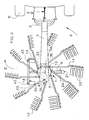
- the machine includes a swath rotor (1).
- This rotor (1) is connected to a beam (2) or to a similar support which extends more or less horizontally.
- This beam (2) is provided with a three-point coupling device (3) for attachment to the lifting rods (4) of a tractor (5).
- said rotor (1) consists of a hub (6) mounted free to rotate on a substantially vertical support axis (7).
- This hub (6) carries a ring gear (8) and a support (9) on which are fixed bearings (10) crossed by arms (11) provided with working tools (12) in the form of forks.
- a second support (13) is provided on the opposite side of the bearings (10) in order to improve their resistance.
- the rotor (1) has ten tool-carrying arms (11). Inside the volume delimited by the two supports (9 and 13), each arm (11) has a lever (14) with a roller (15) which is located in a control cam (16). This is linked to the support axis (7) by means of a key (17).
- This axis (7) is itself carried by a T-shaped frame (18), provided with three support rollers (19, 20, 21) which move on the ground during work.
- These rollers (19, 20, 21) are arranged under the rotor (1) so that their axes of rotation (22) lie substantially in two vertical planes (23 and 24) which are offset relative to the other in the direction of movement indicated by arrow D.
- These two planes (23, 24) are substantially perpendicular to the direction of movement D and are located one at the front and the other at the rear of the support pin (7).
- the three casters (19, 20, 21) are arranged in the shape of a triangle and are located in the vicinity of the path of the working tools (12).
- the support axis (7) also passes through a bore (25) of a cover (26) disposed above the aforementioned hub (6) and the crown (8). At its upper end is provided a stop ring (27) immobilized by means of a pin (28). Said cover (26) has a second bore (29) in which a drive shaft (30) is guided. This has a pinion (31) which meshes with the crown (8) of the hub (6). The other end of this shaft (30) is connected to a transmission shaft (32) which is connected, in a manner known per se, to the PTO shaft of the tractor (5).
- This axis (33) is preferably located between the two vertical planes (23 and 24) containing the axes of rotation (22) of the rollers (19, 20, 21). It can be provided slightly in front of the support axis (7).
- the cover (26) is provided with two ears (34) provided with through holes for the axis (33).
- the beam (2) also includes fixing lugs (35) with through holes for said axis (33). It can be seen in FIG. 1 that the ears (34) are arranged with a slight lateral clearance between two legs (35). The lateral positioning of the rotor (1) relative to the beam (2) is thus obtained in a simple but precise manner.
- the beam (2) is at least partially open downward and covers the upper part of the rotor (1) and the hinge pin (33). It thus ensures effective protection of these parts. It can also be seen in FIG. 1 that the articulation axis (33) is perpendicular to the beam (2) of the machine. The rotor (1) can thus pivot relative to said beam (2) to follow the unevenness of the ground.
- the rotations of the rotor (1) around the articulation axis (33) are limited using a device (36).
- the value of the pivot angle between the two extreme positions of the rotor can be of the order of 12 °. This value is sufficient for the adaptation of the rotor (1) to the unevenness that it can meet on normally maintained ground. This value can however be increased or decreased as appropriate.
- Said device (36) is provided at the rear of the support axis (7). It consists of a tongue (37) secured to the cover (26) of the rotor (1) and two tabs (38) secured to the beam (2).
- the tongue (37) is located between the legs (38) and is connected to the cover (26) of the rotor (1) by means of a yoke (39). It has an oblong hole (40) through which passes an axis (41) housed moreover in circular holes of the two legs (38). Thanks to the oblong hole (40) the tongue (37) can move with the rotor (1) relative to the legs (38). The length of this hole (40) determines the pivot angle of the rotor (1).
- the device (36) also makes it possible to block the rotor (1) relative to the beam (2). Such a blockage is useful in transport, in order to avoid swinging of the rotor (1) around the articulation axis (33) when the machine is carried by the tractor (5).
- the tongue (37) has a cylindrical hole (42) in which the pin (41) can be engaged after having aligned this hole (42) with those provided in the tabs (38).
- the two front castors (19, 20) are pivotable relative to the frame (18) around substantially vertical axes (43), while the rear caster (21) is fixed relative to the frame (18). Due to its offset from the support axis (7), it is constantly positioned behind said axis (7) regardless of the direction of movement of the machine.
- This roulette (21) thus ensures the positioning of the free assembly in rotation constituted by the support axis (7), the control cam (16) and the frame (18) as a function of the direction of movement.
- the machine is moved in direction D (figure 1) and the rotor (1) is rotated from the tractor (5) in the direction of arrow F.
- the rollers (15) of the support arms tools (11) then move in the control cam (16).
- the raceway of said rollers (15) in the cam (16) is such that, on the front part of their trajectory - seen in the direction of movement D - the tools (12) are directed downwards and pick up the lying plants on the ground and that, on the lateral part of their trajectory, they rise and deposit the plants in the form of a swath.
- the support rollers (19, 20, 21) follow the unevenness of the ground and guide the rotor (1). The latter then moves relative to the beam (2) parallel to the direction of movement D around the hinge axis (33) so that its tools (12) constantly touch the ground surface.
- the support axis (7), the control cam (16) and the rollers (19, 20, 21) are automatically oriented so that the area on which the tools (12) pick up the plants lying on the ground is in the most forward part of their trajectory, even in curves and turns.
- the two rollers (19, 20) always remain close to the pickup area. They make the tools (12) follow the unevenness of the ground by rotating the rotor transversely to the direction of movement D since the hinge pin (33) is then more or less directed in this direction D.
Landscapes
- Life Sciences & Earth Sciences (AREA)
- Environmental Sciences (AREA)
- Agricultural Machines (AREA)
- Soil Working Implements (AREA)
- Glass Compositions (AREA)
- Paper (AREA)
- Control Of Multiple Motors (AREA)
- Pharmaceuticals Containing Other Organic And Inorganic Compounds (AREA)
- Harvester Elements (AREA)
- Outside Dividers And Delivering Mechanisms For Harvesters (AREA)
Priority Applications (1)
| Application Number | Priority Date | Filing Date | Title |
|---|---|---|---|
| AT89440035T ATE78970T1 (de) | 1988-06-03 | 1989-04-27 | Heuwerbungsmaschine mit einem rechrad. |
Applications Claiming Priority (2)
| Application Number | Priority Date | Filing Date | Title |
|---|---|---|---|
| FR8807598A FR2632155B1 (fr) | 1988-06-03 | 1988-06-03 | Machine de fenaison comportant un rotor pour andainer |
| FR8807598 | 1988-06-03 |
Publications (2)
| Publication Number | Publication Date |
|---|---|
| EP0345183A1 true EP0345183A1 (de) | 1989-12-06 |
| EP0345183B1 EP0345183B1 (de) | 1992-08-05 |
Family
ID=9367052
Family Applications (1)
| Application Number | Title | Priority Date | Filing Date |
|---|---|---|---|
| EP89440035A Expired - Lifetime EP0345183B1 (de) | 1988-06-03 | 1989-04-27 | Heuwerbungsmaschine mit einem Rechrad |
Country Status (7)
| Country | Link |
|---|---|
| US (1) | US4922700A (de) |
| EP (1) | EP0345183B1 (de) |
| AT (1) | ATE78970T1 (de) |
| DE (1) | DE68902361T2 (de) |
| DK (1) | DK170130B1 (de) |
| ES (1) | ES2034734T3 (de) |
| FR (1) | FR2632155B1 (de) |
Cited By (3)
| Publication number | Priority date | Publication date | Assignee | Title |
|---|---|---|---|---|
| EP0590311A1 (de) * | 1992-09-30 | 1994-04-06 | Claas Saulgau Gmbh | Kreiselkörper für Heumaschinen, insbesondere für Kreiselschwader |
| EP0648407A1 (de) * | 1993-10-18 | 1995-04-19 | GREENLAND GMBH & CO. KG | Heuwerbungsmaschine |
| EP0655188A1 (de) * | 1993-11-25 | 1995-05-31 | Kuhn S.A. | Heuwerbungsmaschine |
Families Citing this family (16)
| Publication number | Priority date | Publication date | Assignee | Title |
|---|---|---|---|---|
| FR2644320B1 (fr) * | 1989-03-20 | 1992-05-07 | Kuhn Sa | Machine agricole avec au moins un rotor pour deplacer des produits se trouvant sur le sol |
| FR2678804B1 (fr) * | 1991-07-11 | 1998-09-18 | Kuhn Sa | Machine de fenaison comportant au moins une roue rateleuse, un dispositif de protection et un deflecteur reglable. |
| FR2718324B1 (fr) * | 1994-04-12 | 1996-06-14 | Kuhn Sa | Machine de fenaison, notamment un andaineur, avec au moins un dispositif d'arrêt du rotor. |
| FR2722365B1 (fr) * | 1994-07-13 | 1996-09-20 | Kuhn Sa Societe Anonyme | Machine de fenaison, notamment une andaineuse de vegetaux a bras porte-fourches commandes |
| FR2740652B1 (fr) * | 1995-11-07 | 1998-01-30 | Kuhn Sa | Machine de fenaison comportant au moins un rotor d'andainage et permettant notamment une meilleure adaptation du rotor au relief du terrain |
| FR2746577B1 (fr) * | 1996-03-29 | 1998-05-29 | Kuhn Sa | Machine de fenaison comportant un dispositif de protection deplacable |
| FR2754136B1 (fr) * | 1996-10-03 | 1999-01-22 | Kuhn Sa | Machine de fenaison comportant un chassis compose de plusieurs troncons articules entre eux |
| FR2756137B1 (fr) * | 1996-11-26 | 1999-01-22 | Kuhn Sa | Machine de fenaison, notamment une andaineuse avec un deflecteur d'andainage reglage automatiquement dans differentes positions |
| US6272826B1 (en) | 1999-04-29 | 2001-08-14 | Sitrex S.R.L. | Method and apparatus for positioning a hay rake |
| FR2806871B1 (fr) * | 2000-04-04 | 2002-12-13 | Kuhn Sa | Machine de fenaison comportant au moins une roue rateleuse articulee sur un bras porteur |
| FR2842067B1 (fr) * | 2002-07-15 | 2005-02-04 | Kuhn Sa | Machine de fenaison avec au moins un rotor perfectionne |
| US7377093B2 (en) * | 2005-10-19 | 2008-05-27 | Cnh America Llc | Rotary crop inverter |
| NL2014732B1 (en) * | 2015-04-29 | 2017-01-18 | Forage Innovations Bv | Agricultural raking device. |
| CN105409455A (zh) * | 2015-12-21 | 2016-03-23 | 中外合资沃得重工(中国)有限公司 | 搂草臂驱动装置 |
| CN105474886A (zh) * | 2016-01-18 | 2016-04-13 | 中外合资沃得重工(中国)有限公司 | 二自由度搂草臂驱动装置 |
| GB201811406D0 (en) * | 2018-07-12 | 2018-08-29 | Agco Feucht Gmbh | Towed agricultural implement |
Citations (10)
| Publication number | Priority date | Publication date | Assignee | Title |
|---|---|---|---|---|
| FR1374202A (fr) * | 1962-11-24 | 1964-10-02 | Fella Werke Gmbh | Faneuse |
| FR1566084A (de) * | 1967-06-01 | 1969-05-02 | ||
| DE2059269A1 (de) * | 1969-12-04 | 1971-06-09 | Poettinger Ohg Alois | Kreiselrechen |
| FR2093488A5 (de) * | 1970-05-13 | 1972-01-28 | Bautz Gmbh Josef | |
| FR2127029A1 (de) * | 1970-12-11 | 1972-10-13 | Lely Nv C Van Der | |
| FR2358820A1 (fr) * | 1976-07-22 | 1978-02-17 | Kuhn Sa | Machine agricole pour la fenaison |
| FR2415955A1 (fr) * | 1978-02-06 | 1979-08-31 | Kuhn Sa | Machine de fenaison permettant d'andainer en marche avant et en marche arriere |
| DE2833814A1 (de) * | 1978-08-02 | 1980-02-21 | Stoll Maschf Gmbh Wilhelm | Heuwerbungsmaschine |
| DE3628604A1 (de) * | 1986-08-22 | 1988-02-25 | Fella Werke Gmbh | Heuwerbungsmaschine |
| EP0318407A1 (de) * | 1987-11-17 | 1989-05-31 | Kuhn S.A. | Heuerntemaschine mit mindestens einem Rechrad mit gesteuerten Werkzeug-Tragarmen |
Family Cites Families (4)
| Publication number | Priority date | Publication date | Assignee | Title |
|---|---|---|---|---|
| CH459641A (de) * | 1967-11-09 | 1968-07-15 | Bucher Guyer Ag Masch | Selbstfahrende Heuerntemaschine |
| AT314248B (de) * | 1971-04-21 | 1974-03-25 | Poettinger Ohg Alois | Lagerung der ungelenkten Nachlaufräder von landwirtschaftlichen Geräten |
| SE449417B (sv) * | 1979-05-02 | 1987-05-04 | Bucher Guyer Ag Masch | Hoberedningsmaskin samt sett att astadkomma olika onskade rorelser hos refspinnarna vid en hoberedningsmaskin |
| DE8624359U1 (de) * | 1986-09-11 | 1986-10-16 | Fella-Werke Gmbh, 8501 Feucht | Heuwerbungsmaschine |
-
1988
- 1988-06-03 FR FR8807598A patent/FR2632155B1/fr not_active Expired - Fee Related
-
1989
- 1989-04-27 ES ES198989440035T patent/ES2034734T3/es not_active Expired - Lifetime
- 1989-04-27 DE DE8989440035T patent/DE68902361T2/de not_active Expired - Fee Related
- 1989-04-27 EP EP89440035A patent/EP0345183B1/de not_active Expired - Lifetime
- 1989-04-27 AT AT89440035T patent/ATE78970T1/de not_active IP Right Cessation
- 1989-05-26 US US07/357,278 patent/US4922700A/en not_active Expired - Lifetime
- 1989-06-02 DK DK269489A patent/DK170130B1/da not_active IP Right Cessation
Patent Citations (10)
| Publication number | Priority date | Publication date | Assignee | Title |
|---|---|---|---|---|
| FR1374202A (fr) * | 1962-11-24 | 1964-10-02 | Fella Werke Gmbh | Faneuse |
| FR1566084A (de) * | 1967-06-01 | 1969-05-02 | ||
| DE2059269A1 (de) * | 1969-12-04 | 1971-06-09 | Poettinger Ohg Alois | Kreiselrechen |
| FR2093488A5 (de) * | 1970-05-13 | 1972-01-28 | Bautz Gmbh Josef | |
| FR2127029A1 (de) * | 1970-12-11 | 1972-10-13 | Lely Nv C Van Der | |
| FR2358820A1 (fr) * | 1976-07-22 | 1978-02-17 | Kuhn Sa | Machine agricole pour la fenaison |
| FR2415955A1 (fr) * | 1978-02-06 | 1979-08-31 | Kuhn Sa | Machine de fenaison permettant d'andainer en marche avant et en marche arriere |
| DE2833814A1 (de) * | 1978-08-02 | 1980-02-21 | Stoll Maschf Gmbh Wilhelm | Heuwerbungsmaschine |
| DE3628604A1 (de) * | 1986-08-22 | 1988-02-25 | Fella Werke Gmbh | Heuwerbungsmaschine |
| EP0318407A1 (de) * | 1987-11-17 | 1989-05-31 | Kuhn S.A. | Heuerntemaschine mit mindestens einem Rechrad mit gesteuerten Werkzeug-Tragarmen |
Cited By (4)
| Publication number | Priority date | Publication date | Assignee | Title |
|---|---|---|---|---|
| EP0590311A1 (de) * | 1992-09-30 | 1994-04-06 | Claas Saulgau Gmbh | Kreiselkörper für Heumaschinen, insbesondere für Kreiselschwader |
| EP0648407A1 (de) * | 1993-10-18 | 1995-04-19 | GREENLAND GMBH & CO. KG | Heuwerbungsmaschine |
| EP0655188A1 (de) * | 1993-11-25 | 1995-05-31 | Kuhn S.A. | Heuwerbungsmaschine |
| FR2712768A1 (fr) * | 1993-11-25 | 1995-06-02 | Kuhn Sa | Machine de fenaison pour l'andainage de fourrage, avec au moins un rotor entraîné en rotation. |
Also Published As
| Publication number | Publication date |
|---|---|
| ATE78970T1 (de) | 1992-08-15 |
| FR2632155B1 (fr) | 1991-10-11 |
| DE68902361T2 (de) | 1993-05-13 |
| FR2632155A1 (fr) | 1989-12-08 |
| DK170130B1 (da) | 1995-06-06 |
| US4922700A (en) | 1990-05-08 |
| DK269489A (da) | 1989-12-04 |
| DK269489D0 (da) | 1989-06-02 |
| DE68902361D1 (de) | 1992-09-10 |
| EP0345183B1 (de) | 1992-08-05 |
| ES2034734T3 (es) | 1993-04-01 |
Similar Documents
| Publication | Publication Date | Title |
|---|---|---|
| EP0345183B1 (de) | Heuwerbungsmaschine mit einem Rechrad | |
| CA1062920A (fr) | Machine de fenaison pour le fanage et l'andainage | |
| EP0337909B1 (de) | Direktangetriebene Mähmaschine | |
| EP0318407B1 (de) | Heuerntemaschine mit mindestens einem Rechrad mit gesteuerten Werkzeug-Tragarmen | |
| EP0403409B1 (de) | Landmaschine zum Schwaden mit zusammenklappbaren Werkzeugträgern | |
| EP0390713B1 (de) | Landmaschine mit mindestens einem Rechrad zum Versetzen von sich auf dem Boden befindlichen Produkten | |
| EP0772969B1 (de) | Heuwerbungsmaschine mit mindestens einem Rotor zum Schwaden | |
| EP1142468A1 (de) | Heuwerbungsmaschine | |
| EP0614604B1 (de) | Heuwerbungsmaschine | |
| EP0514302B1 (de) | Verbesserter Pflanzenschwader | |
| FR2560737A1 (fr) | Faneuse andaineuse | |
| EP0680688B1 (de) | Heuwerbungsmaschine, insbesondere ein Schwader für Futter | |
| EP0954956B1 (de) | Heuwerbungsmaschine | |
| EP0536071B1 (de) | Heuwerbungsmaschine, insb. ein Zetter für Pflanzengut, mit zumindest zwei Arbeitsstellungen | |
| EP0554200B1 (de) | Heuwerbungsmaschine mit einem mit gesteuerten Stützrädern versehenen Rahmen | |
| FR2707450A1 (fr) | Machine de fenaison avec des rotors de fanage ou d'andainage munis de roues d'appui au sol. | |
| EP0654209B1 (de) | Heuwerbungsmaschine | |
| EP1523232B1 (de) | Heumaschine | |
| FR2719742A1 (fr) | Machine de fenaison, notamment une faneuse à rotors munis de bras porte-fourches avec des déflecteurs. | |
| EP0198781A1 (de) | Heuerntemaschine zum Vorwärts- und Rückwärtsschwaden | |
| EP0442833B1 (de) | Heuwerbungsmaschine mit verbesserter Schutzvorrichtung | |
| EP0914766A1 (de) | Heuwerbungsmachine | |
| FR2646315A1 (fr) | Machine agricole comportant au moins un rotor muni d'outils et s'appuyant sur le sol durant le travail | |
| FR2623050A1 (fr) | Machine de fenaison avec au moins une roue rateleuse equipee de bras porte-outils commandes | |
| FR2553253A1 (fr) | Dispositif andaineur place a l'arriere d'une faucheuse |
Legal Events
| Date | Code | Title | Description |
|---|---|---|---|
| PUAI | Public reference made under article 153(3) epc to a published international application that has entered the european phase |
Free format text: ORIGINAL CODE: 0009012 |
|
| AK | Designated contracting states |
Kind code of ref document: A1 Designated state(s): AT DE ES FR IT NL |
|
| 17P | Request for examination filed |
Effective date: 19900418 |
|
| 17Q | First examination report despatched |
Effective date: 19910612 |
|
| GRAA | (expected) grant |
Free format text: ORIGINAL CODE: 0009210 |
|
| ITF | It: translation for a ep patent filed |
Owner name: BARZANO' E ZANARDO MILANO S.P.A. |
|
| AK | Designated contracting states |
Kind code of ref document: B1 Designated state(s): AT DE ES FR IT NL |
|
| REF | Corresponds to: |
Ref document number: 78970 Country of ref document: AT Date of ref document: 19920815 Kind code of ref document: T |
|
| REF | Corresponds to: |
Ref document number: 68902361 Country of ref document: DE Date of ref document: 19920910 |
|
| REG | Reference to a national code |
Ref country code: ES Ref legal event code: FG2A Ref document number: 2034734 Country of ref document: ES Kind code of ref document: T3 |
|
| PLBE | No opposition filed within time limit |
Free format text: ORIGINAL CODE: 0009261 |
|
| STAA | Information on the status of an ep patent application or granted ep patent |
Free format text: STATUS: NO OPPOSITION FILED WITHIN TIME LIMIT |
|
| 26N | No opposition filed | ||
| PGFP | Annual fee paid to national office [announced via postgrant information from national office to epo] |
Ref country code: NL Payment date: 20030324 Year of fee payment: 15 Ref country code: AT Payment date: 20030324 Year of fee payment: 15 |
|
| PGFP | Annual fee paid to national office [announced via postgrant information from national office to epo] |
Ref country code: DE Payment date: 20030409 Year of fee payment: 15 |
|
| PGFP | Annual fee paid to national office [announced via postgrant information from national office to epo] |
Ref country code: ES Payment date: 20030411 Year of fee payment: 15 |
|
| PGFP | Annual fee paid to national office [announced via postgrant information from national office to epo] |
Ref country code: FR Payment date: 20030425 Year of fee payment: 15 |
|
| PG25 | Lapsed in a contracting state [announced via postgrant information from national office to epo] |
Ref country code: AT Free format text: LAPSE BECAUSE OF NON-PAYMENT OF DUE FEES Effective date: 20040427 |
|
| PG25 | Lapsed in a contracting state [announced via postgrant information from national office to epo] |
Ref country code: ES Free format text: LAPSE BECAUSE OF NON-PAYMENT OF DUE FEES Effective date: 20040428 |
|
| PG25 | Lapsed in a contracting state [announced via postgrant information from national office to epo] |
Ref country code: NL Free format text: LAPSE BECAUSE OF NON-PAYMENT OF DUE FEES Effective date: 20041101 |
|
| PG25 | Lapsed in a contracting state [announced via postgrant information from national office to epo] |
Ref country code: DE Free format text: LAPSE BECAUSE OF NON-PAYMENT OF DUE FEES Effective date: 20041103 |
|
| PG25 | Lapsed in a contracting state [announced via postgrant information from national office to epo] |
Ref country code: FR Free format text: LAPSE BECAUSE OF NON-PAYMENT OF DUE FEES Effective date: 20041231 |
|
| NLV4 | Nl: lapsed or anulled due to non-payment of the annual fee |
Effective date: 20041101 |
|
| REG | Reference to a national code |
Ref country code: FR Ref legal event code: ST |
|
| PG25 | Lapsed in a contracting state [announced via postgrant information from national office to epo] |
Ref country code: IT Free format text: LAPSE BECAUSE OF NON-PAYMENT OF DUE FEES Effective date: 20050427 |
|
| REG | Reference to a national code |
Ref country code: ES Ref legal event code: FD2A Effective date: 20040428 |