EP0345077B1 - Verkleidungssystem - Google Patents
Verkleidungssystem Download PDFInfo
- Publication number
- EP0345077B1 EP0345077B1 EP89305578A EP89305578A EP0345077B1 EP 0345077 B1 EP0345077 B1 EP 0345077B1 EP 89305578 A EP89305578 A EP 89305578A EP 89305578 A EP89305578 A EP 89305578A EP 0345077 B1 EP0345077 B1 EP 0345077B1
- Authority
- EP
- European Patent Office
- Prior art keywords
- facing
- panels
- earth
- panel
- sloping
- Prior art date
- Legal status (The legal status is an assumption and is not a legal conclusion. Google has not performed a legal analysis and makes no representation as to the accuracy of the status listed.)
- Expired - Lifetime
Links
- 230000003019 stabilising effect Effects 0.000 claims abstract description 16
- 239000004567 concrete Substances 0.000 description 9
- 230000001965 increasing effect Effects 0.000 description 7
- 239000000463 material Substances 0.000 description 6
- 238000000034 method Methods 0.000 description 5
- 239000002689 soil Substances 0.000 description 4
- 229910000831 Steel Inorganic materials 0.000 description 3
- 230000003628 erosive effect Effects 0.000 description 3
- 239000002245 particle Substances 0.000 description 3
- 239000011150 reinforced concrete Substances 0.000 description 3
- 239000010959 steel Substances 0.000 description 3
- 238000010276 construction Methods 0.000 description 2
- 230000000694 effects Effects 0.000 description 2
- 239000004746 geotextile Substances 0.000 description 2
- 230000008635 plant growth Effects 0.000 description 2
- 125000006850 spacer group Chemical group 0.000 description 2
- 238000005452 bending Methods 0.000 description 1
- 230000015572 biosynthetic process Effects 0.000 description 1
- 238000004891 communication Methods 0.000 description 1
- 239000007799 cork Substances 0.000 description 1
- 238000005260 corrosion Methods 0.000 description 1
- 230000007797 corrosion Effects 0.000 description 1
- 238000006073 displacement reaction Methods 0.000 description 1
- 230000005489 elastic deformation Effects 0.000 description 1
- 230000002708 enhancing effect Effects 0.000 description 1
- 230000005484 gravity Effects 0.000 description 1
- 230000002262 irrigation Effects 0.000 description 1
- 238000003973 irrigation Methods 0.000 description 1
- 238000004519 manufacturing process Methods 0.000 description 1
- 239000002184 metal Substances 0.000 description 1
- 238000000465 moulding Methods 0.000 description 1
- 239000011347 resin Substances 0.000 description 1
- 229920005989 resin Polymers 0.000 description 1
- 238000004901 spalling Methods 0.000 description 1
- 230000006641 stabilisation Effects 0.000 description 1
- 239000010935 stainless steel Substances 0.000 description 1
Images


Classifications
-
- E—FIXED CONSTRUCTIONS
- E02—HYDRAULIC ENGINEERING; FOUNDATIONS; SOIL SHIFTING
- E02D—FOUNDATIONS; EXCAVATIONS; EMBANKMENTS; UNDERGROUND OR UNDERWATER STRUCTURES
- E02D29/00—Independent underground or underwater structures; Retaining walls
- E02D29/02—Retaining or protecting walls
- E02D29/0258—Retaining or protecting walls characterised by constructional features
- E02D29/0266—Retaining or protecting walls characterised by constructional features made up of preformed elements
-
- E—FIXED CONSTRUCTIONS
- E02—HYDRAULIC ENGINEERING; FOUNDATIONS; SOIL SHIFTING
- E02D—FOUNDATIONS; EXCAVATIONS; EMBANKMENTS; UNDERGROUND OR UNDERWATER STRUCTURES
- E02D29/00—Independent underground or underwater structures; Retaining walls
- E02D29/02—Retaining or protecting walls
- E02D29/0225—Retaining or protecting walls comprising retention means in the backfill
- E02D29/0241—Retaining or protecting walls comprising retention means in the backfill the retention means being reinforced earth elements
-
- E—FIXED CONSTRUCTIONS
- E02—HYDRAULIC ENGINEERING; FOUNDATIONS; SOIL SHIFTING
- E02D—FOUNDATIONS; EXCAVATIONS; EMBANKMENTS; UNDERGROUND OR UNDERWATER STRUCTURES
- E02D29/00—Independent underground or underwater structures; Retaining walls
- E02D29/02—Retaining or protecting walls
- E02D29/025—Retaining or protecting walls made up of similar modular elements stacked without mortar
Definitions
- the present invention relates to a facing system for a frictionally stabilised earth structure.
- United States Patent No. 3421326 of Henri Vidal describes earth structures including retaining walls wherein stability is achieved by compacting successive layers of earth into frictional contact with stabilising members. In this way, the frictional forces between the stabilising members and the adjacent earth particles, and between the earth particles themselves, resist failure caused by lateral earth movement and the resulting tensile forces in the stabilising members, which inevitably have some measure of elasticity, permit slight elastic deformation of the stabilised earth mass thereby enhancing its stability.
- This technique enables retaining walls for embankments and the like to have at least one substantially vertical face and such a face will normally be clad with a facing system which, in order to conform to small movements created by the above compacting procedure and to accommodate the small elastic or even permanent movements of the structure permitted by the stabilisation technique, are preferably flexible in the plane of the face. In general, such flexibility can be provided by facing panels attached to the stabilising members which are arranged accurately to terminate at the vertical face concerned.
- Such panel facing systems provide a high level of architectural finish and satisfactorily resist erosion of the earth of the retaining wall.
- retaining wall systems for architectural effects involving growing plants which not only provide an attractive, softer surface appearance but may also serve to absorb sound in urban traffic environments and at airports.
- Such systems contrive to provide areas of exposed earth in an otherwise fully clad facing, commonly by incorporating box-like sections into the wall or by constructing a caisson-type gravity wall with exposed earth areas.
- Such walls tend to use significantly more reinforced concrete or similar materials than a conventional flat facing, particularly the relatively thin facing systems used in the frictional stabilising technique described above.
- Japanese Patent Application 59-169733 describes a facing system for reinforced earth structures built up from units comprising two side walls and a flat or curved facing panel which slopes rearward from top to bottom. These units are stacked to form a facing in which the units are juxtaposed in both lateral and vertical contact whereby each unit exposes, for planting, a substantially flat bed of earth immediately beneath each facing panel.
- a facing system for a frictionally stabilised earth structure comprising an assembly of sloping facing panels each of which has a substantially horizontal upper edge and a lower edge situated rearward of said upper edge and substantially parallel thereto, support means being provided to support said facing panels to form a series of superimposed substantially horizontal tiers, said panels and/or said support means being provided with means for attachment to frictional stabilising members embedded in the earth of said structure, characterised in that the sloping facing panels in said tiers are laterally spaced and are positioned vertically above corresponding lateral spaces between facing panels in the tier below, whereby earth immediately behind said structure in contact with said facing panels, forms an open sloping surface from the lower edge of each facing panel through the space in the tier immediately below to the upper edge of the facing panel vertically below said space, the slope of said surface being less than the angle of repose of the earth, earth retaining means, which optionally function as the said support means, being provided on each side of each said facing panel to restrain lateral
- the support means for the sloping facing panels are conveniently side panels lying perpendicular to the plane of the facing which will be in contact with all or part of side edges of the facing panels.
- Such side panels will normally also serve as the earth retaining means preventing lateral movement of the earth.
- each unit comprising a facing panel secured perpendicularly to two side panels the shorter edges of said facing panel being in contact with said side panels at an angle to the upper and lower edges of said side panels, the facing panel of each unit sloping with its upper edge forward of its lower edge, said units being assembled in a series of superimposed horizontal tiers, characterised in that each unit in said tiers is spaced from the two laterally adjacent units and the side panels of the units of each tier are supported by the upper surfaces of the side panels of the units of the tier below, sloping facing panels in a superimposed tier lying vertically above spaces between laterally adjacent sloping facing panels of the tier below.
- a frictionally stabilised earth structure comprising a facing system as described above, the facing system being attached to frictional stabilising members embedded in the earth of said structure.
- the sloping facing panels and side panels of the above system will normally be made of reinforced concrete.
- the side panels and the sloping facing panels of the above units will normally be substantially flat slabs and in a preferred embodiment of the invention they may be provided separately and assembled into the units, conveniently at the construction site.
- Such flat elements lend themselves to transport in that they may be readily stacked, in contrast with completed units of more complex shape and are particularly simple to produce in large numbers by moulding.
- the side panels may thus be provided with appropriate holes and the facing panels may have appropriately positioned threaded holes, for example provided by coil inserts. It is also possible to provide the facing panels with integral bolts, the inner ends of which are embedded in the material of the panel and which extend sufficiently far to pass through holes in the side panels whereby securing nuts may be attached.
- a single bolt on each end of the facing panel is normally sufficient to secure the assembled unit, particularly where the panels additionally cooperate with the side panels to restrict movement, but two such bolts may be provided. It is preferred to provide each side panel with a groove which receives and partly secures one side edge of the respective facing panel at the designed slope.
- Such a groove may be about 4cm in depth and can usefully be substantially oversized in relation to the dimensions of the cooperating end of the facing panel to simplify assembly.
- Such a groove may advantageously be wider at the top than the bottom, again to facilitate assembly, the positioning of bolts and holes in the panels determining the precise slope of the facing panel.
- the means for attachment of the units to stabilising members embedded in the earth may conveniently be lugs or other metal plates extending rearwards from each of the side panels, such lugs or plates having holes to take securing bolts.
- the most preferred stabilising members are strips, normally of corrosion resistant steel, e.g. galvanised steel, provided with a hole at the end terminating at the facing adapted to receive the securing bolts referred to above. Such strips are described in our United Kingdom Patent No. 1563317.
- the stabilising strips are thickened at the region of the said hole to resist tensile forces and possible corrosion;
- the lugs or plates on the side panels of the facing units are advantageously in closely spaced pairs such that the end of the stabilising strip can be inserted therebetween to receive a bolt passing through the three aligned holes.
- Such paired lugs or plates can conveniently be provided by a U-shaped strip of galvanised steel embedded in the side panels, advantageously being so bent that the base of the U- section is expanded to resist pulling out of the member from the concrete of the panel.
- the units may be stacked to provide a substantially vertical facing or may be slightly displaced to provide an angled or battered facing. Since the units are normally individually secured to stabilising members, it is not necessary to secure the units together and they will, in general, simply be stacked in the formation stated above, which may be likened to the arrangement of the black squares of a chessboard. Normally semi-flexible rubber (or resin bonded cork) pads will be placed between the superimposed side panels.
- earth slopes provided by the alternate spaces between the units are adapted to receive plants. Since the bottom of the facing panel of the unit above such a space is substantially rearward of the top of the facing panel of the unit immediately below, as indicated above, the exposed earth in the space will be at an angle to the horizontal which in order to avoid loss of earth from such a slope, should not be significantly greater than the angle of repose of the earth, even though plant growth will eventually partially stabilise the slope.
- This angle may in general vary between tan ⁇ 1 0.4 and tan ⁇ 1 0.8 to the horizontal, and is preferably about tan ⁇ 1 0.67. This consideration is an important factor in determining the dimensions of the facing units and the slopes of the front panels, which may for example be arranged substantially perpendicularly to the earth slopes as mentioned hereinafter.
- each facing panel engages with the side panels approximately along a diagonal of the latter.
- the angle of the facing panels to the horizontal is advantageously about tan ⁇ 1 0.6.
- Such arrangements can ensure that the slope of the exposed earth does not exceed the angle of repose while substantially keeping the amount of concrete in the facing to a minimum. If the angle of such flat facing panels is substantially less than about tan ⁇ 1 0.6, it will be appreciated that the length of the diagonal of each side panel will have to be greater, so that not only will the top to bottom dimension of the front panels be greater but the side panels will also be longer from front to back, thereby using more concrete.
- Such arrangements have the advantage of providing larger planting areas, although in view of the smaller slope of the facing panels the rear parts of such planting areas tend to be undesirably sheltered from rain.
- the upper edges of the facing panels may project above the upper edges of the side panels, thus making the vertical elevation of each facing panel greater than that of each of the exposed earth sections.
- This permits the earth in the exposed sections to be raised at the rear to a level above the bottom edge of the vertically adjacent facing panel without exceeding the angle of repose, thus providing a margin for security against erosion of soil in the region of that lower edge where soil from above might otherwise 'flow' under the panel.
- the lower edges of the facing panels may project below the lower edges of the side panels to produce essentially the same effect.
- the sections of the facing panel which project upwards or downwards in this way will normally not engage with the side panels of the vertically adjacent units and where the panel is inset into a groove into the side panels to which it is bolted, the projecting section can be made narrower than the inset part to avoid such engagement.
- an insert of geotextile or similar material may be introduced.
- the gap may be as large as 4 or 5cm (particularly when the facing is curved as discussed later) so that the insert may sometimes be a small block of concrete.
- the tops of the facing panels in any tier of facing units can be rearward of the tops of the facing panels immediately below.
- the height of the panels i.e. their vertical elevation
- the corresponding increase in the vertical distance between the bottom of an upper panel and the top of that below is compensated by the increased horizontal spacing thus maintaining the angle of the earth slope.
- the angle of the facing panels to the horizontal may be increased, while maintaining their vertical elevation, thus compensating for the increase in rearward horizontal spacing and again maintaining the angle of the earth slope.
- the facing panels to project beyond the side panels thus increasing their vertical elevation permits the angle of the facing panels to the horizontal to be increased while permitting the slope of the exposed earth to remain not greater than the angle of repose.
- This enables the facing panels to be substantially perpendicular to the sloping earth surfaces, thereby increasing the depth of soil near the front of the panel and the ability to collect rainwater for irrigation, both factors assisting the growth of plants on the exposed earth areas.
- the angle of the facing panels to the horizontal may be between tan ⁇ 1 0.4 and tan ⁇ 1 2.5 , preferably between tan ⁇ 1 0.45 and tan ⁇ 1 1.5.
- the front edges of the side panels may slope backwards at the same angle as the overall slope of the facing, thereby aligning them in the vertical direction.
- the facing panels may typically have a lateral extent or width of 2.0m, a height of 0.8m and a thickness of 0.1m.
- a lateral extent or width of 2.0m By increasing the width of the facing panels fewer support means at the panel side edges are required for a given width of structure, and thus there may be savings in the material such as concrete which is used.
- the width of the facing panels is limited by the requirement to avoid an excessive mid-span bending moment and ease of transportation.
- the simple stacking procedure used to assemble the facing system of the invention permits the facing to be curved.
- the side panels of units in a superimposed tier may be angled slightly with respect to the side panels of a lower tier on which they rest, provided a sufficient area of contact exists for the side panels to maintain their supporting function.
- One way of building a curved facing is to vary the angle of the facing panels with respect to the supporting side panels by using two bolts to form each facing panel-to-side panel connection, with washers of suitable thickness located on the bolts to achieve the desired angle. To achieve sharper curvatures it may be desirable to use shorter lengths of facing panels.
- a reinforced concrete facing unit 1 comprises a pair of laterally spaced side panels 2 which support a facing panel 3.
- the side panels are rectangular in shape and are each provided with a recessed groove 4 extending between diagonally opposite corners for receiving the ends of the facing panel 3 which is also of rectangular shape.
- the grooves 4 are of tapered configuration, being widest at the upper, front corner of the side panel, so as to assist location of the facing panel in the supporting grooves.
- the side panels 2 are formed with a hole 5 for receiving a bolt which engages in a coil insert (not shown) located at the ends of the associated facing panel.
- the side panels 2 are also provided with a pair of circular openings 6 disposed on opposite sides of the groove for the purpose of reducing the amount of concrete used to form the panels.
- a U-shaped strip 7 of galvanised steel is embedded in the rear of the side panels to provide a pair of rearwardly projecting lugs 8 to which stabilising members may be attached.
- Fig. 3 shows three facing units 1a, 1b and 1c stacked on top of each other to form a facing system at the front of a body of earth backfill 9.
- the lower and upper facing units 1a and 1c each have a facing panel 3a and 3c with an exposed earth slope 10 extending between the top of the lower facing panel 3a and the bottom of the upper facing panel 3c.
- the side panel 2b of the middle facing unit 1b supports a facing panel 3b on its remote side.
- Each facing unit is located slightly rearwardly of the one below so that the front of the facing overall slopes to the rear at an angle of tan ⁇ 10.1 to the vertical.
- the rear openings 6 formed in the side panels are located such that earth is disposed on each side thereof, whilst the front openings 6 are open to air on each side thereof.
- the openings 6 communicate either earth to earth or air to air and thus avoid an earth to air communication which would permit earth to spill from the opening.
- the illustrated openings are circular, any convenient shape may be selected.
- the facing panels shown in Figs. 1 to 3 may typically have a lateral extent (width) of 2.0m, a height of 0.8m and a thickness of 0.1m.
- the side panels may have a length (front to rear) of 0.85m, a height of 0.5m and a thickness of 0.1m.
- the facing panels are arranged along the diagonal of the side panels and thus slope at an angle to the horizontal of tan ⁇ 1 (0.5/0.85), i.e. tan ⁇ 10.59.
- the earth slope 10 is at a slightly greater angle to the horizontal although not greater than tan ⁇ 1 0.67.
- the facing panels 3 supported in the side panel grooves 4 project upwardly above the upper surface of the side panels.
- the upwardly projecting portion 11 of each facing panel is of reduced width so as to avoid snarling on the side panels of the tier above.
- the resulting spaces are covered by geotextile inserts 12 to prevent escape of earth.
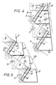
- the facing systems of Figs. 4 to 8 include resilient e.g. rubber spacer members 13 located between the stacked side panels. These spacer members enable limited vertical movement of the facing to accommodate any settlement of the earth backfill and avoid any spalling of concrete.
- the exposed earth slope 10 is at an angle of tan ⁇ 10.67 to the horizontal, whilst the facing panels are arranged perpendicularly to the earth slope, i.e. at an angle of tan ⁇ 11.5 to the horizontal.
- Each side panel is located slightly to the rear of the side panel below such that the overall slope 20 of the facing is tan ⁇ 1 0.1 to the vertical, and the front surface 14 of each side panel also slopes rearwardly at an angle of tan ⁇ 1 0.1 to the vertical, so that the front surfaces 14 are aligned with each other.
- the exposed earth slope 10 is also at an angle of tan ⁇ 10.67 to the horizontal, the facing panels being again perpendicular to the earth slope.
- This embodiment differs from that of Fig. 4 in that the side panels are stacked such that the overall slope 20 of the facing is tan ⁇ 1 0.5 to the vertical i.e. the facing slopes backwards to a greater extent. This means that the exposed earth slopes 10 are of greater length than the height of the facing panels, providing an increased planting area.
- each facing panel projects upwards to a greater extent than in the embodiments of Figs 4 and 5, such that the level of the exposed earth slopes 10 are raised, having an extra portion 15.
- the earth slope is again at an angle of tan ⁇ 10.67 to the horizontal, whilst in this instance the facing panels are not perpendicular to the earth slope, but rather are at an angle of tan ⁇ 11.0 to the horizontal.
- the overall slope 20 of the facing is tan ⁇ 1 0.1 to the vertical.
- Figs. 7 and 8 The embodiment of Figs. 7 and 8 is similar to that of Fig. 6 in that an extra earth portion 13 is provided.
- the earth slope 10 is at a less steep angle i.e. an angle of tan ⁇ 1 0.57 to the horizontal.
- the facing panels are at an angle tan ⁇ 11.0 to the horizontal, whilst the overall slope 20 of the facing is tan ⁇ 10.25 to the vertical.
Landscapes
- Engineering & Computer Science (AREA)
- Environmental & Geological Engineering (AREA)
- Life Sciences & Earth Sciences (AREA)
- General Life Sciences & Earth Sciences (AREA)
- Mining & Mineral Resources (AREA)
- Paleontology (AREA)
- Civil Engineering (AREA)
- General Engineering & Computer Science (AREA)
- Structural Engineering (AREA)
- Pit Excavations, Shoring, Fill Or Stabilisation Of Slopes (AREA)
- Auxiliary Methods And Devices For Loading And Unloading (AREA)
- Valve Device For Special Equipments (AREA)
- Grinding Of Cylindrical And Plane Surfaces (AREA)
- Glass Compositions (AREA)
- Transplanting Machines (AREA)
- Laminated Bodies (AREA)
- Superconductors And Manufacturing Methods Therefor (AREA)
- Manufacture Of Alloys Or Alloy Compounds (AREA)
- Coating Apparatus (AREA)
- Retaining Walls (AREA)
Claims (10)
Priority Applications (1)
| Application Number | Priority Date | Filing Date | Title |
|---|---|---|---|
| AT89305578T ATE76140T1 (de) | 1988-06-03 | 1989-06-02 | Verkleidungssystem. |
Applications Claiming Priority (2)
| Application Number | Priority Date | Filing Date | Title |
|---|---|---|---|
| GB888813146A GB8813146D0 (en) | 1988-06-03 | 1988-06-03 | Facing system |
| GB8813146 | 1988-06-03 |
Publications (3)
| Publication Number | Publication Date |
|---|---|
| EP0345077A2 EP0345077A2 (de) | 1989-12-06 |
| EP0345077A3 EP0345077A3 (en) | 1990-02-07 |
| EP0345077B1 true EP0345077B1 (de) | 1992-05-13 |
Family
ID=10638004
Family Applications (1)
| Application Number | Title | Priority Date | Filing Date |
|---|---|---|---|
| EP89305578A Expired - Lifetime EP0345077B1 (de) | 1988-06-03 | 1989-06-02 | Verkleidungssystem |
Country Status (15)
| Country | Link |
|---|---|
| US (1) | US5004376A (de) |
| EP (1) | EP0345077B1 (de) |
| JP (1) | JPH0230814A (de) |
| AT (1) | ATE76140T1 (de) |
| AU (1) | AU624824B2 (de) |
| CA (1) | CA1322663C (de) |
| DE (1) | DE68901495D1 (de) |
| ES (1) | ES2031355T3 (de) |
| GB (1) | GB8813146D0 (de) |
| GR (1) | GR3004895T3 (de) |
| IE (1) | IE61466B1 (de) |
| MY (1) | MY131025A (de) |
| NZ (1) | NZ229381A (de) |
| PT (1) | PT90742A (de) |
| ZA (1) | ZA894194B (de) |
Families Citing this family (14)
| Publication number | Priority date | Publication date | Assignee | Title |
|---|---|---|---|---|
| US5624211A (en) * | 1993-03-31 | 1997-04-29 | Societe Civile Des Brevets Henri C. Vidal | Modular block retaining wall construction and components |
| US5474405A (en) * | 1993-03-31 | 1995-12-12 | Societe Civile Des Brevets Henri C. Vidal | Low elevation wall construction |
| US5507599A (en) * | 1993-03-31 | 1996-04-16 | Societe Civile Des Brevets Henri C. Vidal | Modular block retaining wall construction and components |
| GB9313095D0 (en) * | 1993-06-24 | 1993-08-11 | Vidal Henri Brevets | Earth structures |
| US6213689B1 (en) * | 2000-04-12 | 2001-04-10 | Tokusuke Co., Ltd. | Construction unit for a retaining wall and a method for constructing the retaining wall |
| FR2816648B1 (fr) | 2000-11-15 | 2003-08-08 | Gtm Construction | Armature pour ouvrage en terre renforcee |
| FR2816647B1 (fr) | 2000-11-15 | 2003-01-17 | Gtm Construction | Parement pour ouvrage en terre renforcee |
| US6725601B2 (en) * | 2001-02-05 | 2004-04-27 | Nelson Hyde Chick | Vertical ecosystem structure |
| EP1749135A1 (de) * | 2004-05-27 | 2007-02-07 | Jeung Su Lee | Bepflanzbare verstärkte erdwand und ihr block und verfahren zur herstellung der verstärkten erdwand |
| US20080010940A1 (en) * | 2006-07-11 | 2008-01-17 | Yijing Sun | Building-above-land for protecting vegetation and environment |
| US20100275526A1 (en) * | 2006-07-11 | 2010-11-04 | Yijing Sun | Building-above-land for protection of vegetation and environment |
| US11008750B2 (en) | 2014-01-13 | 2021-05-18 | Drff, Llc | Foundation form, drainage and ventilation system |
| WO2019036057A1 (en) * | 2017-08-18 | 2019-02-21 | Charles Moyher | TRAINING, DRAINAGE AND VENTILATION SYSTEM FOR AGRICULTURAL, IRRIGATION AND SPORT GROUNDS |
| CA3004301C (en) * | 2015-11-05 | 2021-06-08 | Charles S. MOYHER | Foundation form, drainage and ventilation system therefor and method of forming |
Family Cites Families (25)
| Publication number | Priority date | Publication date | Assignee | Title |
|---|---|---|---|---|
| FR1166812A (fr) * | 1957-01-03 | 1958-11-17 | Mur ou paroi construits à l'aide d'éléments légers et démontables | |
| FR1562367A (de) * | 1968-03-26 | 1969-04-04 | ||
| JPS5041044Y2 (de) * | 1971-04-01 | 1975-11-22 | ||
| JPS51111719A (en) * | 1975-03-26 | 1976-10-02 | Janus Juergen Peter | Prefabricaaed building material consisting of artificial stone material* concrete* or similar matter |
| AT348573B (de) * | 1975-05-02 | 1979-02-26 | Ebenseer Betonwerke Ges Mbh | Schallschutzwand |
| DE2744473C2 (de) * | 1977-10-03 | 1983-12-01 | Mamsero N.V., Curacao, Niederländische Antillen | Schutzvorrichtung, insbesondere Schallschutzeinrichtung und Böschungsbefestigung für Straßen |
| FR2409350A1 (fr) * | 1977-11-21 | 1979-06-15 | Bourdin Et Chausse Entreprise | Soutenement pour talus et applications analogues |
| FR2435661A1 (fr) * | 1978-05-23 | 1980-04-04 | Sabla Sa | Element de construction prefabrique pour l'erection de murs aptes a l'ensemencement et a l'absorption des bruits |
| JPS6014425Y2 (ja) * | 1978-08-07 | 1985-05-08 | 松下電器産業株式会社 | じゆうたん専用吸込口 |
| DE2908578C2 (de) * | 1979-03-05 | 1983-12-01 | Schenk, Harry, 7101 Löwenstein | Rahmenförmiges Fertigteil aus Beton für eine Raumgitterwand als Stützwand od.dgl. |
| CH635639A5 (en) * | 1979-03-20 | 1983-04-15 | Paul Francis Boller | Set of structural elements for erecting frame walls |
| DE3022029A1 (de) * | 1980-06-12 | 1981-12-17 | Gebrüder Dieterle KG, 7620 Oberwolfach | Verfahren zur bildung einer stuetzwand o.dgl. |
| DE3042967A1 (de) * | 1980-11-04 | 1982-07-01 | Rudolf Nikolaus 8034 Germering Aumiller | Bepflanzbare, platzsparende hohlwand (laermschutzwand) |
| DE3103849A1 (de) * | 1981-02-05 | 1982-09-09 | Ed. Züblin AG, 7000 Stuttgart | Sicherungsbauwerk fuer begruenbare steilboeschungen und -waelle |
| EP0058731B1 (de) * | 1981-02-20 | 1985-07-24 | Paul Francis Boller | Aus einer Vielzahl von Bauelementen zusammengesetzte Elementmauer |
| DE3201601A1 (de) * | 1982-01-20 | 1983-07-28 | Günther 2000 Hamburg Spranger | Verfahren zum einbringen von spundwaenden o.dgl. in erdreich durch spuelung sowie bauelement zur durchfuehrung des verfahrens. |
| DE8202549U1 (de) * | 1982-02-02 | 1982-07-01 | Hub, Peter, 8734 Maßbach | Fertigteile-Bausatz für die Errichtung von bepflanzbaren Stützmauern |
| US4557634A (en) * | 1983-01-11 | 1985-12-10 | Henri Vidal | Wall structure and method of construction |
| DE8326854U1 (de) * | 1983-09-17 | 1986-10-16 | Lueft Gmbh, 6501 Budenheim | Vorrichtung zum Abstützen einer Erdsteilwand |
| JPS6149025A (ja) * | 1984-08-14 | 1986-03-10 | Nikken Kk | 補強土構造 |
| FR2575200B1 (fr) * | 1984-12-20 | 1987-02-06 | Barge Roland | Mur-caisson et elements prefabriques constitutifs |
| FR2575201B1 (fr) * | 1984-12-20 | 1987-02-06 | Barge Roland | Mur-caisson d'isolation phonique et poutres constitutives |
| US4668129A (en) * | 1985-09-06 | 1987-05-26 | Stresswall International Incorporated | Retaining wall system using soil arching |
| CA1247870A (en) * | 1985-10-17 | 1989-01-03 | Arnaldo Giardini | Concrete retaining wall block |
| US4661023A (en) * | 1985-12-30 | 1987-04-28 | Hilfiker Pipe Co. | Riveted plate connector for retaining wall face panels |
-
1988
- 1988-06-03 GB GB888813146A patent/GB8813146D0/en active Pending
-
1989
- 1989-05-30 US US07/358,619 patent/US5004376A/en not_active Expired - Fee Related
- 1989-06-01 NZ NZ229381A patent/NZ229381A/en unknown
- 1989-06-01 JP JP1140226A patent/JPH0230814A/ja active Pending
- 1989-06-02 MY MYPI89000748A patent/MY131025A/en unknown
- 1989-06-02 AU AU35993/89A patent/AU624824B2/en not_active Expired
- 1989-06-02 ZA ZA894194A patent/ZA894194B/xx unknown
- 1989-06-02 CA CA000601670A patent/CA1322663C/en not_active Expired - Fee Related
- 1989-06-02 EP EP89305578A patent/EP0345077B1/de not_active Expired - Lifetime
- 1989-06-02 AT AT89305578T patent/ATE76140T1/de not_active IP Right Cessation
- 1989-06-02 ES ES198989305578T patent/ES2031355T3/es not_active Expired - Lifetime
- 1989-06-02 PT PT90742A patent/PT90742A/pt not_active Application Discontinuation
- 1989-06-02 DE DE8989305578T patent/DE68901495D1/de not_active Expired - Fee Related
- 1989-06-12 IE IE174989A patent/IE61466B1/en not_active IP Right Cessation
-
1992
- 1992-06-11 GR GR920401240T patent/GR3004895T3/el unknown
Also Published As
| Publication number | Publication date |
|---|---|
| EP0345077A3 (en) | 1990-02-07 |
| CA1322663C (en) | 1993-10-05 |
| GB8813146D0 (en) | 1988-07-06 |
| ZA894194B (en) | 1990-04-25 |
| DE68901495D1 (de) | 1992-06-17 |
| NZ229381A (en) | 1992-02-25 |
| PT90742A (pt) | 1989-12-29 |
| ES2031355T3 (es) | 1992-12-01 |
| IE61466B1 (en) | 1994-11-02 |
| AU624824B2 (en) | 1992-06-25 |
| ATE76140T1 (de) | 1992-05-15 |
| US5004376A (en) | 1991-04-02 |
| JPH0230814A (ja) | 1990-02-01 |
| MY131025A (en) | 2007-07-31 |
| GR3004895T3 (de) | 1993-04-28 |
| IE891749L (en) | 1989-12-03 |
| AU3599389A (en) | 1989-12-07 |
| EP0345077A2 (de) | 1989-12-06 |
Similar Documents
| Publication | Publication Date | Title |
|---|---|---|
| EP0345077B1 (de) | Verkleidungssystem | |
| EP0318243B1 (de) | Erdbauwerke | |
| CA2165654C (en) | Earth structures | |
| US5066169A (en) | Retaining wall system | |
| EP0115912B1 (de) | Mauerbauwerk und Verfahren zur Herstellung | |
| EP0894169B1 (de) | Bodenstrukturen | |
| US20060171784A1 (en) | Interlocking segmental retaining wall | |
| US4655646A (en) | Multitiered, rigid tieback, essentially vertical retaining wall system | |
| US4957395A (en) | Pre-cast, reinforced concrete retaining wall system | |
| AU2008202542A1 (en) | Interlocking and Securable Retaining Wall Block and System | |
| AU2003210567A1 (en) | Interlocking and securable retaining wall block and system | |
| CA1304235C (en) | Facings for earthworks | |
| US5120164A (en) | Retaining wall and block for constructing the same | |
| CA1149183A (en) | Retaining wall system | |
| AU667458B2 (en) | Retaining wall | |
| JPH06146286A (ja) | 網状部材を使用して構築される急勾配盛土構造物 | |
| JP2565230Y2 (ja) | 擁壁用ブロック | |
| GB2239477A (en) | Facing system for earth structures | |
| JPH0813519A (ja) | 擁壁及びその組立工法 | |
| JPH06341153A (ja) | 緑化用土留め擁壁 | |
| IE60878B1 (en) | Earth structures | |
| HK1018636B (en) | Earth structures | |
| KR20040062936A (ko) | 보강 토 옹벽용 블록 |
Legal Events
| Date | Code | Title | Description |
|---|---|---|---|
| PUAI | Public reference made under article 153(3) epc to a published international application that has entered the european phase |
Free format text: ORIGINAL CODE: 0009012 |
|
| AK | Designated contracting states |
Kind code of ref document: A2 Designated state(s): AT BE CH DE ES FR GB GR IT LI LU NL SE |
|
| PUAL | Search report despatched |
Free format text: ORIGINAL CODE: 0009013 |
|
| AK | Designated contracting states |
Kind code of ref document: A3 Designated state(s): AT BE CH DE ES FR GB GR IT LI LU NL SE |
|
| 17P | Request for examination filed |
Effective date: 19900320 |
|
| RAP1 | Party data changed (applicant data changed or rights of an application transferred) |
Owner name: SOCIETE CIVILE DES BREVETS DE HENRI VIDAL |
|
| 17Q | First examination report despatched |
Effective date: 19910731 |
|
| ITCL | It: translation for ep claims filed |
Representative=s name: BARZANO' E ZANARDO ROMA S.P.A. |
|
| GRAA | (expected) grant |
Free format text: ORIGINAL CODE: 0009210 |
|
| ITF | It: translation for a ep patent filed | ||
| AK | Designated contracting states |
Kind code of ref document: B1 Designated state(s): AT BE CH DE ES FR GB GR IT LI LU NL SE |
|
| REF | Corresponds to: |
Ref document number: 76140 Country of ref document: AT Date of ref document: 19920515 Kind code of ref document: T |
|
| PGFP | Annual fee paid to national office [announced via postgrant information from national office to epo] |
Ref country code: SE Payment date: 19920526 Year of fee payment: 4 |
|
| PGFP | Annual fee paid to national office [announced via postgrant information from national office to epo] |
Ref country code: LU Payment date: 19920610 Year of fee payment: 4 |
|
| REF | Corresponds to: |
Ref document number: 68901495 Country of ref document: DE Date of ref document: 19920617 |
|
| PGFP | Annual fee paid to national office [announced via postgrant information from national office to epo] |
Ref country code: GR Payment date: 19920618 Year of fee payment: 4 |
|
| PGFP | Annual fee paid to national office [announced via postgrant information from national office to epo] |
Ref country code: DE Payment date: 19920623 Year of fee payment: 4 |
|
| PGFP | Annual fee paid to national office [announced via postgrant information from national office to epo] |
Ref country code: AT Payment date: 19920630 Year of fee payment: 4 Ref country code: NL Payment date: 19920630 Year of fee payment: 4 |
|
| PGFP | Annual fee paid to national office [announced via postgrant information from national office to epo] |
Ref country code: BE Payment date: 19920706 Year of fee payment: 4 |
|
| ET | Fr: translation filed | ||
| EPTA | Lu: last paid annual fee | ||
| REG | Reference to a national code |
Ref country code: ES Ref legal event code: FG2A Ref document number: 2031355 Country of ref document: ES Kind code of ref document: T3 |
|
| PLBI | Opposition filed |
Free format text: ORIGINAL CODE: 0009260 |
|
| 26 | Opposition filed |
Opponent name: GEOSTRUTTURE S.R.L. Effective date: 19930211 |
|
| NLR1 | Nl: opposition has been filed with the epo |
Opponent name: GEOSTRUTTURE S.R.L. |
|
| PG25 | Lapsed in a contracting state [announced via postgrant information from national office to epo] |
Ref country code: LU Free format text: LAPSE BECAUSE OF NON-PAYMENT OF DUE FEES Effective date: 19930602 Ref country code: GB Effective date: 19930602 Ref country code: AT Effective date: 19930602 |
|
| PG25 | Lapsed in a contracting state [announced via postgrant information from national office to epo] |
Ref country code: SE Effective date: 19930603 |
|
| PG25 | Lapsed in a contracting state [announced via postgrant information from national office to epo] |
Ref country code: BE Effective date: 19930630 |
|
| BERE | Be: lapsed |
Owner name: SOC. CIVILE DES BREVETS DE HENRI VIDAL Effective date: 19930630 |
|
| PG25 | Lapsed in a contracting state [announced via postgrant information from national office to epo] |
Ref country code: NL Effective date: 19940101 |
|
| GBPC | Gb: european patent ceased through non-payment of renewal fee |
Effective date: 19930602 |
|
| NLV4 | Nl: lapsed or anulled due to non-payment of the annual fee | ||
| PG25 | Lapsed in a contracting state [announced via postgrant information from national office to epo] |
Ref country code: DE Effective date: 19940301 |
|
| PG25 | Lapsed in a contracting state [announced via postgrant information from national office to epo] |
Ref country code: GR Free format text: LAPSE BECAUSE OF NON-PAYMENT OF DUE FEES Effective date: 19941230 |
|
| REG | Reference to a national code |
Ref country code: GR Ref legal event code: MF4A Free format text: 3004895 |
|
| EUG | Se: european patent has lapsed |
Ref document number: 89305578.0 Effective date: 19940110 |
|
| RAP2 | Party data changed (patent owner data changed or rights of a patent transferred) |
Owner name: SOCIETE CIVILE DES BREVETS HENRI VIDAL |
|
| PGFP | Annual fee paid to national office [announced via postgrant information from national office to epo] |
Ref country code: FR Payment date: 19960621 Year of fee payment: 8 |
|
| PGFP | Annual fee paid to national office [announced via postgrant information from national office to epo] |
Ref country code: CH Payment date: 19960625 Year of fee payment: 8 |
|
| PGFP | Annual fee paid to national office [announced via postgrant information from national office to epo] |
Ref country code: ES Payment date: 19960628 Year of fee payment: 8 |
|
| APAC | Appeal dossier modified |
Free format text: ORIGINAL CODE: EPIDOS NOAPO |
|
| RDAG | Patent revoked |
Free format text: ORIGINAL CODE: 0009271 |
|
| STAA | Information on the status of an ep patent application or granted ep patent |
Free format text: STATUS: PATENT REVOKED |
|
| REG | Reference to a national code |
Ref country code: CH Ref legal event code: PL |
|
| 27W | Patent revoked |
Effective date: 19961210 |
|
| APAH | Appeal reference modified |
Free format text: ORIGINAL CODE: EPIDOSCREFNO |
|
| PG25 | Lapsed in a contracting state [announced via postgrant information from national office to epo] |
Ref country code: GR Free format text: LAPSE BECAUSE OF NON-PAYMENT OF DUE FEES Effective date: 19930630 |