EP0344794B1 - Anordnung und Verfahren zur Behandlung von gleichzeitigen Radio-Frequenz-Signalen - Google Patents
Anordnung und Verfahren zur Behandlung von gleichzeitigen Radio-Frequenz-Signalen Download PDFInfo
- Publication number
- EP0344794B1 EP0344794B1 EP89110013A EP89110013A EP0344794B1 EP 0344794 B1 EP0344794 B1 EP 0344794B1 EP 89110013 A EP89110013 A EP 89110013A EP 89110013 A EP89110013 A EP 89110013A EP 0344794 B1 EP0344794 B1 EP 0344794B1
- Authority
- EP
- European Patent Office
- Prior art keywords
- window
- signal
- weighting function
- envelope
- edge
- Prior art date
- Legal status (The legal status is an assumption and is not a legal conclusion. Google has not performed a legal analysis and makes no representation as to the accuracy of the status listed.)
- Expired - Lifetime
Links
Images


Classifications
-
- H—ELECTRICITY
- H04—ELECTRIC COMMUNICATION TECHNIQUE
- H04B—TRANSMISSION
- H04B1/00—Details of transmission systems, not covered by a single one of groups H04B3/00 - H04B13/00; Details of transmission systems not characterised by the medium used for transmission
- H04B1/06—Receivers
- H04B1/10—Means associated with receiver for limiting or suppressing noise or interference
-
- G—PHYSICS
- G01—MEASURING; TESTING
- G01R—MEASURING ELECTRIC VARIABLES; MEASURING MAGNETIC VARIABLES
- G01R19/00—Arrangements for measuring currents or voltages or for indicating presence or sign thereof
- G01R19/25—Arrangements for measuring currents or voltages or for indicating presence or sign thereof using digital measurement techniques
- G01R19/2506—Arrangements for conditioning or analysing measured signals, e.g. for indicating peak values ; Details concerning sampling, digitizing or waveform capturing
-
- G—PHYSICS
- G01—MEASURING; TESTING
- G01R—MEASURING ELECTRIC VARIABLES; MEASURING MAGNETIC VARIABLES
- G01R19/00—Arrangements for measuring currents or voltages or for indicating presence or sign thereof
- G01R19/25—Arrangements for measuring currents or voltages or for indicating presence or sign thereof using digital measurement techniques
-
- H—ELECTRICITY
- H04—ELECTRIC COMMUNICATION TECHNIQUE
- H04L—TRANSMISSION OF DIGITAL INFORMATION, e.g. TELEGRAPHIC COMMUNICATION
- H04L25/00—Baseband systems
- H04L25/02—Details ; arrangements for supplying electrical power along data transmission lines
- H04L25/08—Modifications for reducing interference; Modifications for reducing effects due to line faults ; Receiver end arrangements for detecting or overcoming line faults
Definitions
- the present invention relates to an apparatus for applying weighting functions to signals within a window in a signal processing system, comprising
- the invention further relates to a method for applying weighting functions to signals, comprising the steps of:
- a former approach to suppress jamming signals in a pulse radar receiver is described in US-A-3 011 053.
- a trigger device detects when the leading edge of an incoming pulse exceeds a predefined threshold. If such exceeding of the threshold is detected, the trigger device activates a suppressor which, in turn, suppresses the incoming signal for a constant or adaptive period of time.
- This invention relates in general to the field of digital signal processing and more particularly to an apparatus and method for adapting weighting functions to enhance the resolution of small radio frequency (RF) signals received overlapping in time with the transient portion of much larger RF signals.
- RF radio frequency
- Signal processing systems often must measure several parameters of an incoming RF signal. For example, frequency, amplitude, pulse width and time of arrival.
- the signal of interest is often distorted by background noise and other signals.
- it has therefore become common to process signals by multiplying them with a weighting function which performs a filtering action on the signal of interest. The weighted signal stands out from the background more clearly so the parameters can then be measured with greater accuracy.
- the weighting function is defined prior to being implemented in a signal processing system and the weighting function coefficients remain constant throughout the use of the system. This method of signal weighting requires only a multiplier and a stored set of weighting coefficients.
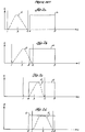
- FIG. 1 is a graphic illustration of a large signal pulse 20 which has been weighted using the constant weighting function system. The signal is plotted in both the time and frequency domain with respect to amplitude. The signal has substantial sidelobes 22 which almost completely obscure the small signal 24.
- FIG. 2A is a graphical representation of a conventional weighting function 5 as a function of amplitude and time applied to the time interval or window from time 1 to time 2. This time interval is the window of time used for sampling signal parameters.
- the vertical lines at times 4 and 8 represent the leading and trailing edge of a later occurring incoming signal pulse having an envelope 6.
- the more advanced signal weighting commonly requires an edge detector, a weighting function generator, and a multiplier.
- the edge detector analyzes the incoming signal pulses. When there is no edge, a standard weighting function 5 is applied to the window 6 (FIG 2A).
- FIG 2B represents a later time when the sampling window from time 1 to time 2 has moved in time toward the pulse and partially overlaps the pulse. The weighting function is still applied to the whole window.
- the sample window overlaps the leading edge of the pulse in time for a significant portion of the sampling window.
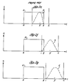
- the edge detector detects the leading edge 4 of a signal pulse and determines that the sample window 5 occupies a substantial part of the pulse envelope 6, the weighting function is only applied to the pulse envelope as illustrated by FIG. 2C to eliminate the inclusion of noise occurring before the pulse envelope.
- the weighting function is adapted to fit the signal envelope until the sample window is completely contained within the pulse envelope (FIG 2D). The signal is then weighted with the constant weighting function matched to the sample window until the sample window overlaps the trailing edge of the pulse in time.
- the edge detector detects the trailing edge 8 of a signal pulse and determines that the sample window 5 overlaps the pulse envelope
- the weighting function is only applied to the pulse envelope as illustrated by FIG 2E to eliminate the inclusion of noise occurring after the pulse envelope. This continues until the sample window is no longer overlapping a substantial part of the pulse envelope 6 after which time, the entire sample window is weighted until the next signal is detected (FIGS. 2F and 2G).
- an object of the present invention to provide a method and a respective apparatus for increasing the signal-to-noise ratio and for enhancing reception of neighboring small signals. It is a further object to significantly reduce the sidelobes thereby reducing interference from neighboring large signals.
- the weighting function is selected such that when the envelope of the signal, measured from the signal edge, is wider than a specified minimum, the envelope is weighted, but when the envelope of the signal, measured from the signal edge is narrower than the specified minimum, the space outside the signal envelope is weighted.
- a weighting function is adapted to the signal envelope of received RF pulses processed during sampling windows, according to how much of each sampling window is occupied by the signal envelope. If the signal envelope occupies a greater portion of the window than a threshold value, the weighting function is adapted to fit the envelope. If the signal envelope occupies a lesser portion of the window than the threshold value, the weighting function is adapted to fit the remainder of the window, i.e., the part of the window not occupied by the signal envelope. An edge detector determines how much of the window is occupied by the signal envelope.
- Small signals if they occur either overlapping with the leading edge of a large pulse or overlapping with the trailing edge of a large pulse, are thereby weighted independently of the large signal.
- the sample window is designed to be no longer than the shortest pulse of interest.
- the weighting functions are multiplied with the incoming signals and then sent to conventional signal processing apparatus.
- the present invention is particularly well suited to electronic warfare applications. In electronic warfare, it is important to detect and measure small signals of unknown but diverse frequencies that may be overlapping in time with the leading or trailing edge of a large signal. The present invention allows the measurement of small signals which otherwise might not be detectable.
- a preferred embodiment of the present invention is integrated into a digital electronic warfare signal receiving and processing system.
- the invention can be applied to radar, sonar, telecommunications and any other field in which signals of diverse amplitudes which overlap in time must be analyzed.
- radio waves 40 are intercepted by a receiver 42 in the form of radio frequency (RF) signal pulses.
- the receiver converts the electromagnetic signal pulses to an electrical voltage signal as is well known in the art.
- the voltage signal is then fed into an analog to digital (A/D) converter 44.
- the A/D converter samples the incoming voltage signals at a particular frequency and digitizes the voltage amplitude of each sample.
- the stream of digitized samples is fed into a first shift register 46 that has a sixty-four sample capacity.
- the shift register sends the sixty-four digitized samples on sixty-four parallel lines to an edge detector 48 which analyzes the samples within each group of sixty-four to determine whether a leading edge or a trailing edge exists within the sample window. If a leading edge or a trailing edge exists within the sample window, the edge detector determines which sample is closest to the leading edge or trailing edge and declares that sample to be the transition edge sample. The edge detector also determines whether the transition edge sample corresponds to a leading edge or a trailing edge.
- the edge detection function can be performed in a number of ways well known in the art.
- an edge detector can be designed to declare a transition edge, either a leading edge or a trailing edge, when a signal amplitude crosses a predetermined threshold. The type of edge, leading or trailing, can then be determined by testing whether the signal amplitude is increasing or decreasing.
- An algorithm in the form of a subroutine which can be used for an edge detector is attached as Exhibit A. More sophisticated edge detection algorithms can be developed. This particular one was selected for illustrative purposes due to its simplicity.
- the edge detector When the edge detector senses an edge, it signals weighting function selector logic 50 using two lines. One line indicates which sample corresponds to the edge and the other indicates whether the edge is a leading edge or a trailing edge. With this information, the logic selects a weighting function from the many weighting functions stored in a read only memory (ROM) 52.
- the stored weighting functions are conventional weighting functions known in the art, for example, Hamming functions, Hanning functions, or Blackman functions. However, they have been expanded or contracted in width to match the location of the signal edge. The adaptation of the weighting functions is described below in more detail.
- a subroutine for calculating the weighting function coefficients stored in the ROM has been attached as Exhibit B.
- the first sixty-four place shift register 46 also sends the sixty-four digitized samples to a delay 49.
- the delay compensates for the time necessary to perform the edge detection algorithm and select the proper ROM coefficients.
- the data is then sent to a second sixty-four place shift register for further processing.
- the weighting functions from the ROM 52 are sent to a multiplier 54 on sixty-four parallel lines where they are multiplied with the sixty-four digitized samples stored in the second sixty-four place shift register 56.
- the digitized, weighted signals are then sent on to conventional signal processing apparatus 56 where the signal parameters can be separated, measured, analyzed, and displayed in any number of convenient well known forms.
- each window is made up of sixty-four samples.
- the shift registers store successive overlapping windows which advance, one sample at a time. For example, if sixty-four successive samples are fed into the shift register from left to right and the samples are labeled one through sixty-four, where 1 is the earliest sample in time at the right end of the shift register and sixty-four is the most recent sample in time at the left end of the shift register, the shift register will send samples one through sixty-four to the edge detector. These same sixty-four samples, properly delayed and aligned in time with the coefficient ROM will constitute the first window of data.
- the adaptive weighting apparatus will then shift each sample one place to the right.
- the next window will therefore have samples labeled two through sixty-five. Sample one is shifted out and sample sixty-five is shifted in.
- the third window will have samples three through sixty-six, and so on.
- the windows could consist of more or fewer than sixty-four samples and successive windows could be processed with less overlap between windows, e.g., a fifty-six sample overlap as opposed to the sixty-three sample overlap described here.
- the weighting functions are selected by the logic 50 based on the location of the edge in the window as determined by the edge detector 48.
- the window consists of sixty-four samples, so the ROM is a 128 x sixty-four array.
- the places in the rows correspond to the samples in the window, and the columns correspond to possible edge locations.
- Each column of sixty-four is a set of sixty-four weighting coefficients, one coefficient for each of the sixty-four samples in the window. It requires a complete set of sixty-four samples to form a single weighting function for the sixty-four sample window.
- the 128 sets of weighting functions are all the same weighting function expanded or contracted in width. They all have the same amplitude range, but they differ in width. As explained in more detail below, the weighting function is expanded, contracted, and shifted depending on the edge location in the window. The stored weighting functions make up all the expanded, contracted, and shifted adaptations necessary to implement the invention.
- a ROM is used for speed but the weighting functions could be generated on demand or stored in some other type of device. Also, a sixty-four by sixty-four array could be used instead. Using the same weighting function for leading edges as for trailing edges, there would be one column for weighting functions for each possible leading edge location and the same columns would be used for each possible trailing edge location. Thus, only sixty-four columns would be necessary in total. If the edge were a leading edge, the weighting function would go directly to the multipliers, but if it were a trailing edge, it could be modified, for example, by reversing the order of the coefficients, before being sent to the multipliers.
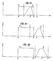
- Figures 4A - 4G show how the present invention, in a preferred embodiment, adapts and applies weighting functions.
- the window stretches from time 1 to time 2 and consists of sixty-four samples plotted on the horizontal time axis.
- the window moves from left to right on the time axis so the sample at time 2 was received first, and the sample at time 1 is the most recent.
- the amount of multiplication provided by each weighting function is indicated on the vertical amplitude axis.
- the distances from time 1 to time 3 and time 3′ to time 2 represent the minimum effective window widths.
- a minimum effective window width is necessary because, for some of the samples in the window, the weighting function will be zero.
- the samples between time 1 and time 4 will be multiplied by zero because the amplitude of the weighting function there is zero.
- the samples between time 8 and time 2 will be zeroed. While the actual window width is still the interval from time 1 to time 2, in effect, the width of the window is reduced to the interval between time 4 and time 2, and the interval between time 1 and time 8, respectively.
- the other samples have been multiplied away.
- the signal processing apparatus therefore will have a smaller data set with which to analyze the signals.
- the smaller data set will be less corrupted by a large interfering signal. Beyond a certain point, reduction of the effective window width causes too many data points to be zeroed and there is insufficient data to perform accurate analysis of the data. This point determines the minimum size of the effective window width.
- the minimum size is the number of samples received between time 1 and time 3.
- the minimum size is the number of samples received between time 1 and time .3′
- the logic selects a weighting function 5 that is spread evenly over the entire window. As the window moves toward the pulse envelope, first, a leading edge 4 and then, a trailing edge 8 will enter the window for each pulse. As an edge is detected, the weighting function is adapted to fit the edge's location in the window. The weighting function used will vary depending on the location of the edges, only one of which may be in the window at a time.
- FIG. 4B shows the weighting function 5 applied by the present invention when a leading edge enters the window. Samples received before the leading edge was received are weighted positively. Samples received after the leading edge are zeroed. This weighting function is adapted to fit the part of the window not occupied by the large signal pulse envelope 6.
- weighting functions are applied either to the whole window (FIGS. 2A, 2B, 2F, and 2G) or to the signal envelope (FIGS. 2C to 2E).
- This increases the signal to noise ratio (SNR) by removing samples which consist only of noise without any signal.
- SNR signal to noise ratio
- the present invention by weighting samples taken before the leading edge was received boosts the small signal, if one, exists, so that it can also be measured in the conventional signal processing apparatus. As the window moves toward the pulse envelope, the weighting function is contracted to fit the part of the window remaining between the leading edge 4 and time 1 of the window (FIG. 4B).
- the invention continues to weight the samples outside the leading edge of the pulse envelope until point 3 reaches the leading edge. If the invention continued to weight the samples before the leading edge, the effective window width from point 1 to point 4 would be less than the minimum effective window width from point 1 to point 3.
- the weighting function 5 is switched to the window space following the leading edge (FIG. 4C).
- the large signal envelope in the window is weighted and signals in the remainder of the window are zeroed.
- the large signal envelope occupies more of the window.
- the weighting function is expanded to fill this space until the entire window is within the large signal envelope. The entire window is then weighted (FIG. 4D).
- the trailing edge 8 After the leading edge exits the window, the trailing edge 8 enters (FIG. 4E).
- the window width from 1 to 2 is selected to be no longer than the shortest anticipated pulse envelope of the signals to be analyzed. Therefore, the trailing edge 8 is never in the window at the same time as the leading edge 4.
- the weighting function is contracted so that only the large signal envelope is weighted.
- the weighting function continues to contract until the trailing edge passes the minimum window width point 3′.
- the weighting function is then shifted (FIG. 4F).
- the minimum effective window width parameter in FIGS. 4E through 4G has been renumbered from 3 to 3′ because the minimum window width refers to the minimum width acceptable before the shift from zeroing the data from the large signal pulse envelope to zeroing the data from outside the large pulse envelope occurs.
- the point at which the switch occurs will typically be different for the leading and trailing edges. For example, if the minimum window width were twenty with a sample window width of sixty-four, then for the leading edge, point 3 would be at twenty while for the trailing edge, point 3′ would be at forty-four. In the present embodiment, however, the minimum number of nonzero samples has been chosen to be one half the total or thirty-two samples, so point 3 and 3′ are concurrent.
- the present invention weights only the samples received after the trailing edge 8, while zeroing the large signal envelope. This represses the large signal sidelobes and allows smaller signals, if any, received near the trailing edge, to be detected and measured.
- the weighting function is expanded, continuing to weight all of the samples following the trailing edge until the trailing edge exits the window. After the trailing edge exits the window, the weighting function is again applied to the entire window until a new edge is detected (FIG. 4G).
- the weighting function expands and contracts between the full window width and the user selected minimum window width.
- the width of the weighting function matches the width of the sample window when the pulse envelope lies totally outside the window.
- the weighting function contracts in the portion of the window occupied by the pulse envelope until the weighting function is contracted to the minimum window width.
- the weighting function switches to occupy the same portion of the window as the pulse envelope and expands with the pulse envelope until it occupies the entire window.
- the weighting function occupying the same portion of the window as the pulse envelope, contracts until the weighting function is contracted to the minimum window width. Thereupon, the weighting function again switches to the portion of the window unoccupied by the pulse envelope and expands until the pulse envelope leaves the window entirely.
- the preferred embodiment is adapted specifically for electronic warfare.
- the windows contain sixty-four samples each, and sampling is done at 1,280 MHz, so the window is 50 nanoseconds long.
- the signal processing system must handle signal pulses no shorter than 100 nanoseconds long.
- the selected minimum effective window length is one half the actual window length, or 32 samples and 25 nanoseconds long.
- FIG. 5 demonstrates the substantial improvement in small signal detection achieved by the present invention as compared to the prior art constant weighting approach (FIG. 1).
- the same two signals, overlapping in time and close in frequency, but very different in amplitude have been plotted as a function of time, frequency, and amplitude in both figures.
- the smaller signal 24 is almost entirely obscured by the sidelobes 22 of the large signal 20.
- the sidelobes 22 are greatly reduced and the small signal 24 is readily apparent.
- the region for Case A corresponds to when the window space before the leading edge is weighted (FIGS. 4A and 4B).
- Case B corresponds to when the large signal envelope is weighted (FIGS. 4C through 4E).
- Case C corresponds to when the window space after the trailing edge is weighted (FIGS. 4F through 4G).
- FIGURE 1 also shows how the sidelobes become superimposed on the small signal distorting its basic shape.
- the present invention as shown in FIG. 5, the long, large sidelobes have much less effect on the small signal. Therefore, the small signal's parameters can be determined with greater accuracy.
- a subroutine which executes the adaptive weighting of the present invention is attached as Exhibit C.
- the present invention can be simplified by reducing the number of sets of weighting coefficients applied to the samples.
- the edge detector could be designed to detect the edge to within a region of four sample points. The edge could then lie in only one of sixteen possible four sample regions.
- the array of weighting functions could then be as small as a sixteen x sixty-four array. There would be sixteen columns, one for each possible edge location, and sixty-four weighting multipliers, one to be multiplied by each of the sixty-four data samples in the sample window.
- This example would also require the use of the reversal technique described earlier to account for the leading and trailing edge cases.
- This type of simplification allows the invention to operate much faster, an advantage with high sampling rates. The reduced resolution caused by using fewer sets of weighting functions would not be significant in most applications.
Landscapes
- Physics & Mathematics (AREA)
- General Physics & Mathematics (AREA)
- Engineering & Computer Science (AREA)
- Computer Networks & Wireless Communication (AREA)
- Signal Processing (AREA)
- Power Engineering (AREA)
- Radar Systems Or Details Thereof (AREA)
- Noise Elimination (AREA)
- Digital Transmission Methods That Use Modulated Carrier Waves (AREA)
- Circuits Of Receivers In General (AREA)
- Measuring Frequencies, Analyzing Spectra (AREA)
- Complex Calculations (AREA)
Claims (11)
- Vorrichtung zur Anwendung von Gewichtungsfunktionen (5) auf Signale (6) innerhalb eines Fensters in einem Signal-Verarbeitungssystem, enthaltend1.1 eine Quelle (52) von Gewichtungsfunktionen;1.2 einen Flankendetektor (48) für die Bestimmung des Ortes einer Flanke (4, 8) eines detektierten Signals (6) innerhalb eines Fensters;1.3 Mittel (46, 48, 50) für die Auswahl einer Gewichtungsfunktion von genannter Quelle (52) von Gewichtungsfunktionen, basierend auf dem Ort der Signalflanke (4, 8); und1.4 Mittel (49, 54, 56) für die Anwendung der ausgewählten Gewichtungsfunktion auf das Fenster,dadurch gekennzeichnet, daß1.5 die Gewichtungsfunktion so ausgewählt wird, daß zumindest für einige Zeit derjenige Fensterbereich, welcher im wesentlichen die Einhüllende des detektierten Signals (6) ausschließt, mehr gewichtet wird, als derjenige Fensterbereich, welcher im wesentlichen die Einhüllende des detektierten Signals (6) einschließt,1.6 genannte Mittel (46, 48, 50) für die Auswahl einer Gewichtungsfunktion Mittel (50) enthalten für die Feststellung, ob die Einhüllende einen größeren oder einen geringeren Teil des Fensters einnimmt, als es einem Schwellwert entspricht, und1.7 genanntes Mittel (50) für die Auswahl der Gewichtungsfunktion diejenige Gewichtungsfunktion auswählt, welche in den Teil des Fensters hineinpaßt, der nicht durch die Einhüllende eingenommen ist, wenn die Einhüllende einen geringeren Teil des Fensters einnimmt, als es einem Schwellwert entspricht, und in den Teil des Fensters hineinpaßt, der durch die Einhüllende eingenommen ist, wenn die Einhüllende einen größeren Teil des Fensters einnimmt, als es einem Schwellwert entspricht.
- Vorrichtung nach Anspruch 1, wobei genannte Signale (6) Radio-Frequenz-Signale (6) sind,
gekennzeichnet durch2.1 Mittel (42) für das Auffangen der genannten Radio-Frequenz-Signale (6);2.2 Mittel (44) zum Abtasten der Einhüllenden des Radio-Frequenz-Signals (6) während aufeinanderfolgender Abtastfenster;und weiterhin dadurch gekennzeichnet, daß2.3 die genannte Quelle von Gewichtungsfunktionen Mittel für die Speicherung einer auf die Abtastwerte anzuwendenden Gewichtungsfunktion umfaßt. - Vorrichtung nach Anspruch 2, insbesondere für die Verarbeitung von im wesentlichen gleichzeitig auftretenden Radio-Frequenz-Signalen (6),
dadurch gekennzeichnet, daß3.1 genanntes Mittel (42) für das Auffangen eines Radio-Frequenz-Signals (6) ein Empfänger für Radio-Frequenz-Signale ist;3.2 genanntes Mittel (44) für das Abtasten der Einhüllenden des Radio-Frequenz-Signales (6) ein AnalogDigital-Wandler ist;3.3 genannte Mittel (46, 48, 50) für die Auswahl einer Gewichtungsfunktion auf Flanken (4, 8) ansprechen, die durch den Flankendetektor (48) detektiert werden, so daß die Abtastwerte innerhalb einer Gruppe von Abtastwerten, welche außerhalb der Signaleinhüllenden der detektierten Signalflanke (4, 8) sind, für zumindest einige Flankenorte stärker gewichtet werden als Abtastwerte innerhalb einer Gruppe von Abtastwerten, welche innerhalb der Signaleinhüllenden der detektierten Signalflanke (4, 8) sind;3.4 genannte Mittel (49, 54, 56) für die Anwendung der ausgewählten Gewichtungsfunktion Mittel (54) enthalten für die Multiplikation der Gruppe von Abtastwerten mit der Gewichtungsfunktion, welche durch die Mittel (46, 48, 50) für die Auswahl der Gewichtungsfunktion ausgewählt ist,und weiterhin gekennzeichnet durch3.5 einen Umsetzer für die Wandlung der Radio-Frequenz-Signale (6) in Spannungssignale, und3.6 ein Schiebregister (46) für die Aufnahme einer Gruppe von Abtastwerten. - Vorrichtung nach einem der Ansprüche 1 bis 3, dadurch gekennzeichnet, daß genannte Mittel (49, 54, 56) für die Anwendung der ausgewählten Gewichtungsfunktion Mittel (49) enthalten für die Verzögerung der Signale (6), auf welche die Gewichtungsfunktionen angewandt werden, bis eine Gewichtungsfunktion ausgewählt worden ist.
- Vorrichtung nach einem der vorherigen Ansprüche, dadurch gekennzeichnet, daß genannte Quelle von Gewichtungsfunktionen ein Speicherarray (52) ist.
- Vorrichtung nach Anspruch 5, dadurch gekennzeichnet, daß genanntes Speicherarray (52) zumindest zweidimensional ist, wobei eine Dimension dem Flankenort und die andere Dimension Koeffizienten der verschiedenen Gewichtungsfunktionen entspricht.
- Vorrichtung nach Anspruch 5 oder 6, dadurch gekennzeichnet, daß genanntes Speicherarray (52) ein Array mit wahlfreiem Zugriff ist.
- Vorrichtung nach einem der vorherigen Ansprüche, dadurch gekennzeichnet, daß genannter Flankendetektor (48) zwischen vorderen (4) und hinteren (8) Flanken unterscheidet, und daß genannte Mittel (46, 48, 50) für die Auswahl einer Gewichtungsfunktion eine Gewichtungsfunktion in Übereinstimmung mit dieser Unterscheidung auswählen.
- Vorrichtung nach einem der vorherigen Ansprüche, dadurch gekennzeichnet, daß genannte Signale (6) in digitale Datenabtastwerte gewandelt sind und die Elemente der Vorrichtung digital arbeiten.
- Vorrichtung nach einem der Ansprüche 5 bis 9, dadurch gekennzeichnet, daß10.1 das Fenster eine Vielzahl von Datenabtastwerten enthält,10.2 das Speicherarray (52) zumindest so viele Gewichtungsfunktionen beinhaltet, wie es Datenabtastwerte gibt, zumindest einen für jeden möglichen Ort der Flanke in dem Fenster, und10.3 jede Gewichtungsfunktion zumindest so viele Koeffizienten enthält, wie es Datenabtastwerte gibt, zumindest einen für jeden Datenabtastwert in dem Fenster.
- Verfahren zur Anwendung von Gewichtungsfunktionen auf Signale (6), mit den Schritten:11.1 Bestimmung des Ortes einer Signalflanke (4, 8) innerhalb eines Fensters von Abtastwerten;11.2 Selektierung einer Gewichtungsfunktion; und11.3 Anwendung der selektierten Gewichtungsfunktion auf das Signal (6) innerhalb des Fensters,dadurch gekennzeichnet, daß in Schritt 11.2 die Gewichtungsfunktion in der Weise ausgewählt wird, daß die Einhüllende gewichtet wird, wenn gemessen von der Signalflanke (4, 8) die Einhüllende des Signals (6) breiter als ein spezifiziertes Minimum ist, aber der Bereich außerhalb der Signaleinhüllenden gewichtet wird, wenn die Einhüllende des Signals (6) gemessen von der Signalflanke (4, 8) schmaler als ein spezifiziertes Minimum ist.
Applications Claiming Priority (2)
| Application Number | Priority Date | Filing Date | Title |
|---|---|---|---|
| US07/201,795 US4984253A (en) | 1988-06-03 | 1988-06-03 | Apparatus and method for processing simultaneous radio frequency signals |
| US201795 | 1994-02-25 |
Publications (3)
| Publication Number | Publication Date |
|---|---|
| EP0344794A2 EP0344794A2 (de) | 1989-12-06 |
| EP0344794A3 EP0344794A3 (de) | 1991-01-09 |
| EP0344794B1 true EP0344794B1 (de) | 1994-11-09 |
Family
ID=22747331
Family Applications (1)
| Application Number | Title | Priority Date | Filing Date |
|---|---|---|---|
| EP89110013A Expired - Lifetime EP0344794B1 (de) | 1988-06-03 | 1989-06-02 | Anordnung und Verfahren zur Behandlung von gleichzeitigen Radio-Frequenz-Signalen |
Country Status (9)
| Country | Link |
|---|---|
| US (1) | US4984253A (de) |
| EP (1) | EP0344794B1 (de) |
| JP (1) | JPH0265311A (de) |
| KR (1) | KR920005163B1 (de) |
| AU (1) | AU597529B2 (de) |
| CA (1) | CA1320536C (de) |
| DE (1) | DE68919279T2 (de) |
| ES (1) | ES2063782T3 (de) |
| IL (1) | IL90253A (de) |
Families Citing this family (11)
| Publication number | Priority date | Publication date | Assignee | Title |
|---|---|---|---|---|
| EP0427953B1 (de) * | 1989-10-06 | 1996-01-17 | Matsushita Electric Industrial Co., Ltd. | Einrichtung und Methode zur Veränderung von Sprechgeschwindigkeit |
| JP2909159B2 (ja) * | 1990-07-10 | 1999-06-23 | アンリツ株式会社 | 平滑化処理方法および平滑化処理による雑音除去装置およびそれを用いる光パルス試験装置 |
| FR2672453B1 (fr) * | 1991-01-31 | 1993-04-09 | Alcatel Telspace | Procede de detection de signal perturbateur pour demodulateur de donnees numeriques et dispositif de mise en óoeuvre d'un tel procede. |
| US6014413A (en) * | 1997-05-02 | 2000-01-11 | At&T Corp | Time-shifted weighting for signal processing |
| US9588213B2 (en) | 2014-02-18 | 2017-03-07 | Raytheon Company | Analog signal processing method for accurate single antenna direction finding |
| US9590760B2 (en) | 2014-06-03 | 2017-03-07 | Raytheon Company | Analog RF memory system |
| US9645972B2 (en) | 2014-06-16 | 2017-05-09 | Raytheon Company | Butterfly channelizer |
| US9485125B2 (en) | 2014-06-16 | 2016-11-01 | Raytheon Company | Dynamically reconfigurable channelizer |
| US10027026B2 (en) | 2014-09-18 | 2018-07-17 | Raytheon Company | Programmable beamforming system including element-level analog channelizer |
| US10348338B2 (en) | 2016-10-06 | 2019-07-09 | Raytheon Company | Adaptive channelizer |
| US10084587B1 (en) | 2017-07-28 | 2018-09-25 | Raytheon Company | Multifunction channelizer/DDC architecture for a digital receiver/exciter |
Family Cites Families (21)
| Publication number | Priority date | Publication date | Assignee | Title |
|---|---|---|---|---|
| FR1188828A (fr) * | 1957-12-19 | 1959-09-25 | Csf | Perfectionnements aux dispositifs de protection d'un récepteur à impulsions |
| US3877011A (en) * | 1967-10-26 | 1975-04-08 | Hughes Aircraft Co | Dual channel adaptable moving target processor |
| US3877010A (en) * | 1967-10-26 | 1975-04-08 | Hughes Aircraft Co | Adaptable moving target processor |
| AU503919B2 (en) * | 1975-09-16 | 1979-09-27 | Broken Hill Proprietary Company Limited, The | Signal stabilising circuits |
| US4038539A (en) * | 1976-02-23 | 1977-07-26 | American Electronic Laboratories, Inc. | Adaptive pulse processing means and method |
| US4070673A (en) * | 1976-09-03 | 1978-01-24 | Sperry Rand Corporation | Radar video digital processor |
| US4093989A (en) * | 1976-12-03 | 1978-06-06 | Rockland Systems Corporation | Spectrum analyzer using digital filters |
| JPS5625819A (en) * | 1979-08-09 | 1981-03-12 | Toshiba Corp | Digital coefficient circuit |
| US4302845A (en) * | 1980-02-07 | 1981-11-24 | Motorola, Inc. | Phase-encoded data signal demodulator |
| US4281318A (en) * | 1980-05-30 | 1981-07-28 | Bell Telephone Laboratories, Incorporated | Digital-to-digital code converter |
| DE3033382C2 (de) * | 1980-09-04 | 1982-06-09 | Siemens AG, 1000 Berlin und 8000 München | Puls-Doppler-Radar mit einer von Rekursionsfiltern gebildeten Festzeichenunterdrückungsschaltung |
| US4385208A (en) * | 1981-04-15 | 1983-05-24 | Bell Telephone Laboratories, Incorporated | Multifrequency receiver |
| GB2191052B (en) * | 1981-10-28 | 1988-05-25 | Emi Ltd | Radar apparatus |
| US4536764A (en) * | 1982-09-29 | 1985-08-20 | Westinghouse Electric Corp. | Method of counting multiple targets in the post detection processing of a radar |
| JPS59210512A (ja) * | 1983-05-13 | 1984-11-29 | Hitachi Ltd | デイジタル信号再生回路 |
| US4672638A (en) * | 1983-10-24 | 1987-06-09 | Nec Corporation | Multipath canceller for cancelling a distortion caused to a radio frequency pulse by multipath transmission |
| US4608567A (en) * | 1984-06-22 | 1986-08-26 | The United States Of America As Represented By The Secretary Of The Air Force | Fast envelope detector with bias compensation |
| JPS6182520A (ja) * | 1984-09-29 | 1986-04-26 | Toshiba Corp | デジタルフイルタ回路 |
| JPS6245209A (ja) * | 1985-08-23 | 1987-02-27 | Canon Inc | エツジ検出フイルタ |
| US4669091A (en) * | 1986-02-10 | 1987-05-26 | Rca Corporation | Adaptive multipath distortion equalizer |
| US4958361A (en) * | 1988-04-22 | 1990-09-18 | Hughes Aircraft Company | Edge effect reduction by smoothing in digital receivers |
-
1988
- 1988-06-03 US US07/201,795 patent/US4984253A/en not_active Expired - Fee Related
-
1989
- 1989-05-10 CA CA000599342A patent/CA1320536C/en not_active Expired - Fee Related
- 1989-05-11 IL IL90253A patent/IL90253A/xx not_active IP Right Cessation
- 1989-05-19 AU AU34996/89A patent/AU597529B2/en not_active Ceased
- 1989-06-02 DE DE68919279T patent/DE68919279T2/de not_active Expired - Fee Related
- 1989-06-02 JP JP1140924A patent/JPH0265311A/ja active Pending
- 1989-06-02 EP EP89110013A patent/EP0344794B1/de not_active Expired - Lifetime
- 1989-06-02 ES ES89110013T patent/ES2063782T3/es not_active Expired - Lifetime
- 1989-06-02 KR KR1019890007712A patent/KR920005163B1/ko not_active IP Right Cessation
Also Published As
| Publication number | Publication date |
|---|---|
| DE68919279D1 (de) | 1994-12-15 |
| ES2063782T3 (es) | 1995-01-16 |
| KR900001145A (ko) | 1990-01-31 |
| EP0344794A3 (de) | 1991-01-09 |
| US4984253A (en) | 1991-01-08 |
| AU3499689A (en) | 1989-12-07 |
| CA1320536C (en) | 1993-07-20 |
| DE68919279T2 (de) | 1995-03-23 |
| IL90253A0 (en) | 1989-12-15 |
| AU597529B2 (en) | 1990-05-31 |
| IL90253A (en) | 1993-07-08 |
| KR920005163B1 (ko) | 1992-06-27 |
| EP0344794A2 (de) | 1989-12-06 |
| JPH0265311A (ja) | 1990-03-06 |
Similar Documents
| Publication | Publication Date | Title |
|---|---|---|
| EP0932837B1 (de) | Verfahren zur störungsunterdrückung in einem fmcw-radar | |
| EP1672379B1 (de) | System und Verfahren zur Verminderung eines Radarstörsignals | |
| EP0344794B1 (de) | Anordnung und Verfahren zur Behandlung von gleichzeitigen Radio-Frequenz-Signalen | |
| US6296612B1 (en) | Method and apparatus for adaptive wall filtering in spectral Doppler ultrasound imaging | |
| US5075619A (en) | Method and apparatus for measuring the frequency of a spectral line | |
| US5901348A (en) | Apparatus for enhancing sensitivity in compressive receivers and method for the same | |
| EP2570782B1 (de) | Doppler-Messinstrument und Doppler-Messverarbeitungsverfahren | |
| EP0654666A1 (de) | Verfahren und vorrichtung zur verarbeitung von signalen eines ultraschallfehlerdetektors | |
| EP0395863B1 (de) | Apertursynthetisiertes Radiometer, welches digitale Strahlenbündelungstechnik verwendet | |
| KR930010562A (ko) | 합성 어레이 레이다에서의 포커스 에러의 자동 보정 방법 | |
| US4231103A (en) | Fast Fourier transform spectral analysis system employing adaptive window | |
| KR100459616B1 (ko) | 도플러 효과를 이용하여 인체 조직 속도를 측정하기 위한초음파 진단 장치 및 방법 | |
| JPH0566268A (ja) | デイジタル・パルス圧縮装置 | |
| US10859691B2 (en) | Radar range accuracy improvement method | |
| WO1993011581A1 (en) | Method for field monitoring of a phased array microwave landing system far field antenna pattern employing a near field correction technique | |
| US20140351302A1 (en) | Precision Measurement of Waveforms | |
| US20070118317A1 (en) | System and method for generating triggers based on predetermined trigger waveform and a measurement signal | |
| US4328497A (en) | Method and system for jamming analysis and transmission selection | |
| US4084148A (en) | Object recognition system | |
| JP4723880B2 (ja) | 電波誘導装置 | |
| JP6837379B2 (ja) | 部分放電検出装置および部分放電検出方法 | |
| CN111812404B (zh) | 一种信号处理方法以及处理装置 | |
| EP0343370A2 (de) | Randeffekt-Reduktion durch Glättung in digitalen Empfängern | |
| EP0486096B1 (de) | Unterdrückung des Überfaltungsartefaktes in Puls-Dopplersystemen | |
| JP5603090B2 (ja) | レーダ信号処理装置 |
Legal Events
| Date | Code | Title | Description |
|---|---|---|---|
| PUAI | Public reference made under article 153(3) epc to a published international application that has entered the european phase |
Free format text: ORIGINAL CODE: 0009012 |
|
| 17P | Request for examination filed |
Effective date: 19890616 |
|
| AK | Designated contracting states |
Kind code of ref document: A2 Designated state(s): CH DE ES FR GB IT LI SE |
|
| PUAL | Search report despatched |
Free format text: ORIGINAL CODE: 0009013 |
|
| AK | Designated contracting states |
Kind code of ref document: A3 Designated state(s): CH DE ES FR GB IT LI SE |
|
| RHK1 | Main classification (correction) |
Ipc: G01S 7/28 |
|
| 17Q | First examination report despatched |
Effective date: 19930720 |
|
| GRAA | (expected) grant |
Free format text: ORIGINAL CODE: 0009210 |
|
| AK | Designated contracting states |
Kind code of ref document: B1 Designated state(s): CH DE ES FR GB IT LI SE |
|
| REF | Corresponds to: |
Ref document number: 68919279 Country of ref document: DE Date of ref document: 19941215 |
|
| ITF | It: translation for a ep patent filed |
Owner name: SOCIETA' ITALIANA BREVETTI S.P.A. |
|
| REG | Reference to a national code |
Ref country code: ES Ref legal event code: FG2A Ref document number: 2063782 Country of ref document: ES Kind code of ref document: T3 |
|
| EAL | Se: european patent in force in sweden |
Ref document number: 89110013.3 |
|
| ET | Fr: translation filed | ||
| PLBE | No opposition filed within time limit |
Free format text: ORIGINAL CODE: 0009261 |
|
| STAA | Information on the status of an ep patent application or granted ep patent |
Free format text: STATUS: NO OPPOSITION FILED WITHIN TIME LIMIT |
|
| 26N | No opposition filed | ||
| REG | Reference to a national code |
Ref country code: GB Ref legal event code: 732E |
|
| REG | Reference to a national code |
Ref country code: ES Ref legal event code: PC2A |
|
| REG | Reference to a national code |
Ref country code: FR Ref legal event code: TP Ref country code: FR Ref legal event code: CD Ref country code: FR Ref legal event code: CA |
|
| PGFP | Annual fee paid to national office [announced via postgrant information from national office to epo] |
Ref country code: FR Payment date: 20000511 Year of fee payment: 12 |
|
| PGFP | Annual fee paid to national office [announced via postgrant information from national office to epo] |
Ref country code: SE Payment date: 20000519 Year of fee payment: 12 |
|
| PGFP | Annual fee paid to national office [announced via postgrant information from national office to epo] |
Ref country code: CH Payment date: 20000522 Year of fee payment: 12 |
|
| PGFP | Annual fee paid to national office [announced via postgrant information from national office to epo] |
Ref country code: GB Payment date: 20000523 Year of fee payment: 12 |
|
| PGFP | Annual fee paid to national office [announced via postgrant information from national office to epo] |
Ref country code: DE Payment date: 20000524 Year of fee payment: 12 |
|
| PGFP | Annual fee paid to national office [announced via postgrant information from national office to epo] |
Ref country code: ES Payment date: 20000607 Year of fee payment: 12 |
|
| PG25 | Lapsed in a contracting state [announced via postgrant information from national office to epo] |
Ref country code: GB Free format text: LAPSE BECAUSE OF NON-PAYMENT OF DUE FEES Effective date: 20010602 |
|
| PG25 | Lapsed in a contracting state [announced via postgrant information from national office to epo] |
Ref country code: SE Free format text: LAPSE BECAUSE OF NON-PAYMENT OF DUE FEES Effective date: 20010603 |
|
| PG25 | Lapsed in a contracting state [announced via postgrant information from national office to epo] |
Ref country code: ES Free format text: LAPSE BECAUSE OF NON-PAYMENT OF DUE FEES Effective date: 20010604 |
|
| PG25 | Lapsed in a contracting state [announced via postgrant information from national office to epo] |
Ref country code: LI Free format text: LAPSE BECAUSE OF NON-PAYMENT OF DUE FEES Effective date: 20010630 Ref country code: CH Free format text: LAPSE BECAUSE OF NON-PAYMENT OF DUE FEES Effective date: 20010630 |
|
| GBPC | Gb: european patent ceased through non-payment of renewal fee |
Effective date: 20010602 |
|
| EUG | Se: european patent has lapsed |
Ref document number: 89110013.3 |
|
| REG | Reference to a national code |
Ref country code: CH Ref legal event code: PL |
|
| PG25 | Lapsed in a contracting state [announced via postgrant information from national office to epo] |
Ref country code: FR Free format text: LAPSE BECAUSE OF NON-PAYMENT OF DUE FEES Effective date: 20020228 |
|
| PG25 | Lapsed in a contracting state [announced via postgrant information from national office to epo] |
Ref country code: DE Free format text: LAPSE BECAUSE OF NON-PAYMENT OF DUE FEES Effective date: 20020403 |
|
| REG | Reference to a national code |
Ref country code: ES Ref legal event code: FD2A Effective date: 20030303 |
|
| PG25 | Lapsed in a contracting state [announced via postgrant information from national office to epo] |
Ref country code: IT Free format text: LAPSE BECAUSE OF NON-PAYMENT OF DUE FEES;WARNING: LAPSES OF ITALIAN PATENTS WITH EFFECTIVE DATE BEFORE 2007 MAY HAVE OCCURRED AT ANY TIME BEFORE 2007. THE CORRECT EFFECTIVE DATE MAY BE DIFFERENT FROM THE ONE RECORDED. Effective date: 20050602 |