US6296612B1 - Method and apparatus for adaptive wall filtering in spectral Doppler ultrasound imaging - Google Patents
Method and apparatus for adaptive wall filtering in spectral Doppler ultrasound imaging Download PDFInfo
- Publication number
- US6296612B1 US6296612B1 US09/349,586 US34958699A US6296612B1 US 6296612 B1 US6296612 B1 US 6296612B1 US 34958699 A US34958699 A US 34958699A US 6296612 B1 US6296612 B1 US 6296612B1
- Authority
- US
- United States
- Prior art keywords
- frequency
- mean
- clutter
- wall
- low pass
- Prior art date
- Legal status (The legal status is an assumption and is not a legal conclusion. Google has not performed a legal analysis and makes no representation as to the accuracy of the status listed.)
- Expired - Fee Related
Links
Images


Classifications
-
- G—PHYSICS
- G01—MEASURING; TESTING
- G01S—RADIO DIRECTION-FINDING; RADIO NAVIGATION; DETERMINING DISTANCE OR VELOCITY BY USE OF RADIO WAVES; LOCATING OR PRESENCE-DETECTING BY USE OF THE REFLECTION OR RERADIATION OF RADIO WAVES; ANALOGOUS ARRANGEMENTS USING OTHER WAVES
- G01S15/00—Systems using the reflection or reradiation of acoustic waves, e.g. sonar systems
- G01S15/88—Sonar systems specially adapted for specific applications
- G01S15/89—Sonar systems specially adapted for specific applications for mapping or imaging
- G01S15/8906—Short-range imaging systems; Acoustic microscope systems using pulse-echo techniques
- G01S15/8979—Combined Doppler and pulse-echo imaging systems
- G01S15/8981—Discriminating between fixed and moving objects or between objects moving at different speeds, e.g. wall clutter filter
-
- A—HUMAN NECESSITIES
- A61—MEDICAL OR VETERINARY SCIENCE; HYGIENE
- A61B—DIAGNOSIS; SURGERY; IDENTIFICATION
- A61B8/00—Diagnosis using ultrasonic, sonic or infrasonic waves
- A61B8/06—Measuring blood flow
Definitions
- This invention relates to ultrasonic diagnostic systems which measure the velocity of blood flow using spectral Doppler techniques.
- the invention relates to the continuous display of such information, including maximum and mean blood flow velocities.
- Ultrasonic scanners for detecting blood flow based on the Doppler effect are well known. Such systems operate by actuating an ultrasonic transducer array to transmit ultrasonic waves into the object and receiving ultrasonic echoes backscattered from the object. For blood flow measurements, returning ultrasonic waves are compared to a frequency reference to determine the frequency shifts imparted to the returning waves by moving objects including the vessel walls and the red blood cells inside the vessel. These frequency shifts translate into velocities of motion.
- the pulsed or continuous wave Doppler waveform is com- puted and displayed in real-time as a gray-scale spectrogram of velocity versus time with the gray-scale intensity (or color) modulated by the spectral power.
- the data for each spectral line comprises a multiplicity of frequency data bins for different frequency intervals, the spectral power data in each bin for a respective spectral line being displayed in a respective pixel of a respective column of pixels on the display monitor.
- Each spectral line represents an instantaneous measurement of blood flow.
- an ultrasound transducer array is activated to transmit by a transmit ultrasound burst which is fired repeatedly at a pulse repetition frequency (PRF).
- PRF pulse repetition frequency
- the PRF is typically in the kilohertz range.
- the return radiofrequency (RF) signals are detected by the transducer elements and then formed into a receive beam by a beamformer.
- the summed RF signal from each firing is demodulated by a demodulator into its in-phase and quadrature (I/Q) components.
- the I/Q components are integrated (summed) over a specific time interval and then sampled.
- the summing interval and transmit burst length together define the length of the sample volume as specified by the user.
- the Doppler signal is passed through a wall filter, which is a high pass filter that rejects any clutter in the signal corresponding to stationary or very slow-moving tissue, including a portion of the vessel wall(s) that might be lying within the sample volume.
- the filtered output is then fed into a spectrum analyzer, which typically takes the complex Fast Fourier Transform (FFT) over a moving time window of 64 to 256 samples.
- FFT Fast Fourier Transform
- the data samples within an FFT analysis time window will be referred to hereinafter as an FFT packet.
- Each FFT power spectrum is compressed and then displayed via a gray map on the monitor as a single spectral line at a particular time point in the Doppler velocity (frequency) versus time spectrogram.
- the I and Q components of the Doppler signal are filtered separately by identical wall filters, which can be implemented as either an FIR or IIR filter.
- wall filters For s harp rejection of low-frequency clutter, a narrow transition band in the frequency response of the filter is required.
- the wall filter cutoff frequency is manually selected via a front-panel control key. Usually the wall filter cutoff frequency is increased when bright, low-frequency clutter is seen in the spectral image.
- LUT lookup table
- the main limitation with the manually selected filter approach in the prior art is that once the cutoff frequency is set, the wall filter does not change even though the clutter frequency and bandwidth may vary with time, due to radial and/or lateral motion of the vessel walls over the cardiac cycle. As a result, the selected filter cutoff is often optimal only for a small portion of the cardiac cycle.
- the present invention is a method and an apparatus for adaptive wall (high-pass) filtering which overcomes the limitation of the prior art manually selected filter approach.
- the wall filter cutoff frequency is selected automatically, thereby improving ease of use and productivity.
- a further advantage is that a wall filter cutoff frequency tailored to each new FFT packet can be used.
- low-frequency clutter is removed in the Doppler I/Q data prior to FFT processing.
- the I/Q data is passed through a low-pass filter whose cutoff frequency is set at the highest anticipated clutter frequency (e.g. 40% of PRF) for the current Doppler application.
- the low-pass filter rejects the flow frequency components above the clutter frequency range.
- the total power of the low-pass filter output i.e., the sum of (I n 2 +Q n 2 ) over the FFT (or a fraction of the FFT) packet size M, is then computed.
- a system noise model is used to predict the mean system noise power in the low-pass filter output.
- the mean system noise power predicted by the system noise model provides a noise threshold to gage how much clutter power is present in the current FFT packet. If no significant clutter is present, then wall filter selection logic will automatically select the lowest wall filter cutoff frequency in a filter coefficient LUT. If significant clutter power is present in the FFT packet, the algorithm proceeds to compute the mean and variance of the clutter frequency over the FFT packet. The estimated mean and variance of the clutter frequency are then fed into the filter selection logic, which selects the most suitable filter cutoff for the current clutter signal.
- FIG. 1 is a block diagram of the basic signal processing chain in a conventional spectral Doppler imaging system.
- FIG. 2 is a block diagram showing a wall filter and associated components of a spectral Doppler imaging system of the type depicted in FIG. 1 .
- FIG. 3 is a flowchart showing the preferred embodiment of the invention.
- FIG. 1 A typical digital real-time ultrasonic imaging system having a spectral Doppler imaging mode is generally depicted in FIG. 1 .
- An ultrasound transducer array 2 is activated by a transmitter of a beamformer 4 to transmit ultrasound beams focused at a desired transmit focal position.
- the transmitter provides a transmit ultrasound burst which is fired repeatedly at a pulse repetition frequency (PRF).
- PRF pulse repetition frequency
- the PRF is typically in the kilohertz range.
- the return RF signals are detected by the transducer elements and then formed into a receive beam by a receiver of beamformer 4 .
- the summed (beamformed) RF signal from each firing is demodulated by demodulator 6 into its in-phase and quadrature (I/Q) components.
- the I/Q components are integrated (summed) over a specific time interval and then sampled by a “sum and dump” block 8 .
- the summing interval and transmit burst length together define the length of the sample volume as specified by the user.
- the “sum and dump” operation effectively yields the Doppler signal backscattered from the sample volume.
- the Doppler signal is passed through a wall filter 10 which rejects any clutter in the signal corresponding to stationary or very slow-moving tissue.
- the filtered output is then fed into a spectrum analyzer 12 , which typically takes the Fast Fourier Transform (FFT) over a moving time window of 64 to 256 samples.
- FFT Fast Fourier Transform
- Each FFT power spectrum is compressed (block 14 ) and mapped (block 16 ) to a gray scale for display on monitor 18 as a single spectral line at a particular time point in the Doppler velocity (frequency) versus time spectrogram.
- the I and Q components of the Doppler signal are filtered separately by identical wall filters, which can be implemented as either an FIR or IIR filter.
- a narrow transition band in the frequency response of the filter is required.
- IIR filters are generally considered more advantageous because of the large filter length required of an FIR implementation.
- an IIR high-pass filter is usually used, and it is often implemented as a cascade of three or four second-order stages. The input x(n) and the output y(n) of each second-order stage satisfy the following difference equation:
- y(n) a 1 y(n ⁇ 1)+a 2 y(n ⁇ 2)+b 0 x(n)+b 1 x(n ⁇ 1)+d 2 x(n ⁇ 2)
- the filter coefficients ⁇ a 1 ,a 2 ,b 0 ,b 1 ,b 2 ⁇ for each second-order stage can be pre-computed using standard filter design formulas and stored in a LUT 22 (see FIG. 2 ).
- the wall filter cutoff frequency is manually selected via a front-panel control key 20 .
- the wall filter cutoff frequency is increased when bright, low-frequency clutter is seen in the spectral image.
- a corresponding set of filter coefficient values are read out of the LUT 22 and loaded into the wall filters 10 .
- the y(n ⁇ 1) and y(n ⁇ 2) values for each filter stage can be assumed to be zero right after the new filter coefficient set is loaded.
- the present invention is an improvement over the manual wall filter cutoff frequency technique shown in FIG. 2 .
- low-frequency clutter is removed in the Doppler I/Q data prior to FFT processing.
- the I/Q data is passed through a low-pass filter (LPF) 26 whose cutoff frequency is set at the highest anticipated clutter frequency (e.g. 40% of PRF) for the current Doppler application.
- the low-pass filter 26 rejects the flow frequency components above the clutter frequency range.
- the total power of the low-pass filter output i.e., the sum of (I n 2 +Q n 2 ) over the FFT (or a fraction of the FFT) packet size M, is then computed (step 28 ).
- a system noise model 30 is used to predict the mean power of the system noise within the passband of the low pass filter.
- the model assumes an all-digital scanner whose system noise originates primarily from the pre-amplifier in each receive channel in the beamformer.
- the pre-amp Johnson noise is often specified as a rms voltage per Hz 1 ⁇ 2 (e.g., 10 nV/Hz 1 ⁇ 22 ) at room temperature.
- knowing the equivalent noise bandwidths of all the filters in the Doppler signal path should enable an absolute rms noise level to be computer as a function of system gain.
- any quantization noise due to analog-to-digital conversion in the receiver can also be added in an appropriate manner. Further, knowing the sample volume position and aperture strategy in the spectral Doppler mode, it should be straightforward to compute the total system noise by summing over all active receive channels (including array apodization effects) for a given sample volume position. The mean noise power at the low pass filter output can be computed based on the bandwidth of the low pass filter. It should be apparent to those skilled in the art that similar noise models can be developed for scanners whose Doppler signal paths differ from the basic structure of FIG. 1 . Also, while a system noise model is clearly most efficient from an implementation standpoint, a LUT with multiple inputs can be used to perform the same function.
- Such a LUT can be established either by noise calibration measurements or by simulating the system noise model.
- the system is pre-calibrated by trying different combinations of gain settings, recording the resulting noise values and storing those gain settings and corresponding noise values in a LUT.
- the noise model values are pre-computed and stored in a LUT.
- the model noise power predicted by the system noise model 30 provides a noise threshold to gage how much clutter power is present in the current FFT packet (step 32 ). For example, if the total power estimate of the filtered FFT packet is not more than, say, 20 dB above the predicted noise power for that packet size, then no significant clutter is present. In this case wall filter selection logic 36 will automatically select the lowest wall filter cutoff frequency in the filter coefficient LUT 22 .
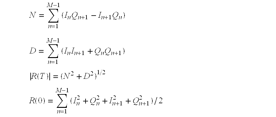
- the algorithm proceeds to compute the mean and variance of the clutter frequency over the FFT packet (step 34 ).
- Different methods for estimating the mean may be used including computing the first moment of the FFT spectrum of the packet, and counting zero-crossings.
- the preferred method is, however, the standard Kasai estimator which is both accurate and computationally efficient—the same reasons it is also commonly used in color flow imaging systems.
- the Kasai estimates for the mean and variance of the frequency of the I/Q data are defined by
- R ⁇ ( T ) ⁇ ( N 2 + D 2 ) 1 / 2
- T is the sampling period of the I/Q data.
- the estimated mean and variance of the clutter frequency are then fed into the filter selection logic 36 , which selects the most suitable filter cutoff for the current clutter signal from the LUT 22 .
- the high-pass filter cutoff may be based on the absolute value of the mean frequency, plus, e.g., 3 times the standard deviation.
- some persistence function (incorporated in the selection logic) may be applied to the prescribed wall filter cutoff frequency by, for example, averaging the cutoff frequency estimates over the last several FFT packets.
Landscapes
- Physics & Mathematics (AREA)
- Engineering & Computer Science (AREA)
- Radar, Positioning & Navigation (AREA)
- Remote Sensing (AREA)
- Acoustics & Sound (AREA)
- Computer Networks & Wireless Communication (AREA)
- General Physics & Mathematics (AREA)
- Ultra Sonic Daignosis Equipment (AREA)
- Measurement Of Velocity Or Position Using Acoustic Or Ultrasonic Waves (AREA)
Abstract
Description
Claims (21)
Priority Applications (6)
| Application Number | Priority Date | Filing Date | Title |
|---|---|---|---|
| US09/349,586 US6296612B1 (en) | 1999-07-09 | 1999-07-09 | Method and apparatus for adaptive wall filtering in spectral Doppler ultrasound imaging |
| IL13710900A IL137109A0 (en) | 1999-07-09 | 2000-06-30 | Method and apparatus for adaptive wall filtering in spectral doppler ultrasound imaging |
| JP2000204438A JP2001137243A (en) | 1999-07-09 | 2000-07-06 | Method and apparatus for adaptive wall filtering process in spectrum doppler ultrasonic imaging |
| DE60026239T DE60026239T2 (en) | 1999-07-09 | 2000-07-07 | Method and arrangement for spectral Doppler imaging with adaptive time domain wall filter |
| EP00305770A EP1067400B1 (en) | 1999-07-09 | 2000-07-07 | Method and apparatus for adaptive wall filtering in spectral Doppler ultrasound imaging |
| US09/656,481 US6390983B1 (en) | 1999-07-09 | 2000-09-07 | Method and apparatus for automatic muting of Doppler noise induced by ultrasound probe motion |
Applications Claiming Priority (1)
| Application Number | Priority Date | Filing Date | Title |
|---|---|---|---|
| US09/349,586 US6296612B1 (en) | 1999-07-09 | 1999-07-09 | Method and apparatus for adaptive wall filtering in spectral Doppler ultrasound imaging |
Related Child Applications (1)
| Application Number | Title | Priority Date | Filing Date |
|---|---|---|---|
| US09/656,481 Continuation-In-Part US6390983B1 (en) | 1999-07-09 | 2000-09-07 | Method and apparatus for automatic muting of Doppler noise induced by ultrasound probe motion |
Publications (1)
| Publication Number | Publication Date |
|---|---|
| US6296612B1 true US6296612B1 (en) | 2001-10-02 |
Family
ID=23373061
Family Applications (2)
| Application Number | Title | Priority Date | Filing Date |
|---|---|---|---|
| US09/349,586 Expired - Fee Related US6296612B1 (en) | 1999-07-09 | 1999-07-09 | Method and apparatus for adaptive wall filtering in spectral Doppler ultrasound imaging |
| US09/656,481 Expired - Fee Related US6390983B1 (en) | 1999-07-09 | 2000-09-07 | Method and apparatus for automatic muting of Doppler noise induced by ultrasound probe motion |
Family Applications After (1)
| Application Number | Title | Priority Date | Filing Date |
|---|---|---|---|
| US09/656,481 Expired - Fee Related US6390983B1 (en) | 1999-07-09 | 2000-09-07 | Method and apparatus for automatic muting of Doppler noise induced by ultrasound probe motion |
Country Status (5)
| Country | Link |
|---|---|
| US (2) | US6296612B1 (en) |
| EP (1) | EP1067400B1 (en) |
| JP (1) | JP2001137243A (en) |
| DE (1) | DE60026239T2 (en) |
| IL (1) | IL137109A0 (en) |
Cited By (50)
| Publication number | Priority date | Publication date | Assignee | Title |
|---|---|---|---|---|
| US6663566B2 (en) * | 2002-02-19 | 2003-12-16 | Ge Medical Systems Global Technology Company, Llc | Method and apparatus for automatic control of spectral doppler imaging |
| US20040037229A1 (en) * | 2002-08-21 | 2004-02-26 | D'souza Scott | Detection of denial-of-service attacks using frequency domain analysis |
| US20040050166A1 (en) * | 2002-09-16 | 2004-03-18 | Batzinger Thomas James | Phased array ultrasonic inspection method for industrial applications |
| US6792808B1 (en) | 2003-04-30 | 2004-09-21 | General Electric Company | Ultrasonic inspection method |
| US20040199078A1 (en) * | 1999-08-20 | 2004-10-07 | Mo Larry Y. L. | System and method for adaptive clutter filtering in ultrasound color flow imaging |
| US20050054931A1 (en) * | 2003-09-09 | 2005-03-10 | Clark David W. | Tracking clutter filter for spectral & audio doppler |
| US20050080329A1 (en) * | 2003-07-29 | 2005-04-14 | Kabushiki Kaisha Toshiba | Ultrasound doppler diagnostic apparatus and image date generating method |
| US6894640B1 (en) * | 2002-05-13 | 2005-05-17 | Honeywell International Inc. | Methods and apparatus for conversion of radar return data |
| US20050131300A1 (en) * | 2003-12-15 | 2005-06-16 | Siemens Medical Solutions Usa, Inc. | Automatic optimization for ultrasound medical imaging |
| US20050251034A1 (en) * | 2004-05-06 | 2005-11-10 | David Dubberstein | Data dependent color wall filters |
| US20050251008A1 (en) * | 2004-04-26 | 2005-11-10 | Lihong Pan | System and method for filtering in imaging systems |
| US20060098853A1 (en) * | 2002-12-02 | 2006-05-11 | Roundhill David N | Segmentation tool for identifying flow regions in an image system |
| US20080059098A1 (en) * | 2006-09-05 | 2008-03-06 | Yu Zhang | Method and apparatus for suppressing noise in a doppler system |
| US20090209861A1 (en) * | 2005-02-17 | 2009-08-20 | Panasonic Corporation | Ultrasonic Doppler Blood Flow Meter |
| US20110137174A1 (en) * | 2009-12-02 | 2011-06-09 | Medison Co., Ltd. | Ultrasound color doppler imaging system and method for filtering clutter signal of the same |
| US8226561B2 (en) | 1999-08-20 | 2012-07-24 | Zonare Medical Systems, Inc. | Ultrasound imaging system |
| US8780968B1 (en) * | 2013-03-15 | 2014-07-15 | DGS Global Systems, Inc. | Systems, methods, and devices for electronic spectrum management |
| US8787836B1 (en) | 2013-03-15 | 2014-07-22 | DGS Global Systems, Inc. | Systems, methods, and devices having databases and automated reports for electronic spectrum management |
| US8798548B1 (en) | 2013-03-15 | 2014-08-05 | DGS Global Systems, Inc. | Systems, methods, and devices having databases for electronic spectrum management |
| US8805292B1 (en) | 2013-03-15 | 2014-08-12 | DGS Global Systems, Inc. | Systems, methods, and devices for electronic spectrum management for identifying signal-emitting devices |
| US8873422B2 (en) | 2013-03-15 | 2014-10-28 | DGS Global Systems, Inc. | Systems, methods, and devices for electronic spectrum management for identifying open space |
| US8977212B2 (en) | 2013-03-15 | 2015-03-10 | DGS Global Systems, Inc. | Systems, methods, and devices for electronic spectrum management with remote access to data in a virtual computing network |
| US9537586B2 (en) | 2013-03-15 | 2017-01-03 | DGS Global Systems, Inc. | Systems, methods, and devices for electronic spectrum management with remote access to data in a virtual computing network |
| US9629613B2 (en) | 2012-10-30 | 2017-04-25 | Samsung Electronics Co., Ltd. | Method of determining beamforming coefficient, beamforming method and ultrasonic imaging apparatus |
| US10122479B2 (en) | 2017-01-23 | 2018-11-06 | DGS Global Systems, Inc. | Systems, methods, and devices for automatic signal detection with temporal feature extraction within a spectrum |
| US10219163B2 (en) | 2013-03-15 | 2019-02-26 | DGS Global Systems, Inc. | Systems, methods, and devices for electronic spectrum management |
| US10231206B2 (en) | 2013-03-15 | 2019-03-12 | DGS Global Systems, Inc. | Systems, methods, and devices for electronic spectrum management for identifying signal-emitting devices |
| US10237770B2 (en) | 2013-03-15 | 2019-03-19 | DGS Global Systems, Inc. | Systems, methods, and devices having databases and automated reports for electronic spectrum management |
| US10244504B2 (en) | 2013-03-15 | 2019-03-26 | DGS Global Systems, Inc. | Systems, methods, and devices for geolocation with deployable large scale arrays |
| US10257727B2 (en) | 2013-03-15 | 2019-04-09 | DGS Global Systems, Inc. | Systems methods, and devices having databases and automated reports for electronic spectrum management |
| US10257729B2 (en) | 2013-03-15 | 2019-04-09 | DGS Global Systems, Inc. | Systems, methods, and devices having databases for electronic spectrum management |
| US10257728B2 (en) | 2013-03-15 | 2019-04-09 | DGS Global Systems, Inc. | Systems, methods, and devices for electronic spectrum management |
| US10271233B2 (en) | 2013-03-15 | 2019-04-23 | DGS Global Systems, Inc. | Systems, methods, and devices for automatic signal detection with temporal feature extraction within a spectrum |
| US10299149B2 (en) | 2013-03-15 | 2019-05-21 | DGS Global Systems, Inc. | Systems, methods, and devices for electronic spectrum management |
| US10310534B2 (en) | 2012-07-31 | 2019-06-04 | Causam Energy, Inc. | System, method, and data packets for messaging for electric power grid elements over a secure internet protocol network |
| CN110353727A (en) * | 2019-06-03 | 2019-10-22 | 浙江聚康生物工程有限公司 | Wireless hand-held color-image forming apparatus and imaging method |
| US10459020B2 (en) | 2017-01-23 | 2019-10-29 | DGS Global Systems, Inc. | Systems, methods, and devices for automatic signal detection based on power distribution by frequency over time within a spectrum |
| US10497073B2 (en) | 2012-10-24 | 2019-12-03 | Causam Energy, Inc. | System, method, and apparatus for settlement for participation in an electric power grid |
| US10498951B2 (en) | 2017-01-23 | 2019-12-03 | Digital Global Systems, Inc. | Systems, methods, and devices for unmanned vehicle detection |
| US10523050B2 (en) | 2012-07-31 | 2019-12-31 | Causam Energy, Inc. | System, method, and apparatus for electric power grid and network management of grid elements |
| US10529241B2 (en) | 2017-01-23 | 2020-01-07 | Digital Global Systems, Inc. | Unmanned vehicle recognition and threat management |
| US10644815B2 (en) | 2017-01-23 | 2020-05-05 | Digital Global Systems, Inc. | Systems, methods, and devices for automatic signal detection based on power distribution by frequency over time within an electromagnetic spectrum |
| CN111388011A (en) * | 2020-03-26 | 2020-07-10 | 深圳开立生物医疗科技股份有限公司 | Ultrasonic Doppler blood flow imaging method, device, equipment and readable storage medium |
| CN111388010A (en) * | 2020-03-26 | 2020-07-10 | 深圳开立生物医疗科技股份有限公司 | Ultrasonic Doppler blood flow imaging method, device, equipment and readable storage medium |
| US10861112B2 (en) | 2012-07-31 | 2020-12-08 | Causam Energy, Inc. | Systems and methods for advanced energy settlements, network-based messaging, and applications supporting the same on a blockchain platform |
| US10943461B2 (en) | 2018-08-24 | 2021-03-09 | Digital Global Systems, Inc. | Systems, methods, and devices for automatic signal detection based on power distribution by frequency over time |
| US11004160B2 (en) | 2015-09-23 | 2021-05-11 | Causam Enterprises, Inc. | Systems and methods for advanced energy network |
| US20210137501A1 (en) * | 2019-10-04 | 2021-05-13 | Canon Medical Systems Corporation | Ultrasound diagnostic apparatus and examination method |
| US11646918B2 (en) | 2013-03-15 | 2023-05-09 | Digital Global Systems, Inc. | Systems, methods, and devices for electronic spectrum management for identifying open space |
| US12028729B2 (en) | 2023-05-24 | 2024-07-02 | Digital Global Systems, Inc. | Systems, methods, and devices having databases for electronic spectrum management |
Families Citing this family (34)
| Publication number | Priority date | Publication date | Assignee | Title |
|---|---|---|---|---|
| GB0030449D0 (en) * | 2000-12-13 | 2001-01-24 | Deltex Guernsey Ltd | Improvements in or relating to doppler haemodynamic monitors |
| US6689064B2 (en) * | 2001-06-22 | 2004-02-10 | Koninklijke Philips Electronics N.V. | Ultrasound clutter filter |
| WO2004109330A1 (en) * | 2003-06-10 | 2004-12-16 | Koninklijke Philips Electronics, N.V. | User interface for a three-dimensional colour ultrasound imaging system |
| US7395292B2 (en) * | 2003-10-08 | 2008-07-01 | Johnson Mark W | Method for displaying spectral trends in complex signals |
| US7627386B2 (en) * | 2004-10-07 | 2009-12-01 | Zonaire Medical Systems, Inc. | Ultrasound imaging system parameter optimization via fuzzy logic |
| US8002705B1 (en) | 2005-07-22 | 2011-08-23 | Zonaire Medical Systems, Inc. | Continuous transmit focusing method and apparatus for ultrasound imaging system |
| US8784318B1 (en) | 2005-07-22 | 2014-07-22 | Zonare Medical Systems, Inc. | Aberration correction using channel data in ultrasound imaging system |
| US8036856B2 (en) * | 2005-12-01 | 2011-10-11 | General Electric Company | Method and apparatus for automatically adjusting spectral doppler gain |
| US20080146922A1 (en) * | 2006-10-24 | 2008-06-19 | Zonare Medical Systems, Inc. | Control of user interfaces and displays for portable ultrasound unit and docking station |
| US8013538B2 (en) | 2007-01-26 | 2011-09-06 | Integrated Illumination Systems, Inc. | TRI-light |
| JP5247066B2 (en) * | 2007-06-04 | 2013-07-24 | 三菱電機株式会社 | Target tracking device |
| JP5214920B2 (en) * | 2007-07-24 | 2013-06-19 | 株式会社東芝 | Ultrasonic diagnostic apparatus and acoustic output method of ultrasonic diagnostic apparatus |
| CN101416885B (en) * | 2007-10-22 | 2012-10-17 | 深圳迈瑞生物医疗电子股份有限公司 | Frame equilibration circuit for ultrasonic imaging system |
| US20090112096A1 (en) * | 2007-10-29 | 2009-04-30 | Aloka Co., Ltd. | Methods and apparatus for ultrasound imaging |
| US9060669B1 (en) | 2007-12-20 | 2015-06-23 | Zonare Medical Systems, Inc. | System and method for providing variable ultrasound array processing in a post-storage mode |
| KR101055581B1 (en) * | 2008-03-20 | 2011-08-23 | 삼성메디슨 주식회사 | How to set filters for ultrasonic system and clutter rejection |
| US8255487B2 (en) | 2008-05-16 | 2012-08-28 | Integrated Illumination Systems, Inc. | Systems and methods for communicating in a lighting network |
| KR101100551B1 (en) | 2008-12-17 | 2011-12-29 | 삼성메디슨 주식회사 | Ultrasound system and method for filtering clutter signal |
| KR101120791B1 (en) * | 2009-11-16 | 2012-03-22 | 삼성메디슨 주식회사 | Ultrasound system and method for performing adaptive clutter filtering |
| CN102121991B (en) * | 2010-01-08 | 2013-01-23 | 郑州威科姆科技股份有限公司 | Interference suppression method and device based on BeiDou-I satellite signal reception |
| KR101239809B1 (en) * | 2010-05-07 | 2013-03-06 | 삼성메디슨 주식회사 | Ultrasound imaging device and method for clutter filtering |
| KR101232796B1 (en) * | 2010-07-22 | 2013-02-13 | 삼성메디슨 주식회사 | Ultrasound imaging device and method for clutter filtering |
| KR101339683B1 (en) | 2012-01-17 | 2013-12-10 | 서강대학교산학협력단 | Adaptive dynamic quadrature demodulation apparatus for ultrasound harmonic imaging and demodulation method thereof |
| US20140336510A1 (en) * | 2013-05-08 | 2014-11-13 | Siemens Medical Solutions Usa, Inc. | Enhancement in Diagnostic Ultrasound Spectral Doppler Imaging |
| JP6413616B2 (en) * | 2013-11-06 | 2018-10-31 | コニカミノルタ株式会社 | Ultrasonic diagnostic apparatus, controller for ultrasonic diagnostic apparatus, and control method for ultrasonic diagnostic apparatus |
| WO2016153098A1 (en) * | 2015-03-26 | 2016-09-29 | 알피니언메디칼시스템 주식회사 | Method and device for improving estimation quality of signal |
| CN105738887B (en) * | 2016-01-29 | 2018-03-06 | 西安电子科技大学 | The optimization method of airborne radar clutter power spectrum based on the division of Doppler's passage |
| KR102577752B1 (en) * | 2016-02-02 | 2023-09-12 | 삼성메디슨 주식회사 | Method of outputting a velocity of object and ultrasound apparatus thereof |
| EP3323350A3 (en) * | 2016-11-16 | 2018-06-20 | Huntleigh Technology Limited | Ultrasound doppler monitoring system |
| US11076835B2 (en) * | 2018-04-30 | 2021-08-03 | Bk Medical, Aps | Model-based control of a dynamic range of an ultrasound image |
| JP6483910B1 (en) * | 2018-11-28 | 2019-03-13 | メロディ・インターナショナル株式会社 | Ultrasonic inspection equipment |
| CN110907930B (en) * | 2019-11-29 | 2021-09-03 | 成都纳雷科技有限公司 | Vehicle-mounted radar target detection and estimation method and device based on angle estimation |
| WO2021257891A1 (en) * | 2020-06-19 | 2021-12-23 | EchoNous, Inc. | Device and methods for motion artifact suppression in auscultation and ultrasound data |
| CN112039453A (en) * | 2020-08-04 | 2020-12-04 | 中电科仪器仪表有限公司 | Automatic level control circuit for low-frequency signal |
Citations (7)
| Publication number | Priority date | Publication date | Assignee | Title |
|---|---|---|---|---|
| US5269308A (en) * | 1991-07-25 | 1993-12-14 | Matsushita Electric Industrial Co., Ltd. | Ultrasonic doppler imaging apparatus |
| US5299174A (en) * | 1992-04-10 | 1994-03-29 | Diasonics, Inc. | Automatic clutter elimination |
| US5383464A (en) * | 1991-07-02 | 1995-01-24 | Fujitsu Limited | Ultrasonic doppler diagnostic system |
| US5443071A (en) * | 1994-10-11 | 1995-08-22 | Siemens Medical Systems, Inc. | Quantitative color flow |
| US5544659A (en) * | 1994-12-29 | 1996-08-13 | Siemens Medical Systems, Inc. | Ultrasonic doppler imager having a reduced hardware adaptive tissue rejection filter arrangement |
| US5910118A (en) * | 1996-10-01 | 1999-06-08 | Kabushiki Kaisha Toshiba | Removal of clutter components in ultrasound color-doppler imaging |
| US6146331A (en) * | 1998-09-30 | 2000-11-14 | Siemens Medical Systems, Inc. | Method for improved clutter suppression for ultrasonic color doppler imaging |
Family Cites Families (5)
| Publication number | Priority date | Publication date | Assignee | Title |
|---|---|---|---|---|
| US5287753A (en) * | 1992-05-02 | 1994-02-22 | Advanced Technology Laboratories, Inc. | Continuous display of peak and mean blood flow velocities |
| US5349524A (en) * | 1993-01-08 | 1994-09-20 | General Electric Company | Color flow imaging system utilizing a time domain adaptive wall filter |
| US5524629A (en) * | 1994-11-02 | 1996-06-11 | General Electric Company | Color flow processor having adaptive wall filter |
| US5494037A (en) * | 1994-12-29 | 1996-02-27 | Siemens Medical Systems, Inc. | Ultrasonic doppler imager having a spatially smoothed control signal for an adaptive tissue rejection filter |
| US5827969A (en) * | 1996-06-12 | 1998-10-27 | Medasonics, Inc. | Portable hand held doppler fetal heart rate probe with selective power settings |
-
1999
- 1999-07-09 US US09/349,586 patent/US6296612B1/en not_active Expired - Fee Related
-
2000
- 2000-06-30 IL IL13710900A patent/IL137109A0/en unknown
- 2000-07-06 JP JP2000204438A patent/JP2001137243A/en not_active Withdrawn
- 2000-07-07 DE DE60026239T patent/DE60026239T2/en not_active Expired - Fee Related
- 2000-07-07 EP EP00305770A patent/EP1067400B1/en not_active Expired - Lifetime
- 2000-09-07 US US09/656,481 patent/US6390983B1/en not_active Expired - Fee Related
Patent Citations (7)
| Publication number | Priority date | Publication date | Assignee | Title |
|---|---|---|---|---|
| US5383464A (en) * | 1991-07-02 | 1995-01-24 | Fujitsu Limited | Ultrasonic doppler diagnostic system |
| US5269308A (en) * | 1991-07-25 | 1993-12-14 | Matsushita Electric Industrial Co., Ltd. | Ultrasonic doppler imaging apparatus |
| US5299174A (en) * | 1992-04-10 | 1994-03-29 | Diasonics, Inc. | Automatic clutter elimination |
| US5443071A (en) * | 1994-10-11 | 1995-08-22 | Siemens Medical Systems, Inc. | Quantitative color flow |
| US5544659A (en) * | 1994-12-29 | 1996-08-13 | Siemens Medical Systems, Inc. | Ultrasonic doppler imager having a reduced hardware adaptive tissue rejection filter arrangement |
| US5910118A (en) * | 1996-10-01 | 1999-06-08 | Kabushiki Kaisha Toshiba | Removal of clutter components in ultrasound color-doppler imaging |
| US6146331A (en) * | 1998-09-30 | 2000-11-14 | Siemens Medical Systems, Inc. | Method for improved clutter suppression for ultrasonic color doppler imaging |
Cited By (191)
| Publication number | Priority date | Publication date | Assignee | Title |
|---|---|---|---|---|
| US6997876B2 (en) * | 1999-08-20 | 2006-02-14 | Zonare Medical Systems, Inc. | Ultrasound clutter filtering with iterative high pass filter selection |
| US20040199078A1 (en) * | 1999-08-20 | 2004-10-07 | Mo Larry Y. L. | System and method for adaptive clutter filtering in ultrasound color flow imaging |
| US8764661B2 (en) | 1999-08-20 | 2014-07-01 | Zonare Medical Systems, Inc. | Echolocation data generation |
| US8679018B2 (en) | 1999-08-20 | 2014-03-25 | Zonare Medical Systems, Inc. | Broad-beam imaging |
| US8226561B2 (en) | 1999-08-20 | 2012-07-24 | Zonare Medical Systems, Inc. | Ultrasound imaging system |
| US20060100520A1 (en) * | 1999-08-20 | 2006-05-11 | Mo Larry Y L | Ultrasound system with iterative high pass filter selection |
| US6663566B2 (en) * | 2002-02-19 | 2003-12-16 | Ge Medical Systems Global Technology Company, Llc | Method and apparatus for automatic control of spectral doppler imaging |
| US6894640B1 (en) * | 2002-05-13 | 2005-05-17 | Honeywell International Inc. | Methods and apparatus for conversion of radar return data |
| US20040037229A1 (en) * | 2002-08-21 | 2004-02-26 | D'souza Scott | Detection of denial-of-service attacks using frequency domain analysis |
| US7283461B2 (en) * | 2002-08-21 | 2007-10-16 | Alcatel Canada Inc. | Detection of denial-of-service attacks using frequency domain analysis |
| US20040050166A1 (en) * | 2002-09-16 | 2004-03-18 | Batzinger Thomas James | Phased array ultrasonic inspection method for industrial applications |
| US6789427B2 (en) | 2002-09-16 | 2004-09-14 | General Electric Company | Phased array ultrasonic inspection method for industrial applications |
| US20060098853A1 (en) * | 2002-12-02 | 2006-05-11 | Roundhill David N | Segmentation tool for identifying flow regions in an image system |
| US8094893B2 (en) * | 2002-12-02 | 2012-01-10 | Koninklijke Philips Electronics N.V. | Segmentation tool for identifying flow regions in an image system |
| US6792808B1 (en) | 2003-04-30 | 2004-09-21 | General Electric Company | Ultrasonic inspection method |
| US7666142B2 (en) * | 2003-07-29 | 2010-02-23 | Kabushiki Kaisha Toshiba | Ultrasound doppler diagnostic apparatus and image data generating method |
| US20050080329A1 (en) * | 2003-07-29 | 2005-04-14 | Kabushiki Kaisha Toshiba | Ultrasound doppler diagnostic apparatus and image date generating method |
| US20050054931A1 (en) * | 2003-09-09 | 2005-03-10 | Clark David W. | Tracking clutter filter for spectral & audio doppler |
| US7288068B2 (en) * | 2003-12-15 | 2007-10-30 | Siemens Medical Solutions Usa, Inc. | Automatic optimization for ultrasound medical imaging |
| US20050131300A1 (en) * | 2003-12-15 | 2005-06-16 | Siemens Medical Solutions Usa, Inc. | Automatic optimization for ultrasound medical imaging |
| US7749166B2 (en) | 2004-04-26 | 2010-07-06 | General Electric Company | System and method for filtering in imaging systems |
| US20050251008A1 (en) * | 2004-04-26 | 2005-11-10 | Lihong Pan | System and method for filtering in imaging systems |
| US20050251034A1 (en) * | 2004-05-06 | 2005-11-10 | David Dubberstein | Data dependent color wall filters |
| US7118532B2 (en) * | 2004-05-06 | 2006-10-10 | General Electric Company | Data dependent color wall filters |
| US20090209861A1 (en) * | 2005-02-17 | 2009-08-20 | Panasonic Corporation | Ultrasonic Doppler Blood Flow Meter |
| US20080059098A1 (en) * | 2006-09-05 | 2008-03-06 | Yu Zhang | Method and apparatus for suppressing noise in a doppler system |
| US7421377B2 (en) * | 2006-09-05 | 2008-09-02 | Shenzhen Mindray Bio-Medical Electronics Co., Ltd. | Method and apparatus for supressing noise in a doppler system |
| CN101138507B (en) * | 2006-09-05 | 2010-05-12 | 深圳迈瑞生物医疗电子股份有限公司 | Doppler bloodstream aural signal processing method and device thereof |
| US20110137174A1 (en) * | 2009-12-02 | 2011-06-09 | Medison Co., Ltd. | Ultrasound color doppler imaging system and method for filtering clutter signal of the same |
| US8758250B2 (en) | 2009-12-02 | 2014-06-24 | Samsung Medison Co., Ltd. | Ultrasound color Doppler imaging system and method for filtering clutter signal of the same |
| US12013711B2 (en) | 2012-07-31 | 2024-06-18 | Causam Enterprises, Inc. | System, method, and data packets for messaging for electric power grid elements over a secure internet protocol network |
| US11774996B2 (en) | 2012-07-31 | 2023-10-03 | Causam Enterprises, Inc. | System, method, and apparatus for electric power grid and network management of grid elements |
| US10310534B2 (en) | 2012-07-31 | 2019-06-04 | Causam Energy, Inc. | System, method, and data packets for messaging for electric power grid elements over a secure internet protocol network |
| US10523050B2 (en) | 2012-07-31 | 2019-12-31 | Causam Energy, Inc. | System, method, and apparatus for electric power grid and network management of grid elements |
| US10998764B2 (en) | 2012-07-31 | 2021-05-04 | Causam Enterprises, Inc. | System, method, and apparatus for electric power grid and network management of grid elements |
| US10852760B2 (en) | 2012-07-31 | 2020-12-01 | Causam Enterprises, Inc. | System, method, and data packets for messaging for electric power grid elements over a secure internet protocol network |
| US11782471B2 (en) | 2012-07-31 | 2023-10-10 | Causam Enterprises, Inc. | System, method, and data packets for messaging for electric power grid elements over a secure internet protocol network |
| US12007802B2 (en) | 2012-07-31 | 2024-06-11 | Causam Enterprises, Inc. | System, method, and apparatus for electric power grid and network management of grid elements |
| US11747849B2 (en) | 2012-07-31 | 2023-09-05 | Causam Enterprises, Inc. | System, method, and apparatus for electric power grid and network management of grid elements |
| US11681317B2 (en) | 2012-07-31 | 2023-06-20 | Causam Enterprises, Inc. | System, method, and data packets for messaging for electric power grid elements over a secure internet protocol network |
| US11650613B2 (en) | 2012-07-31 | 2023-05-16 | Causam Enterprises, Inc. | System, method, and apparatus for electric power grid and network management of grid elements |
| US11501389B2 (en) | 2012-07-31 | 2022-11-15 | Causam Enterprises, Inc. | Systems and methods for advanced energy settlements, network-based messaging, and applications supporting the same on a blockchain platform |
| US11307602B2 (en) | 2012-07-31 | 2022-04-19 | Causam Enterprises, Inc. | System, method, and data packets for messaging for electric power grid elements over a secure internet protocol network |
| US10861112B2 (en) | 2012-07-31 | 2020-12-08 | Causam Energy, Inc. | Systems and methods for advanced energy settlements, network-based messaging, and applications supporting the same on a blockchain platform |
| US10985609B2 (en) | 2012-07-31 | 2021-04-20 | Causam Enterprises, Inc. | System, method, and apparatus for electric power grid and network management of grid elements |
| US11798103B2 (en) | 2012-10-24 | 2023-10-24 | Causam Exchange, Inc. | System, method, and apparatus for settlement for participation in an electric power grid |
| US11195239B2 (en) | 2012-10-24 | 2021-12-07 | Causam Enterprises, Inc. | System, method, and apparatus for settlement for participation in an electric power grid |
| US11263710B2 (en) | 2012-10-24 | 2022-03-01 | Causam Exchange, Inc. | System, method, and apparatus for settlement for participation in an electric power grid |
| US11270392B2 (en) | 2012-10-24 | 2022-03-08 | Causam Exchange, Inc. | System, method, and apparatus for settlement for participation in an electric power grid |
| US11288755B2 (en) | 2012-10-24 | 2022-03-29 | Causam Exchange, Inc. | System, method, and apparatus for settlement for participation in an electric power grid |
| US11803921B2 (en) | 2012-10-24 | 2023-10-31 | Causam Exchange, Inc. | System, method, and apparatus for settlement for participation in an electric power grid |
| US10529037B2 (en) | 2012-10-24 | 2020-01-07 | Causam Energy, Inc. | System, method, and apparatus for settlement for participation in an electric power grid |
| US10521868B2 (en) | 2012-10-24 | 2019-12-31 | Causam Energy, Inc. | System, method, and apparatus for settlement for participation in an electric power grid |
| US11816744B2 (en) | 2012-10-24 | 2023-11-14 | Causam Exchange, Inc. | System, method, and apparatus for settlement for participation in an electric power grid |
| US10497074B2 (en) | 2012-10-24 | 2019-12-03 | Causam Energy, Inc. | System, method, and apparatus for settlement for participation in an electric power grid |
| US10497073B2 (en) | 2012-10-24 | 2019-12-03 | Causam Energy, Inc. | System, method, and apparatus for settlement for participation in an electric power grid |
| US11823292B2 (en) | 2012-10-24 | 2023-11-21 | Causam Enterprises, Inc. | System, method, and apparatus for settlement for participation in an electric power grid |
| US9629613B2 (en) | 2012-10-30 | 2017-04-25 | Samsung Electronics Co., Ltd. | Method of determining beamforming coefficient, beamforming method and ultrasonic imaging apparatus |
| US10644912B2 (en) | 2013-03-15 | 2020-05-05 | Digital Global Systems, Inc. | Systems, methods, and devices for electronic spectrum management for identifying open space |
| US11259197B2 (en) | 2013-03-15 | 2022-02-22 | Digital Global Systems, Inc. | Systems, methods, and devices having databases and automated reports for electronic spectrum management |
| US9749069B2 (en) | 2013-03-15 | 2017-08-29 | DGS Global Systems, Inc. | Systems, methods, and devices for electronic spectrum management |
| US9985810B2 (en) | 2013-03-15 | 2018-05-29 | DGS Global Systems, Inc. | Systems, methods, and devices for electronic spectrum management for identifying open space |
| US8780968B1 (en) * | 2013-03-15 | 2014-07-15 | DGS Global Systems, Inc. | Systems, methods, and devices for electronic spectrum management |
| US10219163B2 (en) | 2013-03-15 | 2019-02-26 | DGS Global Systems, Inc. | Systems, methods, and devices for electronic spectrum management |
| US10231206B2 (en) | 2013-03-15 | 2019-03-12 | DGS Global Systems, Inc. | Systems, methods, and devices for electronic spectrum management for identifying signal-emitting devices |
| US10237770B2 (en) | 2013-03-15 | 2019-03-19 | DGS Global Systems, Inc. | Systems, methods, and devices having databases and automated reports for electronic spectrum management |
| US10237099B2 (en) | 2013-03-15 | 2019-03-19 | DGS Global Systems, Inc. | Systems, methods, and devices for electronic spectrum management for identifying open space |
| US10244504B2 (en) | 2013-03-15 | 2019-03-26 | DGS Global Systems, Inc. | Systems, methods, and devices for geolocation with deployable large scale arrays |
| US10257727B2 (en) | 2013-03-15 | 2019-04-09 | DGS Global Systems, Inc. | Systems methods, and devices having databases and automated reports for electronic spectrum management |
| US10257729B2 (en) | 2013-03-15 | 2019-04-09 | DGS Global Systems, Inc. | Systems, methods, and devices having databases for electronic spectrum management |
| US10257728B2 (en) | 2013-03-15 | 2019-04-09 | DGS Global Systems, Inc. | Systems, methods, and devices for electronic spectrum management |
| US10271233B2 (en) | 2013-03-15 | 2019-04-23 | DGS Global Systems, Inc. | Systems, methods, and devices for automatic signal detection with temporal feature extraction within a spectrum |
| US10284309B2 (en) | 2013-03-15 | 2019-05-07 | DGS Global Systems, Inc. | Systems, methods, and devices for electronic spectrum management |
| US10299149B2 (en) | 2013-03-15 | 2019-05-21 | DGS Global Systems, Inc. | Systems, methods, and devices for electronic spectrum management |
| US9622041B2 (en) | 2013-03-15 | 2017-04-11 | DGS Global Systems, Inc. | Systems, methods, and devices for electronic spectrum management |
| US8787836B1 (en) | 2013-03-15 | 2014-07-22 | DGS Global Systems, Inc. | Systems, methods, and devices having databases and automated reports for electronic spectrum management |
| US12003990B2 (en) | 2013-03-15 | 2024-06-04 | Digital Global Systems, Inc. | Systems, methods, and devices for electronic spectrum management |
| US10492091B2 (en) | 2013-03-15 | 2019-11-26 | DGS Global Systems, Inc. | Systems, methods, and devices having databases and automated reports for electronic spectrum management |
| US9537586B2 (en) | 2013-03-15 | 2017-01-03 | DGS Global Systems, Inc. | Systems, methods, and devices for electronic spectrum management with remote access to data in a virtual computing network |
| US11991547B2 (en) | 2013-03-15 | 2024-05-21 | Digital Global Systems, Inc. | Systems, methods, and devices for automatic signal detection with temporal feature extraction within a spectrum |
| US9420473B2 (en) | 2013-03-15 | 2016-08-16 | DGS Global Systems, Inc. | Systems, methods, and devices for electronic spectrum management |
| US10517005B2 (en) | 2013-03-15 | 2019-12-24 | Digital Global Systems, Inc. | Systems, methods, and devices for electronic spectrum management |
| US9414237B2 (en) | 2013-03-15 | 2016-08-09 | DGS Global Systems, Inc. | Systems, methods, and devices for electronic spectrum management |
| US9288683B2 (en) | 2013-03-15 | 2016-03-15 | DGS Global Systems, Inc. | Systems, methods, and devices for electronic spectrum management |
| US10531323B2 (en) | 2013-03-15 | 2020-01-07 | Digital Global Systems, Inc. | Systems, methods, and devices having databases and automated reports for electronic spectrum management |
| US9253673B2 (en) | 2013-03-15 | 2016-02-02 | DGS Global Systems, Inc. | Systems, methods, and devices having databases and automated reports for electronic spectrum management |
| US11985013B2 (en) | 2013-03-15 | 2024-05-14 | Digital Global Systems, Inc. | Systems, methods, and devices for electronic spectrum management for identifying open space |
| US10554317B2 (en) | 2013-03-15 | 2020-02-04 | Digital Global Systems, Inc. | Systems, methods, and devices for electronic spectrum management |
| US10555180B2 (en) | 2013-03-15 | 2020-02-04 | Digital Global Systems, Inc. | Systems, methods, and devices for electronic spectrum management |
| US10575274B2 (en) | 2013-03-15 | 2020-02-25 | Digital Global Systems, Inc. | Systems, methods, and devices for electronic spectrum management for identifying signal-emitting devices |
| US10582471B2 (en) | 2013-03-15 | 2020-03-03 | Digital Global Systems, Inc. | Systems, methods, and devices for geolocation with deployable large scale arrays |
| US10609586B2 (en) | 2013-03-15 | 2020-03-31 | Digital Global Systems, Inc. | Systems, methods, and devices having databases for electronic spectrum management |
| US10623976B2 (en) | 2013-03-15 | 2020-04-14 | Digital Global Systems, Inc. | Systems, methods, and devices for electronic spectrum management |
| US10645601B2 (en) | 2013-03-15 | 2020-05-05 | Digital Global Systems, Inc. | Systems, methods, and devices for automatic signal detection with temporal feature extraction within a spectrum |
| US9253648B2 (en) | 2013-03-15 | 2016-02-02 | DGS Global Systems, Inc. | Systems, methods, and devices for electronic spectrum management |
| US11974149B2 (en) | 2013-03-15 | 2024-04-30 | Digital Global Systems, Inc. | Systems, methods, and devices having databases and automated reports for electronic spectrum management |
| US10694413B2 (en) | 2013-03-15 | 2020-06-23 | Digital Global Systems, Inc. | Systems, methods, and devices having databases and automated reports for electronic spectrum management |
| US11943737B2 (en) | 2013-03-15 | 2024-03-26 | Digital Global Systems, Inc. | Systems, methods, and devices for electronic spectrum management for identifying signal-emitting devices |
| US11930382B2 (en) | 2013-03-15 | 2024-03-12 | Digital Global Systems, Inc. | Systems, methods, and devices having databases and automated reports for electronic spectrum management |
| US11901963B1 (en) | 2013-03-15 | 2024-02-13 | Digital Global Systems, Inc. | Systems and methods for analyzing signals of interest |
| US10797917B2 (en) | 2013-03-15 | 2020-10-06 | Digital Global Systems, Inc. | Systems, methods, and devices for electronic spectrum management for identifying open space |
| US11838154B2 (en) | 2013-03-15 | 2023-12-05 | Digital Global Systems, Inc. | Systems, methods, and devices for electronic spectrum management for identifying open space |
| US9191848B2 (en) | 2013-03-15 | 2015-11-17 | DGS Global Systems, Inc. | Systems, methods, and devices for electronic spectrum management for identifying signal-emitting devices |
| US11838780B2 (en) | 2013-03-15 | 2023-12-05 | Digital Global Systems, Inc. | Systems, methods, and devices for automatic signal detection with temporal feature extraction within a spectrum |
| US9185591B2 (en) | 2013-03-15 | 2015-11-10 | DGS Global Systems, Inc. | Systems, methods, and devices for electronic spectrum management with remote access to data in a virtual computing network |
| US8798548B1 (en) | 2013-03-15 | 2014-08-05 | DGS Global Systems, Inc. | Systems, methods, and devices having databases for electronic spectrum management |
| US10945146B2 (en) | 2013-03-15 | 2021-03-09 | Digital Global Systems, Inc. | Systems, methods, and devices having databases and automated reports for electronic spectrum management |
| US8805292B1 (en) | 2013-03-15 | 2014-08-12 | DGS Global Systems, Inc. | Systems, methods, and devices for electronic spectrum management for identifying signal-emitting devices |
| US10959204B2 (en) | 2013-03-15 | 2021-03-23 | Digital Global Systems, Inc. | Systems, methods, and devices for geolocation with deployable large scale arrays |
| US9094975B2 (en) | 2013-03-15 | 2015-07-28 | DGS Global Systems, Inc. | Systems, methods, and devices for electronic spectrum management |
| US10999752B2 (en) | 2013-03-15 | 2021-05-04 | Digital Global Systems, Inc. | Systems, methods, and devices for electronic spectrum management |
| US9094974B2 (en) | 2013-03-15 | 2015-07-28 | DGS Globals Systems, Inc. | Systems, methods, and devices for electronic spectrum management |
| US8805291B1 (en) | 2013-03-15 | 2014-08-12 | DGS Global Systems, Inc. | Systems, methods, and devices for electronic spectrum management |
| US8824536B1 (en) | 2013-03-15 | 2014-09-02 | DGS Global Systems, Inc. | Systems, methods, and devices for electronic spectrum management |
| US11076308B2 (en) | 2013-03-15 | 2021-07-27 | Digital Global Systems, Inc. | Systems, methods, and devices for electronic spectrum management |
| US11082870B2 (en) | 2013-03-15 | 2021-08-03 | Digital Global Systems, Inc. | Systems, methods, and devices for automatic signal detection with temporal feature extraction within a spectrum |
| US11082859B2 (en) | 2013-03-15 | 2021-08-03 | Digital Global Systems, Inc. | Systems, methods, and devices for electronic spectrum management |
| US11082869B2 (en) | 2013-03-15 | 2021-08-03 | Digital Global Systems, Inc. | Systems, methods, and devices having databases for electronic spectrum management |
| US11792762B1 (en) | 2013-03-15 | 2023-10-17 | Digital Global Systems, Inc. | Systems, methods, and devices for electronic spectrum management for identifying signal-emitting devices |
| US11140648B2 (en) | 2013-03-15 | 2021-10-05 | Digital Global Systems, Inc. | Systems, methods, and devices for electronic spectrum management for identifying signal-emitting devices |
| US11791913B2 (en) | 2013-03-15 | 2023-10-17 | Digital Global Systems, Inc. | Systems, methods, and devices for electronic spectrum management |
| US8868005B1 (en) | 2013-03-15 | 2014-10-21 | DGS Global Systems, Inc. | Systems, methods, and devices having databases for electronic spectrum management |
| US9078162B2 (en) | 2013-03-15 | 2015-07-07 | DGS Global Systems, Inc. | Systems, methods, and devices for electronic spectrum management |
| US11223431B2 (en) | 2013-03-15 | 2022-01-11 | Digital Global Systems, Inc. | Systems, methods, and devices for electronic spectrum management |
| US8868004B2 (en) | 2013-03-15 | 2014-10-21 | DGS Global Systems, Inc. | Systems, methods, and devices for electronic spectrum management |
| US11234146B2 (en) | 2013-03-15 | 2022-01-25 | Digital Global Systems, Inc. | Systems, methods, and devices having databases and automated reports for electronic spectrum management |
| US9635573B2 (en) | 2013-03-15 | 2017-04-25 | DGS Global Systems, Inc. | Systems, methods, and devices for electronic spectrum management for identifying open space |
| US9008587B2 (en) | 2013-03-15 | 2015-04-14 | DGS Digital Global Systems, Inc. | Systems, methods, and devices having databases for electronic spectrum management |
| US8977212B2 (en) | 2013-03-15 | 2015-03-10 | DGS Global Systems, Inc. | Systems, methods, and devices for electronic spectrum management with remote access to data in a virtual computing network |
| US8964824B2 (en) * | 2013-03-15 | 2015-02-24 | DGS Global Systems, Inc. | Systems, methods, and devices for electronic spectrum management |
| US8891401B1 (en) | 2013-03-15 | 2014-11-18 | DGS Global Systems, Inc. | Systems, methods, and devices for electronic spectrum management for identifying open space |
| US8873422B2 (en) | 2013-03-15 | 2014-10-28 | DGS Global Systems, Inc. | Systems, methods, and devices for electronic spectrum management for identifying open space |
| US11736952B2 (en) | 2013-03-15 | 2023-08-22 | Digital Global Systems, Inc. | Systems, methods, and devices for electronic spectrum management |
| US11463898B2 (en) | 2013-03-15 | 2022-10-04 | Digital Global Systems, Inc. | Systems, methods, and devices for electronic spectrum management |
| US11470572B2 (en) | 2013-03-15 | 2022-10-11 | Digital Global Systems, Inc. | Systems, methods, and devices for geolocation with deployable large scale arrays |
| US8886131B1 (en) | 2013-03-15 | 2014-11-11 | DGS Global Systems, Inc. | Systems, methods, and devices for electronic spectrum management for identifying signal-emitting devices |
| US11509512B2 (en) | 2013-03-15 | 2022-11-22 | Digital Global Systems, Inc. | Systems, methods, and devices for electronic spectrum management for identifying open space |
| US11706651B1 (en) | 2013-03-15 | 2023-07-18 | Digital Global Systems, Inc. | Systems, methods, and devices for automatic signal detection with temporal feature extraction within a spectrum |
| US8874044B1 (en) | 2013-03-15 | 2014-10-28 | DGS Global Systems, Inc. | Systems, methods, and devices having databases and automated reports for electronic spectrum management |
| US11558764B2 (en) | 2013-03-15 | 2023-01-17 | Digital Global Systems, Inc. | Systems, methods, and devices having databases for electronic spectrum management |
| US11588562B2 (en) | 2013-03-15 | 2023-02-21 | Digital Global Systems, Inc. | Systems, methods, and devices for electronic spectrum management |
| US11665565B2 (en) | 2013-03-15 | 2023-05-30 | Digital Global Systems, Inc. | Systems, methods, and devices having databases for electronic spectrum management |
| US11601833B2 (en) | 2013-03-15 | 2023-03-07 | Digital Global Systems, Inc. | Systems, methods, and devices for automatic signal detection with temporal feature extraction within a spectrum |
| US11617089B2 (en) | 2013-03-15 | 2023-03-28 | Digital Global Systems, Inc. | Systems, methods, and devices for electronic spectrum management |
| US11665664B2 (en) | 2013-03-15 | 2023-05-30 | Digital Global Systems, Inc. | Systems, methods, and devices for electronic spectrum management for identifying signal-emitting devices |
| US11637641B1 (en) | 2013-03-15 | 2023-04-25 | Digital Global Systems, Inc. | Systems, methods, and devices for electronic spectrum management |
| US11653236B2 (en) | 2013-03-15 | 2023-05-16 | Digital Global Systems, Inc. | Systems, methods, and devices for electronic spectrum management |
| US11647409B2 (en) | 2013-03-15 | 2023-05-09 | Digital Global Systems, Inc. | Systems, methods, and devices having databases and automated reports for electronic spectrum management |
| US11646918B2 (en) | 2013-03-15 | 2023-05-09 | Digital Global Systems, Inc. | Systems, methods, and devices for electronic spectrum management for identifying open space |
| US20140323055A1 (en) * | 2013-03-15 | 2014-10-30 | DGS Global Systems, Inc. | Systems, methods, and devices for electronic spectrum management |
| US11004160B2 (en) | 2015-09-23 | 2021-05-11 | Causam Enterprises, Inc. | Systems and methods for advanced energy network |
| US10859619B2 (en) | 2017-01-23 | 2020-12-08 | Digital Global Systems, Inc. | Systems, methods, and devices for automatic signal detection based on power distribution by frequency over time within a spectrum |
| US10498951B2 (en) | 2017-01-23 | 2019-12-03 | Digital Global Systems, Inc. | Systems, methods, and devices for unmanned vehicle detection |
| US11668739B2 (en) | 2017-01-23 | 2023-06-06 | Digital Global Systems, Inc. | Systems, methods, and devices for automatic signal detection based on power distribution by frequency over time within a spectrum |
| US10122479B2 (en) | 2017-01-23 | 2018-11-06 | DGS Global Systems, Inc. | Systems, methods, and devices for automatic signal detection with temporal feature extraction within a spectrum |
| US11549976B2 (en) | 2017-01-23 | 2023-01-10 | Digital Global Systems, Inc. | Systems, methods, and devices for automatic signal detection based on power distribution by frequency over time within a spectrum |
| US11521498B2 (en) | 2017-01-23 | 2022-12-06 | Digital Global Systems, Inc. | Unmanned vehicle recognition and threat management |
| US10459020B2 (en) | 2017-01-23 | 2019-10-29 | DGS Global Systems, Inc. | Systems, methods, and devices for automatic signal detection based on power distribution by frequency over time within a spectrum |
| US11645921B2 (en) | 2017-01-23 | 2023-05-09 | Digital Global Systems, Inc. | Unmanned vehicle recognition and threat management |
| US11750911B2 (en) | 2017-01-23 | 2023-09-05 | Digital Global Systems, Inc. | Systems, methods, and devices for unmanned vehicle detection |
| US11764883B2 (en) | 2017-01-23 | 2023-09-19 | Digital Global Systems, Inc. | Systems, methods, and devices for automatic signal detection based on power distribution by frequency over time within an electromagnetic spectrum |
| US11221357B2 (en) | 2017-01-23 | 2022-01-11 | Digital Global Systems, Inc. | Systems, methods, and devices for automatic signal detection based on power distribution by frequency over time within a spectrum |
| US11783712B1 (en) | 2017-01-23 | 2023-10-10 | Digital Global Systems, Inc. | Unmanned vehicle recognition and threat management |
| US10529241B2 (en) | 2017-01-23 | 2020-01-07 | Digital Global Systems, Inc. | Unmanned vehicle recognition and threat management |
| US11159256B2 (en) | 2017-01-23 | 2021-10-26 | Digital Global Systems, Inc. | Systems, methods, and devices for automatic signal detection based on power distribution by frequency over time within an electromagnetic spectrum |
| US11115585B2 (en) | 2017-01-23 | 2021-09-07 | Digital Global Systems, Inc. | Systems, methods, and devices for unmanned vehicle detection |
| US10644815B2 (en) | 2017-01-23 | 2020-05-05 | Digital Global Systems, Inc. | Systems, methods, and devices for automatic signal detection based on power distribution by frequency over time within an electromagnetic spectrum |
| US11622170B2 (en) | 2017-01-23 | 2023-04-04 | Digital Global Systems, Inc. | Systems, methods, and devices for unmanned vehicle detection |
| US10798297B2 (en) | 2017-01-23 | 2020-10-06 | Digital Global Systems, Inc. | Systems, methods, and devices for unmanned vehicle detection |
| US11328609B2 (en) | 2017-01-23 | 2022-05-10 | Digital Global Systems, Inc. | Unmanned vehicle recognition and threat management |
| US11965922B2 (en) | 2017-01-23 | 2024-04-23 | Digital Global Systems, Inc. | Systems, methods, and devices for automatic signal detection based on power distribution by frequency over time within a spectrum |
| US10943493B2 (en) | 2017-01-23 | 2021-03-09 | Digital Global Systems, Inc. | Unmanned vehicle recognition and threat management |
| US11860209B2 (en) | 2017-01-23 | 2024-01-02 | Digital Global Systems, Inc. | Systems, methods, and devices for automatic signal detection based on power distribution by frequency over time within a spectrum |
| US11871103B2 (en) | 2017-01-23 | 2024-01-09 | Digital Global Systems, Inc. | Systems, methods, and devices for unmanned vehicle detection |
| US11956025B2 (en) | 2017-01-23 | 2024-04-09 | Digital Global Systems, Inc. | Systems, methods, and devices for automatic signal detection based on power distribution by frequency over time within an electromagnetic spectrum |
| US11893893B1 (en) | 2017-01-23 | 2024-02-06 | Digital Global Systems, Inc. | Unmanned vehicle recognition and threat management |
| US10700794B2 (en) | 2017-01-23 | 2020-06-30 | Digital Global Systems, Inc. | Systems, methods, and devices for automatic signal detection based on power distribution by frequency over time within an electromagnetic spectrum |
| US10943461B2 (en) | 2018-08-24 | 2021-03-09 | Digital Global Systems, Inc. | Systems, methods, and devices for automatic signal detection based on power distribution by frequency over time |
| US11322011B2 (en) | 2018-08-24 | 2022-05-03 | Digital Global Systems, Inc. | Systems, methods, and devices for automatic signal detection based on power distribution by frequency over time |
| US11676472B2 (en) | 2018-08-24 | 2023-06-13 | Digital Global Systems, Inc. | Systems, methods, and devices for automatic signal detection based on power distribution by frequency over time |
| US11948446B1 (en) | 2018-08-24 | 2024-04-02 | Digital Global Systems, Inc. | Systems, methods, and devices for automatic signal detection based on power distribution by frequency over time |
| US11869330B2 (en) | 2018-08-24 | 2024-01-09 | Digital Global Systems, Inc. | Systems, methods, and devices for automatic signal detection based on power distribution by frequency over time |
| CN110353727B (en) * | 2019-06-03 | 2021-11-23 | 浙江聚康生物工程有限公司 | Wireless handheld color imaging device and imaging method |
| CN110353727A (en) * | 2019-06-03 | 2019-10-22 | 浙江聚康生物工程有限公司 | Wireless hand-held color-image forming apparatus and imaging method |
| US11896435B2 (en) * | 2019-10-04 | 2024-02-13 | Canon Medical Systems Corporation | Ultrasound diagnostic apparatus and examination method |
| US20210137501A1 (en) * | 2019-10-04 | 2021-05-13 | Canon Medical Systems Corporation | Ultrasound diagnostic apparatus and examination method |
| CN111388011A (en) * | 2020-03-26 | 2020-07-10 | 深圳开立生物医疗科技股份有限公司 | Ultrasonic Doppler blood flow imaging method, device, equipment and readable storage medium |
| CN111388011B (en) * | 2020-03-26 | 2023-02-21 | 深圳开立生物医疗科技股份有限公司 | Ultrasonic Doppler blood flow imaging method, device, equipment and readable storage medium |
| CN111388010A (en) * | 2020-03-26 | 2020-07-10 | 深圳开立生物医疗科技股份有限公司 | Ultrasonic Doppler blood flow imaging method, device, equipment and readable storage medium |
| US12028729B2 (en) | 2023-05-24 | 2024-07-02 | Digital Global Systems, Inc. | Systems, methods, and devices having databases for electronic spectrum management |
| US12028121B2 (en) | 2023-08-21 | 2024-07-02 | Digital Global Systems, Inc. | Systems, methods, and devices for electronic spectrum management |
Also Published As
| Publication number | Publication date |
|---|---|
| IL137109A0 (en) | 2001-06-14 |
| US6390983B1 (en) | 2002-05-21 |
| JP2001137243A (en) | 2001-05-22 |
| EP1067400A2 (en) | 2001-01-10 |
| EP1067400B1 (en) | 2006-03-01 |
| DE60026239T2 (en) | 2006-11-16 |
| DE60026239D1 (en) | 2006-04-27 |
| EP1067400A3 (en) | 2004-05-26 |
Similar Documents
| Publication | Publication Date | Title |
|---|---|---|
| US6296612B1 (en) | Method and apparatus for adaptive wall filtering in spectral Doppler ultrasound imaging | |
| US5935074A (en) | Method and apparatus for automatic tracing of Doppler time-velocity waveform envelope | |
| EP1016880B1 (en) | Automatic adjustment of velocity scale and pulse repetition frequency for doppler ultrasound spectrograms | |
| US6251077B1 (en) | Method and apparatus for dynamic noise reduction for doppler audio output | |
| US6663566B2 (en) | Method and apparatus for automatic control of spectral doppler imaging | |
| US6277075B1 (en) | Method and apparatus for visualization of motion in ultrasound flow imaging using continuous data acquisition | |
| US6126605A (en) | Ultrasound color flow display optimization by adjusting dynamic range | |
| JP4405017B2 (en) | Method and apparatus for automatic time and / or lateral gain compensation in B-mode ultrasound imaging | |
| US7611464B2 (en) | Method for processing Doppler signal gaps | |
| US5662115A (en) | Method for determining the velocity-time spectrum of blood flow | |
| US5170792A (en) | Adaptive tissue velocity compensation for ultrasonic Doppler imaging | |
| US5379770A (en) | Method and apparatus for transcranial doppler sonography | |
| US5445156A (en) | Method for adaptively filtering doppler signals using a complex time domain filter | |
| US6017309A (en) | Ultrasound color flow display optimization by adjusting color maps | |
| US5177691A (en) | Measuring velocity of a target by Doppler shift, using improvements in calculating discrete Fourier transform | |
| US6142943A (en) | Doppler ultrasound automatic spectrum optimization | |
| US6773403B2 (en) | Ultrasonic apparatus and method for measuring the velocities of human tissues using the doppler effects | |
| US6179781B1 (en) | Medical diagnostic ultrasound method and apparatus for improving doppler processing | |
| CN100531674C (en) | Ultrasonographic device | |
| EP1060410A1 (en) | Ultrasound color flow display optimization | |
| US5188112A (en) | Ultrasonic Doppler imaging systems with improved flow sensitivity | |
| EP1060406B1 (en) | Ultrasound color flow display optimization by adjustment of threshold using sampling | |
| JPH0716227A (en) | Ultrasonic pulse dopller diagnotic device | |
| JPH0763467B2 (en) | Ultrasonic Doppler blood flow meter |
Legal Events
| Date | Code | Title | Description |
|---|---|---|---|
| AS | Assignment |
Owner name: GENERAL ELECTRIC COMPANY, NEW YORK Free format text: ASSIGNMENT OF ASSIGNORS INTEREST;ASSIGNORS:MO, LARRY Y. L.;KULAKOWSKI, RICHARD M.;REEL/FRAME:010094/0986 Effective date: 19990702 |
|
| FEPP | Fee payment procedure |
Free format text: PAYOR NUMBER ASSIGNED (ORIGINAL EVENT CODE: ASPN); ENTITY STATUS OF PATENT OWNER: LARGE ENTITY |
|
| CC | Certificate of correction | ||
| FPAY | Fee payment |
Year of fee payment: 4 |
|
| FEPP | Fee payment procedure |
Free format text: PAYER NUMBER DE-ASSIGNED (ORIGINAL EVENT CODE: RMPN); ENTITY STATUS OF PATENT OWNER: LARGE ENTITY Free format text: PAYOR NUMBER ASSIGNED (ORIGINAL EVENT CODE: ASPN); ENTITY STATUS OF PATENT OWNER: LARGE ENTITY |
|
| FPAY | Fee payment |
Year of fee payment: 8 |
|
| REMI | Maintenance fee reminder mailed | ||
| LAPS | Lapse for failure to pay maintenance fees | ||
| STCH | Information on status: patent discontinuation |
Free format text: PATENT EXPIRED DUE TO NONPAYMENT OF MAINTENANCE FEES UNDER 37 CFR 1.362 |
|
| FP | Lapsed due to failure to pay maintenance fee |
Effective date: 20131002 |