EP0344713B1 - Fahrzeuggetriebe, insbesondere für Ackerbauschlepper - Google Patents
Fahrzeuggetriebe, insbesondere für Ackerbauschlepper Download PDFInfo
- Publication number
- EP0344713B1 EP0344713B1 EP89109735A EP89109735A EP0344713B1 EP 0344713 B1 EP0344713 B1 EP 0344713B1 EP 89109735 A EP89109735 A EP 89109735A EP 89109735 A EP89109735 A EP 89109735A EP 0344713 B1 EP0344713 B1 EP 0344713B1
- Authority
- EP
- European Patent Office
- Prior art keywords
- transmission
- stage
- fact
- gears
- solenoid valves
- Prior art date
- Legal status (The legal status is an assumption and is not a legal conclusion. Google has not performed a legal analysis and makes no representation as to the accuracy of the status listed.)
- Expired - Lifetime
Links
Images

Classifications
-
- F—MECHANICAL ENGINEERING; LIGHTING; HEATING; WEAPONS; BLASTING
- F16—ENGINEERING ELEMENTS AND UNITS; GENERAL MEASURES FOR PRODUCING AND MAINTAINING EFFECTIVE FUNCTIONING OF MACHINES OR INSTALLATIONS; THERMAL INSULATION IN GENERAL
- F16H—GEARING
- F16H61/00—Control functions within control units of change-speed- or reversing-gearings for conveying rotary motion ; Control of exclusively fluid gearing, friction gearing, gearings with endless flexible members or other particular types of gearing
- F16H61/68—Control functions within control units of change-speed- or reversing-gearings for conveying rotary motion ; Control of exclusively fluid gearing, friction gearing, gearings with endless flexible members or other particular types of gearing specially adapted for stepped gearings
- F16H61/684—Control functions within control units of change-speed- or reversing-gearings for conveying rotary motion ; Control of exclusively fluid gearing, friction gearing, gearings with endless flexible members or other particular types of gearing specially adapted for stepped gearings without interruption of drive
- F16H61/688—Control functions within control units of change-speed- or reversing-gearings for conveying rotary motion ; Control of exclusively fluid gearing, friction gearing, gearings with endless flexible members or other particular types of gearing specially adapted for stepped gearings without interruption of drive with two inputs, e.g. selection of one of two torque-flow paths by clutches
-
- F—MECHANICAL ENGINEERING; LIGHTING; HEATING; WEAPONS; BLASTING
- F16—ENGINEERING ELEMENTS AND UNITS; GENERAL MEASURES FOR PRODUCING AND MAINTAINING EFFECTIVE FUNCTIONING OF MACHINES OR INSTALLATIONS; THERMAL INSULATION IN GENERAL
- F16H—GEARING
- F16H3/00—Toothed gearings for conveying rotary motion with variable gear ratio or for reversing rotary motion
- F16H3/006—Toothed gearings for conveying rotary motion with variable gear ratio or for reversing rotary motion power being selectively transmitted by parallel flow paths, e.g. dual clutch transmissions
-
- F—MECHANICAL ENGINEERING; LIGHTING; HEATING; WEAPONS; BLASTING
- F16—ENGINEERING ELEMENTS AND UNITS; GENERAL MEASURES FOR PRODUCING AND MAINTAINING EFFECTIVE FUNCTIONING OF MACHINES OR INSTALLATIONS; THERMAL INSULATION IN GENERAL
- F16H—GEARING
- F16H37/00—Combinations of mechanical gearings, not provided for in groups F16H1/00 - F16H35/00
- F16H37/02—Combinations of mechanical gearings, not provided for in groups F16H1/00 - F16H35/00 comprising essentially only toothed or friction gearings
- F16H37/04—Combinations of toothed gearings only
- F16H37/042—Combinations of toothed gearings only change gear transmissions in group arrangement
- F16H37/043—Combinations of toothed gearings only change gear transmissions in group arrangement without gears having orbital motion
-
- F—MECHANICAL ENGINEERING; LIGHTING; HEATING; WEAPONS; BLASTING
- F16—ENGINEERING ELEMENTS AND UNITS; GENERAL MEASURES FOR PRODUCING AND MAINTAINING EFFECTIVE FUNCTIONING OF MACHINES OR INSTALLATIONS; THERMAL INSULATION IN GENERAL
- F16H—GEARING
- F16H61/00—Control functions within control units of change-speed- or reversing-gearings for conveying rotary motion ; Control of exclusively fluid gearing, friction gearing, gearings with endless flexible members or other particular types of gearing
- F16H61/02—Control functions within control units of change-speed- or reversing-gearings for conveying rotary motion ; Control of exclusively fluid gearing, friction gearing, gearings with endless flexible members or other particular types of gearing characterised by the signals used
- F16H61/0202—Control functions within control units of change-speed- or reversing-gearings for conveying rotary motion ; Control of exclusively fluid gearing, friction gearing, gearings with endless flexible members or other particular types of gearing characterised by the signals used the signals being electric
- F16H61/0248—Control units where shifting is directly initiated by the driver, e.g. semi-automatic transmissions
-
- F—MECHANICAL ENGINEERING; LIGHTING; HEATING; WEAPONS; BLASTING
- F16—ENGINEERING ELEMENTS AND UNITS; GENERAL MEASURES FOR PRODUCING AND MAINTAINING EFFECTIVE FUNCTIONING OF MACHINES OR INSTALLATIONS; THERMAL INSULATION IN GENERAL
- F16H—GEARING
- F16H2200/00—Transmissions for multiple ratios
- F16H2200/003—Transmissions for multiple ratios characterised by the number of forward speeds
- F16H2200/0052—Transmissions for multiple ratios characterised by the number of forward speeds the gear ratios comprising six forward speeds
-
- F—MECHANICAL ENGINEERING; LIGHTING; HEATING; WEAPONS; BLASTING
- F16—ENGINEERING ELEMENTS AND UNITS; GENERAL MEASURES FOR PRODUCING AND MAINTAINING EFFECTIVE FUNCTIONING OF MACHINES OR INSTALLATIONS; THERMAL INSULATION IN GENERAL
- F16H—GEARING
- F16H2306/00—Shifting
-
- F—MECHANICAL ENGINEERING; LIGHTING; HEATING; WEAPONS; BLASTING
- F16—ENGINEERING ELEMENTS AND UNITS; GENERAL MEASURES FOR PRODUCING AND MAINTAINING EFFECTIVE FUNCTIONING OF MACHINES OR INSTALLATIONS; THERMAL INSULATION IN GENERAL
- F16H—GEARING
- F16H63/00—Control outputs from the control unit to change-speed- or reversing-gearings for conveying rotary motion or to other devices than the final output mechanism
- F16H63/02—Final output mechanisms therefor; Actuating means for the final output mechanisms
- F16H63/30—Constructional features of the final output mechanisms
- F16H63/3023—Constructional features of the final output mechanisms the final output mechanisms comprising elements moved by fluid pressure
- F16H63/3026—Constructional features of the final output mechanisms the final output mechanisms comprising elements moved by fluid pressure comprising friction clutches or brakes
-
- Y—GENERAL TAGGING OF NEW TECHNOLOGICAL DEVELOPMENTS; GENERAL TAGGING OF CROSS-SECTIONAL TECHNOLOGIES SPANNING OVER SEVERAL SECTIONS OF THE IPC; TECHNICAL SUBJECTS COVERED BY FORMER USPC CROSS-REFERENCE ART COLLECTIONS [XRACs] AND DIGESTS
- Y10—TECHNICAL SUBJECTS COVERED BY FORMER USPC
- Y10T—TECHNICAL SUBJECTS COVERED BY FORMER US CLASSIFICATION
- Y10T74/00—Machine element or mechanism
- Y10T74/19—Gearing
- Y10T74/19219—Interchangeably locked
- Y10T74/19251—Control mechanism
-
- Y—GENERAL TAGGING OF NEW TECHNOLOGICAL DEVELOPMENTS; GENERAL TAGGING OF CROSS-SECTIONAL TECHNOLOGIES SPANNING OVER SEVERAL SECTIONS OF THE IPC; TECHNICAL SUBJECTS COVERED BY FORMER USPC CROSS-REFERENCE ART COLLECTIONS [XRACs] AND DIGESTS
- Y10—TECHNICAL SUBJECTS COVERED BY FORMER USPC
- Y10T—TECHNICAL SUBJECTS COVERED BY FORMER US CLASSIFICATION
- Y10T74/00—Machine element or mechanism
- Y10T74/19—Gearing
- Y10T74/19219—Interchangeably locked
- Y10T74/19251—Control mechanism
- Y10T74/19256—Automatic
- Y10T74/1926—Speed responsive
-
- Y—GENERAL TAGGING OF NEW TECHNOLOGICAL DEVELOPMENTS; GENERAL TAGGING OF CROSS-SECTIONAL TECHNOLOGIES SPANNING OVER SEVERAL SECTIONS OF THE IPC; TECHNICAL SUBJECTS COVERED BY FORMER USPC CROSS-REFERENCE ART COLLECTIONS [XRACs] AND DIGESTS
- Y10—TECHNICAL SUBJECTS COVERED BY FORMER USPC
- Y10T—TECHNICAL SUBJECTS COVERED BY FORMER US CLASSIFICATION
- Y10T74/00—Machine element or mechanism
- Y10T74/19—Gearing
- Y10T74/19219—Interchangeably locked
- Y10T74/19284—Meshing assisters
- Y10T74/19288—Double clutch and interposed transmission
Definitions
- the present invention relates to a vehicle transmission featuring a large number of gears, particularly for an agricultural tractor or similar.
- Known vehicle transmissions of the aforementioned type are usually characterised by enabling gear shifting under load, with no interruption in the torque transmitted between the engine and wheels. This is usually achieved by employing selectively engageable clutch means for each gear, or a pair of clutches for two drive shafts connected to respective sets of gears, and further clutch means for connecting said gears to an output shaft.
- the clutch means are usually operated hydraulically, and controlled via an electronic control system providing for appropriate operating cycles.
- a major drawback of known transmissions of the aforementioned type is that said operating cycles are determined as a function of average vehicle service conditions, with no regard to other than average load, speed or service conditions.
- the transmission hydraulic circuits and actuators are relatively complex and expensive to produce.
- DE-A-35 27 290 discloses a vehicle transmission in accordance with the preamble of claim 1.
- the aim of the present invention is to provide a vehicle transmission for an agricultural tractor or similar, designed to overcome the drawbacks typically associated with known transmissions of the aforementioned type.
- Number 1 in Fig.1 indicates a transmission for an agricultural tractor.
- Transmission 1 is of the type referred to by technicians as a "power shift", i.e. designed to enable up and down shifting under load, without going through neutral.
- Transmission 1 substantially comprises a first stage 2 defining a number of transmission ratios, e.g. six; and a second stage 3 defining a number of forward ratios, e.g. three, and one reverse ratio. Said first and second stages 2 and 3 are cascade-connected to each other, so as to define a large number of forward and reverse gears (eighteen and six respectively in the example shown).
- Said first stage 2 comprises two hollow coaxial input shafts 4, 5 angularly connected at one end to hubs 6, 7 of two hydraulic multiple-disk clutches Fp, Fd.
- Said gears R1,...,R6 mesh with respective gears R′1,..., R′6 mounted in idle manner on an output shaft 16 of stage 2, having its axis parallel to the axes of shafts 4, 5.
- Shaft 16 is fitted with three toothed hubs 17, 18, 19 respectively inserted axially between gears R′1 and R′3, R′5 and R′2, R′4 and R′6.
- Hubs 17, 18, 19 may be connected angularly and selectively, via respective sliding couplings M13, M52, M46 and known synchronizing means (not shown), to either of the two adjacent gears, so as to angularly connect shaft 4 or 5 to output shaft 16.
- Six transmission ratios or gears are thus obtainable.
- coupling M13 engages gear R′1 with shaft 16, to give a transmission ratio determined by gear pair R1, R′1 (first gear); similarly, second gear is obtained by moving coupling M52 leftwards to engage gear R′2 and shaft 16.
- Couplings M13, M52, M46 are operated by respective actuators A13, A52, A46 shown schematically in Fig.2 and controlled by control means 15 as described later on. Said actuators are conveniently of the type described in Italian Industrial Patent Application entitled "Fluid-controlled actuator" filed on the same date by the present Applicant.
- Actuators A13, A52, A46 substantially comprise a dual-rod piston 23 sliding in a cylindrical cavity 24.
- Piston 23 is fitted with two bushes 26 designed to slide in sealed manner between piston 23 and the inner walls of cavity 24, and to cooperate with respective stop rings 27 located on a center portion of cavity 24 and piston 23 for determining a central stop position of said piston 23.
- piston 23 and bushes 26 form two isolated chambers indicated by the letter C in Fig.2 followed by the number of the gear engaged when said chamber is pressurized (C1,...,C6) as described in more detail later on.
- Piston 23 of each actuator is connected to the respective sliding coupling via known retaining means (not shown), e.g. a fork.
- Said second stage 3 is a known reverse-reduction stage (therefore, not described in detail) substantially comprising an output shaft 33 coaxial with output shaft 16 of first stage 2, and fitted with three idle gears 34′, 35′, 36′, two of which (34′, 35′) mesh with respective gears 34, 35 on input shaft 30, and the third of which (36′) is connected angularly via an intermediate gear (not shown) to a gear 36 integral with shaft 30.
- Second stage 3 is controlled in known manner by a four-position (L,M,V,R) hand-operated lever 37 controlling known clutch means 38 (not shown) designed to connect output shaft 33 selectively to gear 34′ ("slow” speed range position L); to gear 36′ (reverse position R); to gear 35′ ("medium” range position M); or gear 28 ("fast” range position V) wherein shafts 16 and 33 are connected directly.
- a four-position (L,M,V,R) hand-operated lever 37 controlling known clutch means 38 (not shown) designed to connect output shaft 33 selectively to gear 34′ ("slow" speed range position L); to gear 36′ (reverse position R); to gear 35′ (“medium” range position M); or gear 28 ("fast” range position V) wherein shafts 16 and 33 are connected directly.
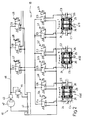
- Fig.2 shows a detailed diagram of hydraulic means 15 for controlling clutches Fp, Fd and actuators A13, A52, A46.
- Said means 15 comprise a hydraulic control system 40 and a number of three-way (intake, delivery, drain) solenoid valves E1,...,E9.
- Control system 40 presents a tank 41, a pump 42, a pressure switch 43 and a bypass valve 44 connected in known manner, and, together with solenoid valves E1,...,E9, is controlled by a microprocessor-based control unit 45.
- Solenoid valves E7, E8, E9 are of the proportional-response type, i.e. designed to provide a delivery pressure varying as a function of an analog signal from control unit 45.
- the inlets of said solenoid valves are connected to a hydraulic feed line 46 from hydraulic system 40 and, in the absence of electric control signals, the delivery outlets of said solenoid valves are connected to a drain outlet.
- solenoid valves E8 and E9 are respectively connected to clutches Fp and Fd, and, as already stated, activation of solenoid valves E8 and E9 provides for releasing clutch Fp and engaging clutch Fd.
- solenoid valve E7 The delivery outlet of solenoid valve E7 is connected to respective inlets of on-off solenoid valves E1,...,E6, the delivery outlets of which are connected to respective chambers C1,...,C6 of actuators A13, A52, A46, which are normally connected to the drain outlet.
- chambers C1,...,C6 are connected to soleniod valve E7.
- Control unit 45 comprises known storage and processing means (therefore, not described in detail) and receives the following input signals:
- control unit 45 As described in more detail later on, in connection with overall operation of transmission 1, the above input signals are processed by control unit 45 to produce the following output signals:
- Control unit 45 is also connected to a display 50 showing which gear is engaged, and an indicator light 51 for indicating any faults on hydraulic control system 40.
- Second stage 3 operates in known manner, and therefore needs no explanation.
- clutches Fd and Fp When engaged, clutches Fd and Fp transmit motion from input shaft 12 to shafts 5 and 4 respectively. Consequently, by virtue of shaft 5 being fitted with gears R1, R3, R5, engagement of clutch Fd enables engagement of the odd number gears. Similarly, by virtue of shaft 4 being fitted with gears R2, R4, R6, engagement of clutch Fp enables engagement of the even number gears. Up or down shifting is thus effected by simultaneously engaging the next and current speed gears on shaft 16, and then shifting both clutches Fp, Fd, which provides for smooth, gradual shift under load.
- proportional-response solenoid valves E8, E9 which provides for appropriately regulating the control pressure of clutches Fp, Fd during engagement or release, as a function of the actual load on the engine, i.e. as a function of service and load conditions of the tractor.
- load conditions in fact, vary substantially should the tractor be connected to a trailer (substantially inertial load) or a plough or similar fixture (low-inertia, high-stress load).
- Control unit 45 accordingly de-energizes solenoid valves E1, E7, and the gear remains engaged by virtue of no axial pressure being exerted on coupling M13 and piston 23 of respective actuator A13.
- control unit 45 subsequent to receiving said signal I2, provides for:
- control unit 45 For switching from one speed range to another, the operator presses pedal 14 of central clutch 13, which enables signal I5; control unit 45 only energizes solenoid valve E8; both clutches Fd, Fp are released; and the speed range is switched as required by means of lever 37.
- control unit 45 When speed range switching with second stage 3 in neutral (zero signals I3) control unit 45 also provides for switching first stage 2 to neutral by releasing the engaged gear as already described, and so enabling speed range switching to be effected with minimum inertia.
- control unit 45 enables signals for automatically re-engaging in stage 2 the most appropriate gear in the selected speed range, as a function of the tractor speed detected by sensor 48.
- the first gear is usually, though not necessarily, engaged when switching to a higher range, and the sixth gear when switching to a lower range.
- pedal 14 of clutch 13 may be released for pulling away.
- clutches Fd, Fp are operated by appropriately increasing or reducing pressure as a function of specific service conditions, and by virtue of proportional-response solenoid valves E8, E9 controlled by control unit 45.
- Gear shifting in first stage 2 is performed simply, effectively and gradually, by virtue of actuators A13, A52, A46, on-off solenoid valves E1,...,E6, and proportional-response solenoid valve E7.
- hydraulic control means 15 are of extremely straightforward design, reliable, compact, and cheap to produce.
Landscapes
- Engineering & Computer Science (AREA)
- General Engineering & Computer Science (AREA)
- Mechanical Engineering (AREA)
- Control Of Transmission Device (AREA)
- Gear-Shifting Mechanisms (AREA)
- Structure Of Transmissions (AREA)
Claims (11)
- Ein Fahrzeuggetriebe (1), insbesondere für einen landwirtschaftlichen Traktor, umfassend eine Eingangswelle (12), zumindest eine erste Stufe (2) mit zwei Triebwellen (4, 5), die selektiv mit der Eingangswelle über entsprechende erste Hydraulikkupplungsmittel (Fp, Fd) verbindbar sind, eine Ausgangswelle (16), die winkelmäßig verbindbar ist mit jeder der Triebwellen (4, 5) über eine Anzahl von Übersetzungsverhältnissen, definiert durch entsprechende dauernd kämmende Zahnräder (R1, ..., R6; R'1, ..., R'6) und zweite selektive Kupplungsmittel (M13, M52, M46) für jedes Paar von benachbarten Zahnrädern (R1, R'1; ..., R6, R'6), betätigt durch zugeordnete hydraulische Dreipositionsaktuatoren (A13, A52, A46) und Steuermittel (15) für das Steuern der ersten Kupplungsmittel und der Aktuatoren, welche Steuermittel (2) erste Solenoid-Ventile (E8, E9) umfassen für das Kuppeln bzw. Lösen eines entsprechenden der ersten Kupplungsmittel (Fp, Fd) auf den Triebwellen (4, 5), zwei zweite ein-aus Solenoid-Ventile (E1, E3; E5, E2; E4, E6) für jeden der hydraulischen Aktuatoren (A13, A52, A46), jeweils ausgelegt zum Steuern des Eingriffs eines entsprechenden Übersetzungsverhältnisses und eine Steuereinheit (45), ausgelegt zur Steuerung zumindest der Solenoid-Ventile (E1, ..., E9), gekennzeichnet durch mindestens ein drittes proportional ansprechendes Solenoid-Ventil (E7) für die Regulierung der Speisung der zweiten Solenoid-Ventile (E1, ..., E6), wobei die ersten Solenoid-Ventile (E8, E9) proportional ansprechende Solenoid-Ventile sind und wobei die Steuereinheit (45) die Solenoid-Ventile (E1; ...; E9) entsprechend vorbestimmten Gesetzmäßigkeiten steuert, die abhängen von den Betriebsbedingungen des Fahrzeugs.
- Ein Getriebe nach Anspruch 1, dadurch gekennzeichnet, daß die ersten Kupplungsmittel eine Kupplung (Fd) umfassen, zugeordnet einer der Triebwellen (5), verbunden mit den Zahnrädern (R1, R3, R5), welche die ungeradzahligen Übertragungsverhältnisse definieren und eine Kupplung (Fp), zugeordnet der anderen Triebwelle (4), verbunden mit den Zahnrädern (R2, R4, R6), welche die geradzahligen Übertragungsverhältnisse definieren, wobei eine der Kupplungen normalerweise eingekuppelt ist und die andere normalerweise gelöst.
- Ein Getriebe nach Anspruch 1 oder 2, dadurch gekennzeichnet, daß mindestens eine (4) der Triebwellen (4, 5) hohl ist, die andere der Triebwellen (5) koaxial und teilweise innerhalb derselben angeordnet ist, daß die Zahnräder eine Anzahl von Zahnrädern (R1, R3, R5; R2, R4, R6) umfassen, die auf jeder der Triebwellen (4, 5) befestigt sind, sowie eine Anzahl von Zahnrädern (R'1, R'3, R'5; R'2, R'4, R'6), die mit denselben kämmen und leerlaufend auf der Ausgangswelle (16) montiert sind, mit der sie über Gleitkupplungen (M13, M52, M46) und Synchronisiermittel in Verbindung bringbar sind, welche die zweiten Kupplungsmittel bilden.
- Ein Getriebe nach einem der vorangehenden Ansprüche, dadurch gekennzeichnet, daß die Eingangswelle (12) durch eine dritte Kupplung (13), gesteuert von einem Pedal (14) angetrieben wird.
- Ein Getriebe nach einem der vorangehenden Ansprüche, dadurch gekennzeichnet, daß es eine zweite Stufe (3) umfaßt, die mit der ersten Stufe (2) in Kaskade verbunden ist und eine Anzahl von Übersetzungsverhältnissen (L, M, V, R) definiert einschließlich zumindest eines Rückwärtsganges und in Kombination mit jedem der Übersetzungsverhältnisse der ersten Stufe (2) über einen handbetätigten Hebel (37) in Verbindung bringbar ist.
- Ein Getriebe nach Anspruch 5, dadurch gekennzeichnet, daß es mit der Steuereinheit (45) verbundene Mittel umfaßt für die Erkennung des Eingriffs eines Übertragungsverhältnisses in der ersten und der zweiten Stufe (2, 3).
- Ein Getriebe nach einem der vorangehenden Ansprüche, dadurch gekennzeichnet, daß es mit der Steuereinheit (45) verbundene Mittel (P) umfaßt für das Auswählen eines Übersetzungsverhältnisses in der ersten Stufe (2).
- Ein Getriebe nach einem der vorangehenden Ansprüche, dadurch gekennzeichnet, daß es mit der Steuereinheit (45) verbundene Mittel (48) umfaßt für die Erfassung der Fahrzeuggeschwindigkeit.
- Ein Getriebe nach einem der vorangehenden Ansprüche 5 bis 8, dadurch gekennzeichnet, daß die Steuereinheit (45) Verarbeitungsmittel aufweist für die Auswahl des Eingriffs eines passenden Übersetzungsverhätnisses in der ersten Stufe (2) nach einer Änderung des Übersetzungsverhältnisses in der zweiten Stufe (3).
- Ein Getriebe nach einem der vorangehenden Ansprüche, dadurch gekennzeichnet, daß es manuelle Steuermittel (47) umfaßt, verbunden mit der Steuereinheit (45) und ausgelegt zum Auswählen des Eingriffs eines höheren oder niedrigeren Übersetzungsverhältnisses relativ zu den gerade eingelegten.
- Ein Getriebe nach einem der vorangehenden Ansprüche 3 bis 10, dadurch gekennzeichnet, daß die Aktuatoren (A13, A52, A46) einen Kolben (23) mit Doppelstange umfassen, verbunden mit einer zugeordneten Kupplung (M13, M52, M46) in der ersten Stufe (2) und gleitbeweglich innerhalb eines zylindrischen Hohlraums (24), ein Paar von Buchsen (26), die in abgedichteter Weise zwischen dem Kolben (23) und den Innenwandungen des Hohlraums (24) gleiten, und Anschlagmittel (27), die zentral auf dem Kolben (23) und der Wandung des Hohlraums (24) angeordnet sind, wobei der Kolben (23) und die Buchsen (26) innerhalb des Hohlraums (24) zwei einander abgekehrte Kammern (C1, C3; C5, C2; C4, C6) begrenzen, verbunden mit entsprechenden ein-aus Solenoid-Ventilen (E1, E3; E5, E2; E4, E6).
Applications Claiming Priority (2)
| Application Number | Priority Date | Filing Date | Title |
|---|---|---|---|
| IT67501/88A IT1219343B (it) | 1988-05-31 | 1988-05-31 | Cambio di velocita per un veicolo particolarmente un trattore agricolo |
| IT6750188 | 1988-05-31 |
Publications (3)
| Publication Number | Publication Date |
|---|---|
| EP0344713A2 EP0344713A2 (de) | 1989-12-06 |
| EP0344713A3 EP0344713A3 (en) | 1990-03-07 |
| EP0344713B1 true EP0344713B1 (de) | 1994-03-02 |
Family
ID=11302950
Family Applications (1)
| Application Number | Title | Priority Date | Filing Date |
|---|---|---|---|
| EP89109735A Expired - Lifetime EP0344713B1 (de) | 1988-05-31 | 1989-05-30 | Fahrzeuggetriebe, insbesondere für Ackerbauschlepper |
Country Status (5)
| Country | Link |
|---|---|
| US (1) | US4957016A (de) |
| EP (1) | EP0344713B1 (de) |
| DE (1) | DE68913356T2 (de) |
| ES (1) | ES2051922T3 (de) |
| IT (1) | IT1219343B (de) |
Families Citing this family (30)
| Publication number | Priority date | Publication date | Assignee | Title |
|---|---|---|---|---|
| US5048655A (en) * | 1990-05-22 | 1991-09-17 | Deere & Company | Electric declutch mechanism for direct drive crawler |
| EP0469451B1 (de) * | 1990-07-25 | 1997-02-05 | CLARK-HURTH COMPONENTS S.p.A. | Getriebe mit drei parallelen Wellen, insbesondere für Nutzfahrzeuge |
| US5044216A (en) * | 1990-08-30 | 1991-09-03 | Eaton Corporation | Transmission shift control |
| DE4031851C2 (de) * | 1990-10-08 | 2001-08-02 | Volkswagen Ag | Stufenwechselgetriebe |
| DE4137143A1 (de) * | 1991-11-12 | 1993-05-13 | Zahnradfabrik Friedrichshafen | Kraftfahrzeuggetriebe |
| US5263379A (en) * | 1991-12-14 | 1993-11-23 | Eaton Corporation | Automatic range shift arrangement |
| IT1266918B1 (it) * | 1994-08-09 | 1997-01-21 | New Holland Fiat Spa | Cambio di velocita' per un veicolo, particolarmente un trattore agricolo. |
| DE19881999D2 (de) * | 1997-12-23 | 2000-06-15 | Luk Getriebe Systeme Gmbh | Getriebe |
| DE19802820C1 (de) * | 1998-01-26 | 1999-12-16 | Getrag Getriebe Zahnrad | Kraftfahrzeug-Stufengetriebe |
| JP2002070961A (ja) * | 2000-08-29 | 2002-03-08 | Aisin Seiki Co Ltd | 平行軸歯車式変速機 |
| AU7736201A (en) * | 2000-10-05 | 2002-04-11 | Komatsu Mining Germany Gmbh | Drive system for a hydraulic excavator |
| US6729454B2 (en) * | 2002-05-06 | 2004-05-04 | Deere & Company | Transmission with a two-step actuator valve |
| DE10349841A1 (de) * | 2003-10-25 | 2005-05-25 | Dr.Ing.H.C. F. Porsche Ag | Mehrstufiges Schaltgetriebe für eine Brennkraftmaschine |
| US6953417B2 (en) * | 2003-11-17 | 2005-10-11 | Borgwarner Inc. | Method for controlling a dual clutch transmission |
| JP4513370B2 (ja) * | 2004-03-22 | 2010-07-28 | 日産自動車株式会社 | ツインクラッチ式マニュアルトランスミッション |
| US7127961B2 (en) * | 2004-07-09 | 2006-10-31 | Borgwarner Inc. | Integrated control module for a dual clutch transmission |
| DE102004043386B4 (de) * | 2004-09-08 | 2013-02-21 | Zf Friedrichshafen Ag | Getriebevorrichtung in Vorgelegebauweise |
| DE102005004339B4 (de) * | 2005-01-25 | 2009-01-08 | Getrag Getriebe- Und Zahnradfabrik Hermann Hagenmeyer Gmbh & Cie Kg | Verwendung eines Stufenwechselgetriebes sowie Verfahren zum Steuern eines solchen |
| DE102005005338B3 (de) * | 2005-01-27 | 2006-08-10 | Getrag Getriebe- Und Zahnradfabrik Hermann Hagenmeyer Gmbh & Cie Kg | Stufenwechselgetriebe |
| EP1729040A1 (de) * | 2005-06-02 | 2006-12-06 | HOERBIGER Antriebstechnik GmbH | Steuereinrichtung zur Schaltbetätigung |
| WO2008055463A2 (de) * | 2006-11-08 | 2008-05-15 | Luk Lamellen Und Kupplungsbau Beteiligungs Kg | Hydraulische steuerung für ein doppelkupplungsgetriebe |
| DE102006061515B4 (de) * | 2006-12-18 | 2010-12-30 | Getrag Getriebe- Und Zahnradfabrik Hermann Hagenmeyer Gmbh & Cie Kg | Doppelkupplungsgetriebe |
| KR101395744B1 (ko) * | 2007-03-02 | 2014-05-16 | 보르그워너 인코퍼레이티드 | 이중 클러치 변속기용 유압 작동식 밸브 장치 |
| CN101946105B (zh) * | 2008-03-04 | 2013-07-17 | 博格华纳公司 | 具有区域控制的离合器冷却回路的双离合器变速器 |
| CN101828055B (zh) * | 2008-04-18 | 2013-09-04 | 博格华纳公司 | 具有简化控制的双离合器变速器 |
| US8376906B2 (en) * | 2008-12-09 | 2013-02-19 | Borgwarner Inc. | Automatic transmission for a hybrid vehicle |
| CN102459965B (zh) | 2009-06-29 | 2014-11-05 | 博格华纳公司 | 用于在自动变速器控制模块中使用的液压阀 |
| US8826760B2 (en) | 2009-12-31 | 2014-09-09 | Borgwarner Inc. | Automatic transmission having high pressure actuation and low pressure lube hydraulic circuit |
| DE102014011921B4 (de) * | 2014-08-12 | 2016-03-17 | Audi Ag | Geschwindigkeits-Wechselgetriebe für ein Kraftfahrzeug |
| US10601188B2 (en) | 2018-08-01 | 2020-03-24 | Cnh Industrial America Llc | Jumper harness with LED |
Citations (1)
| Publication number | Priority date | Publication date | Assignee | Title |
|---|---|---|---|---|
| DE2645907A1 (de) * | 1976-10-12 | 1978-04-13 | Fendt & Co Xaver | Zahnraederwechselgetriebe in gruppenbauweise |
Family Cites Families (16)
| Publication number | Priority date | Publication date | Assignee | Title |
|---|---|---|---|---|
| US3667309A (en) * | 1970-10-14 | 1972-06-06 | Caterpillar Tractor Co | Multi speed drive transmission |
| US3863518A (en) * | 1974-02-01 | 1975-02-04 | Caterpillar Tractor Co | Transmission shifting system |
| JPS54155356A (en) * | 1978-05-29 | 1979-12-07 | Kubota Ltd | Transmission for vehicle |
| FR2446936A1 (fr) * | 1979-01-18 | 1980-08-14 | Renault | Dispositif traducteur electrohydraulique permettant notamment de controler une pression dans une transmission automatique |
| FR2474606A2 (fr) * | 1980-01-24 | 1981-07-31 | Sulzer Ag | Dispositif electrohydraulique rotatif |
| AU537361B2 (en) * | 1981-07-29 | 1984-06-21 | Kubota Ltd. | Transmission with multiple shafts and clutches |
| JPS5844225U (ja) * | 1981-09-11 | 1983-03-24 | 株式会社クボタ | ダブルクラツチ型ミツシヨンのpto装置 |
| US4637269A (en) * | 1982-07-16 | 1987-01-20 | Kubota, Ltd. | Drive apparatus |
| DE3236956A1 (de) * | 1982-10-06 | 1984-04-12 | Klöckner-Humboldt-Deutz AG, 5000 Köln | Zahnraederwechselgetriebe in gruppenbauweise |
| US4560045A (en) * | 1983-04-22 | 1985-12-24 | Ford Motor Company | Transmission control system for a transmission having input shafts clutched to a power source |
| US4513631A (en) * | 1983-06-16 | 1985-04-30 | General Motors Corporation | Dual input clutch transmission |
| JPS6145163A (ja) * | 1984-08-10 | 1986-03-05 | Hitachi Ltd | 自動変速システム |
| DE3431486A1 (de) * | 1984-08-28 | 1986-03-13 | J.M. Voith Gmbh, 7920 Heidenheim | Mit elektronisch gesteuerter drehzahlangleichung ausgeruestetes schaltgetriebe, insbesondere fuer kraftfahrzeuge |
| US4777837A (en) * | 1985-07-06 | 1988-10-18 | Zahnradfabrik Friedrichshafen, Ag. | Power shiftable transmission for vehicle |
| DE3527390A1 (de) * | 1985-07-31 | 1987-02-05 | Klaue Hermann | Stirnradwechselgetriebe mit einer antriebs- und einer die achsantriebswelle bildenden abtriebswelle, insbesondere fuer personenkraftwagen |
| DE3618515C2 (de) * | 1986-06-02 | 1998-05-07 | Klaue Hermann | Kupplungsgeschaltetes Stufengetriebe für Kraftfahrzeuge |
-
1988
- 1988-05-31 IT IT67501/88A patent/IT1219343B/it active
-
1989
- 1989-05-30 ES ES89109735T patent/ES2051922T3/es not_active Expired - Lifetime
- 1989-05-30 DE DE68913356T patent/DE68913356T2/de not_active Expired - Fee Related
- 1989-05-30 EP EP89109735A patent/EP0344713B1/de not_active Expired - Lifetime
-
1990
- 1990-03-22 US US07/497,832 patent/US4957016A/en not_active Expired - Fee Related
Patent Citations (1)
| Publication number | Priority date | Publication date | Assignee | Title |
|---|---|---|---|---|
| DE2645907A1 (de) * | 1976-10-12 | 1978-04-13 | Fendt & Co Xaver | Zahnraederwechselgetriebe in gruppenbauweise |
Also Published As
| Publication number | Publication date |
|---|---|
| EP0344713A2 (de) | 1989-12-06 |
| DE68913356D1 (de) | 1994-04-07 |
| ES2051922T3 (es) | 1994-07-01 |
| DE68913356T2 (de) | 1994-09-01 |
| US4957016A (en) | 1990-09-18 |
| EP0344713A3 (en) | 1990-03-07 |
| IT8867501A0 (it) | 1988-05-31 |
| IT1219343B (it) | 1990-05-11 |
Similar Documents
| Publication | Publication Date | Title |
|---|---|---|
| US4957016A (en) | Vehicle transmission, particularly for an agricultural tractor | |
| JP3593633B2 (ja) | 3位置シフトアクチュエータ | |
| EP0696695B1 (de) | Fahrzeuggetriebe, insbesondere für landwirtschaftliche Schlepper | |
| EP1961996B1 (de) | Drehzahlwechselsystem für Nutzfahrzeuge | |
| KR100366728B1 (ko) | 3위치액츄에이터피스톤조립체및이를이용한액츄에이터시스템 | |
| JPH04302774A (ja) | 変速機の入力部シフト用制御装置およびその制御方法 | |
| EP0127949B1 (de) | Getriebe-Schaltsystem | |
| JP2002174339A (ja) | ハイドロリック式作動装置 | |
| US5433125A (en) | Gear shift mechanism of a motor vehicle transmission | |
| JP2844493B2 (ja) | 機械式変速装置のためのシフト実行制御装置及び方法 | |
| EP0387275B1 (de) | Steuersystem für automatisches getriebe, in dem der gangwechsel stufenweise erfolgt | |
| JPS6331029B2 (de) | ||
| US6990871B2 (en) | Selector transmission for a motor vehicle | |
| US6319164B1 (en) | Electro-hydraulic control with a manual selection valve | |
| CZ6293A3 (en) | Method of controlling a gear shifting controller and a system for controlling thereof | |
| EP1035357B1 (de) | Schaltgetriebe für ein Nutzfahrzeug | |
| JP2001349417A (ja) | 複合型歯車変速機用の制御システム | |
| CN108291631B (zh) | 双离合器式变速器的控制装置和双离合器式变速器 | |
| US3548981A (en) | Power shift transmission having synchronized clutch control | |
| US6131475A (en) | Gear control system for a synchro-shuttle gear or power shift gear | |
| GB2239910A (en) | Hydraulically operable transmission including two switch valves in parallel with a restrictor | |
| CA1112542A (en) | Detent release for power shift transmission selector valve | |
| EP1184597A2 (de) | Biaxialartiges Getriebe | |
| EP3203121B1 (de) | Kupplungsverbindungs-/-trennungsvorrichtung für doppelkupplungsgetriebe | |
| KR19980020767A (ko) | 자동차 4륜 구동장치용 트랜스퍼의 버튼시프트시스템 |
Legal Events
| Date | Code | Title | Description |
|---|---|---|---|
| PUAI | Public reference made under article 153(3) epc to a published international application that has entered the european phase |
Free format text: ORIGINAL CODE: 0009012 |
|
| AK | Designated contracting states |
Kind code of ref document: A2 Designated state(s): DE ES FR GB |
|
| PUAL | Search report despatched |
Free format text: ORIGINAL CODE: 0009013 |
|
| AK | Designated contracting states |
Kind code of ref document: A3 Designated state(s): DE ES FR GB |
|
| 17P | Request for examination filed |
Effective date: 19900716 |
|
| 17Q | First examination report despatched |
Effective date: 19920702 |
|
| GRAA | (expected) grant |
Free format text: ORIGINAL CODE: 0009210 |
|
| AK | Designated contracting states |
Kind code of ref document: B1 Designated state(s): DE ES FR GB |
|
| REF | Corresponds to: |
Ref document number: 68913356 Country of ref document: DE Date of ref document: 19940407 |
|
| REG | Reference to a national code |
Ref country code: ES Ref legal event code: FG2A Ref document number: 2051922 Country of ref document: ES Kind code of ref document: T3 |
|
| ET | Fr: translation filed | ||
| PLBE | No opposition filed within time limit |
Free format text: ORIGINAL CODE: 0009261 |
|
| STAA | Information on the status of an ep patent application or granted ep patent |
Free format text: STATUS: NO OPPOSITION FILED WITHIN TIME LIMIT |
|
| 26N | No opposition filed | ||
| PGFP | Annual fee paid to national office [announced via postgrant information from national office to epo] |
Ref country code: GB Payment date: 19960520 Year of fee payment: 8 |
|
| PGFP | Annual fee paid to national office [announced via postgrant information from national office to epo] |
Ref country code: FR Payment date: 19960528 Year of fee payment: 8 |
|
| PGFP | Annual fee paid to national office [announced via postgrant information from national office to epo] |
Ref country code: ES Payment date: 19960531 Year of fee payment: 8 |
|
| PGFP | Annual fee paid to national office [announced via postgrant information from national office to epo] |
Ref country code: DE Payment date: 19960709 Year of fee payment: 8 |
|
| PG25 | Lapsed in a contracting state [announced via postgrant information from national office to epo] |
Ref country code: GB Effective date: 19970530 |
|
| PG25 | Lapsed in a contracting state [announced via postgrant information from national office to epo] |
Ref country code: ES Free format text: LAPSE BECAUSE OF NON-PAYMENT OF DUE FEES Effective date: 19970531 |
|
| GBPC | Gb: european patent ceased through non-payment of renewal fee |
Effective date: 19970530 |
|
| PG25 | Lapsed in a contracting state [announced via postgrant information from national office to epo] |
Ref country code: FR Free format text: LAPSE BECAUSE OF NON-PAYMENT OF DUE FEES Effective date: 19980130 |
|
| PG25 | Lapsed in a contracting state [announced via postgrant information from national office to epo] |
Ref country code: DE Free format text: LAPSE BECAUSE OF NON-PAYMENT OF DUE FEES Effective date: 19980203 |
|
| REG | Reference to a national code |
Ref country code: FR Ref legal event code: ST |
|
| REG | Reference to a national code |
Ref country code: ES Ref legal event code: FD2A Effective date: 19990405 |