EP0344587A2 - Gehäuse in Inline-Bauart - Google Patents
Gehäuse in Inline-Bauart Download PDFInfo
- Publication number
- EP0344587A2 EP0344587A2 EP89109316A EP89109316A EP0344587A2 EP 0344587 A2 EP0344587 A2 EP 0344587A2 EP 89109316 A EP89109316 A EP 89109316A EP 89109316 A EP89109316 A EP 89109316A EP 0344587 A2 EP0344587 A2 EP 0344587A2
- Authority
- EP
- European Patent Office
- Prior art keywords
- housing
- suction
- intermediate wall
- pressure
- halves
- Prior art date
- Legal status (The legal status is an assumption and is not a legal conclusion. Google has not performed a legal analysis and makes no representation as to the accuracy of the status listed.)
- Granted
Links
Images
Classifications
-
- F—MECHANICAL ENGINEERING; LIGHTING; HEATING; WEAPONS; BLASTING
- F04—POSITIVE - DISPLACEMENT MACHINES FOR LIQUIDS; PUMPS FOR LIQUIDS OR ELASTIC FLUIDS
- F04D—NON-POSITIVE-DISPLACEMENT PUMPS
- F04D29/00—Details, component parts, or accessories
- F04D29/40—Casings; Connections of working fluid
- F04D29/42—Casings; Connections of working fluid for radial or helico-centrifugal pumps
- F04D29/426—Casings; Connections of working fluid for radial or helico-centrifugal pumps especially adapted for liquid pumps
- F04D29/4266—Casings; Connections of working fluid for radial or helico-centrifugal pumps especially adapted for liquid pumps made of sheet metal
-
- F—MECHANICAL ENGINEERING; LIGHTING; HEATING; WEAPONS; BLASTING
- F04—POSITIVE - DISPLACEMENT MACHINES FOR LIQUIDS; PUMPS FOR LIQUIDS OR ELASTIC FLUIDS
- F04D—NON-POSITIVE-DISPLACEMENT PUMPS
- F04D29/00—Details, component parts, or accessories
- F04D29/40—Casings; Connections of working fluid
- F04D29/42—Casings; Connections of working fluid for radial or helico-centrifugal pumps
- F04D29/426—Casings; Connections of working fluid for radial or helico-centrifugal pumps especially adapted for liquid pumps
Definitions
- the invention relates to a housing according to the preamble of the main claim.
- an inline housing for single-stage pumps which consists of two mold halves, the parting plane of which lies in the plane of the pump shaft.
- the use of a spiral housing shown requires two different housing halves, which is why two different tools are always required to produce the housing halves for the different sizes of a series.
- An intermediate wall inserted into the housing is connected to the two housing halves in a plane running transversely to the division plane. This requires additional effort, since these parts have to be subsequently inserted into a housing that has already been produced and reliably connected there.
- an in-line design of the pot housing is provided with molded nozzles and is also equipped with a partition wall which is inserted subsequently.
- This intermediate housing has at the same time a connection flange for receiving a drive motor and is provided on the side opposite the motor with contact surfaces for a plurality of downstream step housings.
- a connection flange for receiving a drive motor and is provided on the side opposite the motor with contact surfaces for a plurality of downstream step housings.
- Within the intermediate housing there is a separation between the suction and pressure chamber, and a shaft bushing and shaft seal are provided on the intermediate wall.
- the invention has for its object to develop a housing for single or multi-stage pumps in inline design, which can easily absorb and transmit pipeline forces acting on the housing with a simple structure and less expensive manufacture. This object is achieved in accordance with the characterizing part of the main claim.
- assembly is extremely simple, since the three individual parts forming the housing can be positioned with little effort and can be connected to one another in one setting. This can be done by gluing, soldering, welding or the like. It has the advantage that the joining seam runs only in one plane and the joining process can be carried out easily using automatic machines. For this purpose, the intermediate wall and / or the housing parts lying on the intermediate wall can protrude beyond the housing contour with the aid of an attached flange and can thus be available for welding at the same time.
- One embodiment of the invention provides that the two housing halves are mirror images, the housing half forming the pressure chamber having a central opening in its bottom region.
- both housing halves can be created with one mold or one tool.
- the suction and pressure nozzle parts attached to the intermediate wall rest against and / or protrude into the suction and pressure nozzles formed by the housing halves.
- the suction and pressure connector parts of the intermediate wall can interact with the suction and pressure connectors of the housing in the most advantageous manner in each case.
- suction and pressure nozzle parts attached to the intermediate wall are longitudinally divided in the direction of the joining plane.
- a downstream pump or stage housing seals against the opening of the intermediate wall or, in a known manner, the opening of the intermediate wall forms a corresponding throttle gap for an impeller.
- the inline design of the housing is connected to downstream components by known means.
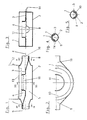
- the housing shown in Fig. 1 in inline design consists of two identical housing halves (1, 2), for the manufacture of which only one mold is required.
- An intermediate wall (3) which is arranged in the joining plane (4) of the two housing halves (1, 2), divides the interior of the housing into a suction chamber (5) and a pressure chamber (6).
- Suction nozzle parts (7) and pressure nozzle parts (8) attached to the intermediate wall (3) are arranged alternately with respect to the joining plane (4).
- the integrally formed, longitudinally divided and channel-shaped suction nozzle part (7) is located above the joining plane (4) and extends completely into the suction nozzle (9) formed by the two housing halves.
- the correspondingly designed pressure connection part (8) lies in the exemplary embodiment below the joining plane (4) and within the pressure connection (10).
- An opening (11) made within the intermediate wall (3) enables an overflow from the suction chamber into the pressure chamber, wherein the opening (11) can be followed by an impeller or - as shown in dashed lines - a step housing (12).
- the upper housing half (1) has a central opening (13), which can be easily manufactured using a simple punching tool.
- the intermediate wall arranged in the joining plane enables direct frictional connection between the suction and pressure ports, the inclusion of the connector parts attached to the intermediate wall in the connectors attached to the housing representing an optimum in terms of strength.
- Fig. 2 shows a plan view of the housing in-line design, in particular on the housing half (1), the opening (13) with the underlying partition (3) and the opening (11) made therein.
- FIG. 3 corresponds to a section III-III from FIG. 1.
- the joining plane (4) there is the intermediate wall (3) against which the two housing halves (1, 2) rest.
- the housing halves In the area of the intermediate wall, the housing halves have small flange surfaces (14) by means of which the parts shown can be firmly connected by welding, gluing, soldering or the like. If the parts are welded together, the parts of the partition (3) and the flange surfaces (14) protruding from the housing can be used as material for the weld seam.
- FIG. 4 and 5 corresponds to a section along the sectional planes IV-IV and VV from FIG. 1.
- FIG. 4 how flow-favorably the suction nozzle part (7) formed on the intermediate wall (3) within the two halves of the housing ( 1, 2) suction port is arranged.
- FIG. 5 the mutual course of the pressure nozzle part (8) attached to the intermediate wall (3) can be seen. It is shaped downwards so as to allow an outflow from the pressure chamber into the pressure port (10).
Landscapes
- Engineering & Computer Science (AREA)
- Mechanical Engineering (AREA)
- General Engineering & Computer Science (AREA)
- Structures Of Non-Positive Displacement Pumps (AREA)
- Piezo-Electric Or Mechanical Vibrators, Or Delay Or Filter Circuits (AREA)
- Flexible Shafts (AREA)
Abstract
Description
- Die Erfindung betrifft ein Gehäuse gemäß dem Oberbegriff des Hauptanspruches.
- Aus der DE-PS 32 10 526 ist ein Inline-Gehäuse für einstufige Pumpen bekannt, welches aus zwei Formhälften besteht, deren Teilungsebene in der Ebene der Pumpenwelle liegt. Die gezeigte Verwendung eines Spiralgehäuses bedingt zwei unterschiedliche Gehäuseformhälften, weshalb für die unterschiedlichen Größen einer Baureihe immer zwei verschiedene Werkzeuge zur Herstellung der Gehäusehälften erforderlich sind. Eine in das Gehäuse eingelegte Zwischenwand wird in einer quer zur Teilungsebene verlaufenden Ebene mit den beiden Gehäusehälften verbunden. Dies erfordert einen zusätzlichen Aufwand, da diese Teile nachträglich in ein bereits hergestelltes Gehäuse eingelegt und dort zuverlässig verbunden werden müssen. Bei der Konstruktion gemäß der US-PS 30 59 582 ist ein nach Inline-Bauart ausgeführtes Topfgehäuse mit angeformten Stutzen versehen und ebenfalls mit einer nachträglich eingelegten Zwischenwand ausgerüstet.
- Für eine mehrstufige Kreiselpumpe in Inline-Bauart ist aus der DE-PS 27 07 776 eine Lösung bekannt, derzufolge ein als Spritzguß- oder Gußkonstruktion ausgebildetes Zwischengehäuse in Inline-Bauart mit integrierter Zwischenwand versehen ist.
- Dieses Zwischengehäuse weist gleichzeitig einen Anschlußflansch zur Aufnahme eines Antriebsmotors auf und ist an der dem Motor gegenüberliegenden Seite mit Anlageflächen für mehrere nachgeordnete Stufengehäuse versehen. Innerhalb des Zwischengehäuses erfolgt eine Trennung zwischen Saug- und Druckraum sowie an der Zwischwand die Vorsehung einer Wellendurchführung und einer Wellenabdichtung.
- Der Erfindung liegt die Aufgabe zugrunde, für ein- oder mehrstufige Pumpen ein Gehäuse in Inline-Bauart zu entwickeln, welches bei einfachem Aufbau und wenig aufwendiger Herstellung auf das Gehäuse einwirkende Rohrleitungskräfte zuverlässig aufnehmen und weiterleiten kann. Die Lösung dieser Aufgabe erfolgt gemäß dem kennzeichnenden Teil des Hauptanspruches.
- Infolge dieser Lösung ergibt sich eine äußerst einfache Montage, da die das Gehäuse bildenden drei Einzelteile wenig aufwendig zu positionieren sind und in einer Aufspannung miteinander verbunden werden können. Dies kann durch Kleben, Löten, Schweißen oder dgl. erfolgen und hat den Vorteil, daß die Fügenaht nur in einer Ebene verläuft und unter Verwendung von Automaten der Fügevorgang leicht vollziehbar ist. Zu diesem Zweck kann die Zwischenwand und/oder die an der Zwischenwand liegenden Gehäuseteile mit Hilfe eines angebrachten Flansches über die Gehäusekontur hinausragen und somit gleichzeitig für eine Verschweißung zur Verfügung stehen. Infolge der an der Zwischenwand angebrachten Saug- und Druckstutzenteile ist neben der Möglichkeit einer verlustarmen Strömungsführung der Vorteil gegeben, daß ein direkter Kraftfluß beispielsweise vom Gehäusesaugstutzen über den Saugstutzenteil der Zwischenwand direkt auf die Zwischenwand und von dieser über den Druckstutzenteil der Zwischenwand auf den Druckstutzen des Gehäuses erfolgen kann. Die Zwischenwand übt somit eine außerordentliche Versteifungsfunktion auf das Gehäuse aus und vermeidet infolge der angebrachten Saug- und Druckstutzenteile bei einer Belastung durch Rohrleitungskräfte eine Verformung des Gehäuses.
- Eine Ausgestaltung der Erfindung sieht vor, daß die beiden Gehäusehälften spiegelbildlich ausgebildet sind, wobei die den Druckraum bildende Gehäusehälfte in ihrem Bodenbereich eine mittige Öffnung aufweist. Infolge dieser Maßnahme können mit einer Form bzw. einem Werkzeug beide Gehäusehälften erstellt werden. Zwecks Verbindung mit einem dem Gehäuse nachgeordneten Pumpengehäuse oder Stufengehäuse, wie bei mehrstufigen Kreiselpumpen, genügt es, eine der Gehäusehälften mit einer einfach auszustanzenden mittigen Öffnung zu versehen, welche eine Verbindung mit einem nachgeschalteten Laufrad oder Stufengehäuse ermöglicht.
- Nach einer weiteren Ausgestaltung der Erfindung liegen die an der Zwischenwand angebrachten Saug- und Druckstutzenteile an den von den Gehäusehälften gebildeten Saug- und Druckstutzen an und/oder ragen in diese hinein. Je nach der im Einzelfall günstigsten Formgebung sowie den erforderlichen Dichtheitsanforderungen können die Saug- und Druckstutzenteile der Zwischenwand in der jeweils vorteilhaftesten Weise mit den Saug- und Druckstutzen des Gehäuses zusammenwirken.
- Eine vorteilhafte Ausgestaltung der Erfindung sieht hierzu vor, daß die an der Zwischenwand angebrachten Saug- und Druckstutzenteile in Richtung der Fügeebene längsgeteilt sind. Infolge des gegenüber der Fügeebene wechselseitigen Verlaufes und der in Richtung der Fügeebene längsgeteilten Saug- und Druckstutzenteile wird neben einer leichten Formbarkeit, beispielsweise im Wege des Tiefziehens, ein äußerst günstiger Kraftfluß innerhalb des Gehäuses erzeugt. Hierbei erfolgt eine direkte Kräfteübertragung zwischen den einander gegenüberliegenden Stutzen.
- Nach einer weiteren Ausgestaltung der Erfindung liegt an der Öffnung der Zwischenwand dichtend ein nachgeschaltetes Pumpen- oder Stufengehäuse an bzw. in bekannter Weise bildet die Öffnung der Zwischenwand für ein Laufrad einen entsprechenden Drosselspalt. Die Verbindung des Gehäuses in Inline-Bauart mit nachgeschalteten Bauteilen erfolgt durch bekannte Mittel.
- Ein Ausführungsbeispiel der Erfindung ist in den Fig. 1 bis 5 dargestellt und wird im folgenden näher beschrieben. Es zeigen die
- Fig. 1 einen in Strömungsrichtung verlaufenden Querschnitt durch das Gehäuse, die
- Fig. 2 eine Draufsicht, die
- Fig. 3 eine Seitenansicht im Schnitt und die
- Fig. 4 und 5 Schnittdarstellungen von Saug- und Druckstutzen.
- Das in der Fig. 1 gezeigte Gehäuse in Inline-Bauart besteht aus zwei baugleichen Gehäusehälften (1, 2), zu deren Herstellung nur ein Formwerkzeug erforderlich ist. Eine Zwischenwand (3), welche in der Fügeebene (4) der beiden Gehäusehälften (1, 2) angeordnet ist, unterteilt das Gehäuseinnere in einen Saugraum (5) und einen Druckraum (6). An der Zwischenwand (3) angebrachte Saugstutzenteile (7) sowie Druckstutzenteile (8) sind gegenüber der Fügeebene (4) wechselseitig angeordnet. Bei dem hier gezeigten Ausführungsbeispiel befindet sich der angeformte, längsgeteilte und rinnenförmige Saugstutzenteil (7) oberhalb der Fügeebene (4) und erstreckt sich vollständig in den von den beiden Gehäusehälften gebildeten Saugstutzen (9). Der entsprechend ausgebildete Druckstutzenteil (8) liegt in dem Ausführungsbeispiel unterhalb der Fügeebene (4) und innerhalb des Druckstutzens (10). Eine innerhalb der Zwischenwand (3) angebrachte Öffnung (11) ermöglicht ein Überströmen vom Saugraum in den Druckraum, wobei der Öffnung (11) ein Laufrad oder - wie gestrichelt dargestellt - ein Stufengehäuse (12) nachgeordnet sein kann. Zur Anbringung derselben weist die hier obere Gehäusehälfte (1) eine mittige Öffnung (13) auf, welche mit Hilfe eines einfachen Stanzwerkzeuges leicht herstellbar ist.
- Die in der Fügeebene angeordnete Zwischenwand ermöglicht einen direkten Kraftschluß zwischen Saug- und Druckstutzen, wobei die Einbeziehung der an der Zwischenwand angebrachten Stutzenteile in die am Gehäuse angebrachten Stutzen ein festigkeitsmäßiges Optimum darstellt.
- Die Fig. 2 zeigt eine Draufsicht auf das Gehäuse in Inline-Bauart, insbesondere auf die Gehäusehälfte (1), deren Öffnung (13) mit der darunterliegenden Zwischenwand (3) und der darin angebrachten Öffnung (11).
- Die Fig. 3 entspricht einem Schnitt III-III aus Fig. 1. In der Fügeebene (4) befindet sich die Zwischenwand (3), an der die beiden Gehäusehälften (1, 2) anliegen. Im Bereich der Zwischenwand weisen die Gehäusehälften kleine Flanschflächen (14) auf, mit deren Hilfe die gezeigten Teile durch Schweißen, Kleben, Löten oder dgl. fest verbunden werden können. Bei einem eventuellen Verschweißen der Teile können die aus dem Gehäuse hervorstehenden Teile der Zwischenwand (3) sowie der Flanschflächen (14) als Material für die Schweißnaht benutzt werden.
- Fig. 4 und 5 entspricht einem Schnitt gemäß den Schnittebenen IV-IV und V-V aus Fig. 1. Hierbei ist gemäß Fig. 4 erkennbar, wie Strömungsgünstig der an der Zwischenwand (3) angeformte Saugstutzenteil (7) innerhalb des von den beiden Gehäusehälften (1, 2) gebildeten Saugstutzens angeordnet ist. Gemäß Fig. 5 ist der gegenüber Fig. 4 wechselseitige Verlauf des an der Zwischenwand (3) angebrachten Druckstutzenteiles (8) erkennbar. Es ist hier nach unten ausgeformt, um so einen Ausfluß aus dem Druckraum in den Druckstutzen (10) zu ermöglichen. Infolge der erfindungsgemäßen Ausbildung der Zwischenwand ist sichergestellt, daß beim Fügevorgang der Gehäusehälften auch gleichzeitig eine flüssigkeitsdichte Verbindung zwischen Saug- und Druckraum erfolgt.
Claims (6)
Priority Applications (1)
| Application Number | Priority Date | Filing Date | Title |
|---|---|---|---|
| AT89109316T ATE82046T1 (de) | 1988-06-01 | 1989-05-24 | Gehaeuse in inline-bauart. |
Applications Claiming Priority (2)
| Application Number | Priority Date | Filing Date | Title |
|---|---|---|---|
| DE3818651A DE3818651A1 (de) | 1988-06-01 | 1988-06-01 | Gehaeuse in inline-bauart |
| DE3818651 | 1988-06-01 |
Publications (3)
| Publication Number | Publication Date |
|---|---|
| EP0344587A2 true EP0344587A2 (de) | 1989-12-06 |
| EP0344587A3 EP0344587A3 (en) | 1990-03-07 |
| EP0344587B1 EP0344587B1 (de) | 1992-11-04 |
Family
ID=6355620
Family Applications (1)
| Application Number | Title | Priority Date | Filing Date |
|---|---|---|---|
| EP89109316A Expired - Lifetime EP0344587B1 (de) | 1988-06-01 | 1989-05-24 | Gehäuse in Inline-Bauart |
Country Status (5)
| Country | Link |
|---|---|
| US (1) | US5030061A (de) |
| EP (1) | EP0344587B1 (de) |
| AT (1) | ATE82046T1 (de) |
| DE (1) | DE3818651A1 (de) |
| ES (1) | ES2036749T3 (de) |
Families Citing this family (12)
| Publication number | Priority date | Publication date | Assignee | Title |
|---|---|---|---|---|
| US5161939A (en) * | 1991-07-12 | 1992-11-10 | Turbo Concepts, Inc. | Air compression system |
| EP0717195B1 (de) * | 1992-04-14 | 2000-11-08 | Ebara Corporation | Pumpengehäuse in Blechbauweise |
| SE503510C2 (sv) * | 1993-05-17 | 1996-07-01 | Hans Oestberg | Hus för kanalfläkt av radialtyp, vilket hus vid monteringen låser motorbryggan med den vid denna monterade fläktmotorn och dess radialfläkthjul på rätt plats i huset |
| DE19506854A1 (de) * | 1995-03-01 | 1996-09-05 | Wilo Gmbh | Kreiselpumpe |
| DE19855845A1 (de) * | 1998-12-03 | 2000-06-08 | Gep Umwelttechnik Gmbh | Selbstansaugendes Motorpumpenaggregat |
| AU2003208007A1 (en) * | 2002-02-13 | 2003-09-04 | Ebara Corporation | Pump casing and pump apparatus |
| US7290981B2 (en) * | 2005-03-10 | 2007-11-06 | Field Controls, Llc | Inline vent fan |
| GB201212213D0 (en) * | 2012-07-06 | 2012-08-22 | Salamander Pumped Shower Systems Ltd | Improvements in pump assemblies |
| ITPD20120284A1 (it) * | 2012-10-02 | 2014-04-03 | Dab Pumps Spa | Struttura di elettropompa centrifuga perfezionata |
| JP5686827B2 (ja) * | 2013-01-23 | 2015-03-18 | 株式会社鷺宮製作所 | 遠心ポンプ |
| JP6166301B2 (ja) * | 2014-07-22 | 2017-07-19 | 株式会社鷺宮製作所 | 遠心ポンプ |
| EP3176441B1 (de) * | 2015-12-02 | 2021-09-15 | Grundfos Holding A/S | Mehrstufige pumpe |
Family Cites Families (16)
| Publication number | Priority date | Publication date | Assignee | Title |
|---|---|---|---|---|
| US898493A (en) * | 1908-09-15 | Rotaby air-pump | ||
| CA640951A (en) * | 1962-05-08 | Egli Hans | Turbine housing | |
| US3037458A (en) * | 1957-04-15 | 1962-06-05 | Goulds Pumps | Glass pump |
| DE1089637B (de) * | 1958-12-12 | 1960-09-22 | Teves Kg Alfred | OElpumpe fuer Kapselkompressoren, deren Rotor als Fluegelrad ausgebildet ist |
| US3059582A (en) * | 1959-04-24 | 1962-10-23 | Bell & Gossett Co | Motor pump unit |
| US2997958A (en) * | 1960-06-13 | 1961-08-29 | Heinicke Pump Co | Centrifugal pump |
| US3269703A (en) * | 1960-08-30 | 1966-08-30 | Sundstrand Corp | Gas turbine engine starter |
| DE1703908A1 (de) * | 1968-07-27 | 1972-03-23 | Grundfos As | Pumpengehaeuse fuer Kreiselpumpen |
| FR2342416A1 (fr) * | 1976-02-27 | 1977-09-23 | Materiel Telephonique | Pompe centrifuge multicellulaire auto-amorcante |
| DE2750967C2 (de) * | 1977-11-15 | 1979-12-06 | Flutec Fluidtechnische Geraete Gmbh, 6603 Sulzbach | Vorrichtung zum Verbinden eines Antriebsmotors und einer Pumpe |
| DE3210526C1 (de) * | 1982-03-23 | 1983-10-06 | Grundfos As | Gehaeuse fuer einstufige Kreiselpumpen |
| US4448573A (en) * | 1982-03-25 | 1984-05-15 | General Electric Company | Single-stage, multiple outlet centrifugal blower |
| DE3220448C1 (de) * | 1982-05-29 | 1983-08-11 | Grundfos A/S, 8850 Bjerringbro | Pumpenaggregat fuer Heizungs- und Brauchwasseranlagen |
| US4530640A (en) * | 1982-09-29 | 1985-07-23 | Roto-Master, Inc. | Method and apparatus for wastegating turbocharged engine with divided exhaust system |
| DE3302186A1 (de) * | 1983-01-24 | 1984-07-26 | Klöckner-Humboldt-Deutz AG, 5000 Köln | Abgasturbolader fuer brennkraftmaschinen |
| DE3622269A1 (de) * | 1986-07-03 | 1988-01-14 | Richard Halm | Spaltrohrmotorpumpe |
-
1988
- 1988-06-01 DE DE3818651A patent/DE3818651A1/de active Granted
-
1989
- 1989-05-24 AT AT89109316T patent/ATE82046T1/de not_active IP Right Cessation
- 1989-05-24 ES ES198989109316T patent/ES2036749T3/es not_active Expired - Lifetime
- 1989-05-24 EP EP89109316A patent/EP0344587B1/de not_active Expired - Lifetime
-
1990
- 1990-05-31 US US07/532,347 patent/US5030061A/en not_active Expired - Fee Related
Also Published As
| Publication number | Publication date |
|---|---|
| DE3818651A1 (de) | 1989-12-07 |
| EP0344587B1 (de) | 1992-11-04 |
| ES2036749T3 (es) | 1993-06-01 |
| US5030061A (en) | 1991-07-09 |
| ATE82046T1 (de) | 1992-11-15 |
| EP0344587A3 (en) | 1990-03-07 |
| DE3818651C2 (de) | 1990-05-03 |
Similar Documents
| Publication | Publication Date | Title |
|---|---|---|
| DE2848887C2 (de) | ||
| DE2046486C3 (de) | Schaufelrad für Lüfter | |
| EP0344587B1 (de) | Gehäuse in Inline-Bauart | |
| DE2301297A1 (de) | Anordnung zur verbindung einer welle mit einer kardangelenkgabel | |
| DE3603423C2 (de) | ||
| DE2748431C2 (de) | Schnappverbindung an spritzgegossenen Gehäuseteilen | |
| DE69419544T2 (de) | Wirbelstromgebläse und Schaufelrad | |
| DE3319301A1 (de) | Verfahren zur herstellung eines kompressors in spiralbauweise | |
| EP4467860A2 (de) | Verwendung eines schlauchs zur fluidischen verbindung eines auslaufstücks mit einem ventil an einer sanitärarmatur, fluidische anordnung und korrespondierende sanitärarmatur | |
| EP0241659A1 (de) | Laufrad für eine Radialpumpe | |
| DE3048984A1 (de) | Rotationslaufradpumpe oder -motor | |
| EP0425613B1 (de) | Doppelförderpumpe, insbesondere für scheibenwaschanlagen in kraftfahrzeugen | |
| DE3210526C1 (de) | Gehaeuse fuer einstufige Kreiselpumpen | |
| EP0713975B1 (de) | Seitenkanalverdichter | |
| DE19908143C2 (de) | Geschmiedetes Kreiselpumpengehäuse | |
| DE102019212283A1 (de) | Kern für ein Gehäuse eines Ventils und Verfahren zur Herstellung des Kerns | |
| DE4113831A1 (de) | Geteiltes laufrad | |
| DE2262017B2 (de) | Vertikale, haengende kreiselpumpe | |
| DE3301563C2 (de) | Zweikreispumpe | |
| DE8124287U1 (de) | Unterdruckstellantrieb | |
| DE3622377A1 (de) | Druckstueck fuer eine fahrzeuglenkvorrichtung | |
| DE69627925T2 (de) | Drehantrieb | |
| DE3316927A1 (de) | Kreiselpumpe | |
| DE3931427A1 (de) | Fluessigkeitskupplung, wie foettinger-kupplung oder drehmomentwandler | |
| DE3143494C2 (de) |
Legal Events
| Date | Code | Title | Description |
|---|---|---|---|
| PUAI | Public reference made under article 153(3) epc to a published international application that has entered the european phase |
Free format text: ORIGINAL CODE: 0009012 |
|
| AK | Designated contracting states |
Kind code of ref document: A2 Designated state(s): AT BE CH ES FR GB GR IT LI LU NL SE |
|
| PUAL | Search report despatched |
Free format text: ORIGINAL CODE: 0009013 |
|
| AK | Designated contracting states |
Kind code of ref document: A3 Designated state(s): AT BE CH ES FR GB GR IT LI LU NL SE |
|
| 17P | Request for examination filed |
Effective date: 19900823 |
|
| 17Q | First examination report despatched |
Effective date: 19910729 |
|
| GRAA | (expected) grant |
Free format text: ORIGINAL CODE: 0009210 |
|
| AK | Designated contracting states |
Kind code of ref document: B1 Designated state(s): AT BE CH ES FR GB GR IT LI LU NL SE |
|
| PG25 | Lapsed in a contracting state [announced via postgrant information from national office to epo] |
Ref country code: GR Free format text: LAPSE BECAUSE OF FAILURE TO SUBMIT A TRANSLATION OF THE DESCRIPTION OR TO PAY THE FEE WITHIN THE PRESCRIBED TIME-LIMIT Effective date: 19921104 |
|
| REF | Corresponds to: |
Ref document number: 82046 Country of ref document: AT Date of ref document: 19921115 Kind code of ref document: T |
|
| ET | Fr: translation filed | ||
| GBT | Gb: translation of ep patent filed (gb section 77(6)(a)/1977) |
Effective date: 19921222 |
|
| ITF | It: translation for a ep patent filed | ||
| REG | Reference to a national code |
Ref country code: ES Ref legal event code: FG2A Ref document number: 2036749 Country of ref document: ES Kind code of ref document: T3 |
|
| PLBE | No opposition filed within time limit |
Free format text: ORIGINAL CODE: 0009261 |
|
| STAA | Information on the status of an ep patent application or granted ep patent |
Free format text: STATUS: NO OPPOSITION FILED WITHIN TIME LIMIT |
|
| 26N | No opposition filed | ||
| EPTA | Lu: last paid annual fee | ||
| EAL | Se: european patent in force in sweden |
Ref document number: 89109316.3 |
|
| PGFP | Annual fee paid to national office [announced via postgrant information from national office to epo] |
Ref country code: GB Payment date: 19990504 Year of fee payment: 11 |
|
| PGFP | Annual fee paid to national office [announced via postgrant information from national office to epo] |
Ref country code: ES Payment date: 19990517 Year of fee payment: 11 |
|
| PGFP | Annual fee paid to national office [announced via postgrant information from national office to epo] |
Ref country code: FR Payment date: 19990518 Year of fee payment: 11 |
|
| PGFP | Annual fee paid to national office [announced via postgrant information from national office to epo] |
Ref country code: LU Payment date: 19990520 Year of fee payment: 11 |
|
| PGFP | Annual fee paid to national office [announced via postgrant information from national office to epo] |
Ref country code: BE Payment date: 19990526 Year of fee payment: 11 Ref country code: AT Payment date: 19990526 Year of fee payment: 11 |
|
| PGFP | Annual fee paid to national office [announced via postgrant information from national office to epo] |
Ref country code: SE Payment date: 19990527 Year of fee payment: 11 |
|
| PGFP | Annual fee paid to national office [announced via postgrant information from national office to epo] |
Ref country code: NL Payment date: 19990531 Year of fee payment: 11 |
|
| PGFP | Annual fee paid to national office [announced via postgrant information from national office to epo] |
Ref country code: CH Payment date: 19990616 Year of fee payment: 11 |
|
| PG25 | Lapsed in a contracting state [announced via postgrant information from national office to epo] |
Ref country code: LU Free format text: LAPSE BECAUSE OF NON-PAYMENT OF DUE FEES Effective date: 20000524 Ref country code: GB Free format text: LAPSE BECAUSE OF NON-PAYMENT OF DUE FEES Effective date: 20000524 Ref country code: AT Free format text: LAPSE BECAUSE OF NON-PAYMENT OF DUE FEES Effective date: 20000524 |
|
| PG25 | Lapsed in a contracting state [announced via postgrant information from national office to epo] |
Ref country code: SE Free format text: LAPSE BECAUSE OF NON-PAYMENT OF DUE FEES Effective date: 20000525 Ref country code: ES Free format text: THE PATENT HAS BEEN ANNULLED BY A DECISION OF A NATIONAL AUTHORITY Effective date: 20000525 |
|
| PG25 | Lapsed in a contracting state [announced via postgrant information from national office to epo] |
Ref country code: LI Free format text: LAPSE BECAUSE OF NON-PAYMENT OF DUE FEES Effective date: 20000531 Ref country code: CH Free format text: LAPSE BECAUSE OF NON-PAYMENT OF DUE FEES Effective date: 20000531 Ref country code: BE Free format text: LAPSE BECAUSE OF NON-PAYMENT OF DUE FEES Effective date: 20000531 |
|
| BERE | Be: lapsed |
Owner name: KSB A.G. Effective date: 20000531 |
|
| PG25 | Lapsed in a contracting state [announced via postgrant information from national office to epo] |
Ref country code: NL Free format text: LAPSE BECAUSE OF NON-PAYMENT OF DUE FEES Effective date: 20001201 |
|
| REG | Reference to a national code |
Ref country code: CH Ref legal event code: PL |
|
| GBPC | Gb: european patent ceased through non-payment of renewal fee |
Effective date: 20000524 |
|
| EUG | Se: european patent has lapsed |
Ref document number: 89109316.3 |
|
| PG25 | Lapsed in a contracting state [announced via postgrant information from national office to epo] |
Ref country code: FR Free format text: LAPSE BECAUSE OF NON-PAYMENT OF DUE FEES Effective date: 20010131 |
|
| NLV4 | Nl: lapsed or anulled due to non-payment of the annual fee |
Effective date: 20001201 |
|
| REG | Reference to a national code |
Ref country code: FR Ref legal event code: ST |
|
| REG | Reference to a national code |
Ref country code: ES Ref legal event code: FD2A Effective date: 20020204 |
|
| PG25 | Lapsed in a contracting state [announced via postgrant information from national office to epo] |
Ref country code: IT Free format text: LAPSE BECAUSE OF NON-PAYMENT OF DUE FEES;WARNING: LAPSES OF ITALIAN PATENTS WITH EFFECTIVE DATE BEFORE 2007 MAY HAVE OCCURRED AT ANY TIME BEFORE 2007. THE CORRECT EFFECTIVE DATE MAY BE DIFFERENT FROM THE ONE RECORDED. Effective date: 20050524 |