EP0344410A2 - Roll mill with an adjustable roll nip for ceramic masses - Google Patents
Roll mill with an adjustable roll nip for ceramic masses Download PDFInfo
- Publication number
- EP0344410A2 EP0344410A2 EP89103998A EP89103998A EP0344410A2 EP 0344410 A2 EP0344410 A2 EP 0344410A2 EP 89103998 A EP89103998 A EP 89103998A EP 89103998 A EP89103998 A EP 89103998A EP 0344410 A2 EP0344410 A2 EP 0344410A2
- Authority
- EP
- European Patent Office
- Prior art keywords
- adjustable
- rolling mill
- roll
- rockers
- bearing
- Prior art date
- Legal status (The legal status is an assumption and is not a legal conclusion. Google has not performed a legal analysis and makes no representation as to the accuracy of the status listed.)
- Withdrawn
Links
Images
Classifications
-
- B—PERFORMING OPERATIONS; TRANSPORTING
- B30—PRESSES
- B30B—PRESSES IN GENERAL
- B30B15/00—Details of, or accessories for, presses; Auxiliary measures in connection with pressing
- B30B15/04—Frames; Guides
-
- B—PERFORMING OPERATIONS; TRANSPORTING
- B28—WORKING CEMENT, CLAY, OR STONE
- B28B—SHAPING CLAY OR OTHER CERAMIC COMPOSITIONS; SHAPING SLAG; SHAPING MIXTURES CONTAINING CEMENTITIOUS MATERIAL, e.g. PLASTER
- B28B3/00—Producing shaped articles from the material by using presses; Presses specially adapted therefor
- B28B3/12—Producing shaped articles from the material by using presses; Presses specially adapted therefor wherein one or more rollers exert pressure on the material
- B28B3/126—Producing shaped articles from the material by using presses; Presses specially adapted therefor wherein one or more rollers exert pressure on the material on material passing directly between the co-operating rollers
-
- B—PERFORMING OPERATIONS; TRANSPORTING
- B30—PRESSES
- B30B—PRESSES IN GENERAL
- B30B3/00—Presses characterised by the use of rotary pressing members, e.g. rollers, rings, discs
- B30B3/04—Presses characterised by the use of rotary pressing members, e.g. rollers, rings, discs co-operating with one another, e.g. with co-operating cones
Definitions
- the invention relates to a rolling mill with an adjustable nip for ceramic masses according to the preamble of claim 1.
- Such rolling mills have been known and used for many years.
- a problem with such rolling mills is the exact setting and fixing of the roll gap. As a result of uneven wear of the roller surfaces and possible non-parallel turning of the rollers when the roller surfaces have to be smoothed, it is hardly possible to maintain a constant nip across the entire width of the rollers in previous rolling mills. Furthermore, in the conventional rolling mills, an adjustment or fixation of the roll gap, generally using spacers to be inserted or exchanged by hand, can only take place when the rolling mill is at a standstill.
- the object of the present invention is therefore to design the known rolling mills in such a way that an exact setting and fixing of the nip is possible over the entire width of the roller, in a simple and quick manner and also when the rolling mill is running.
- the solution to this problem results from the characterizing features of patent claim 1.
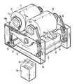
- 10 denotes a machine stand on which the two rolling mill rollers 11 and 12 are mounted.
- the axis 11a of the roller 11 is mounted directly in lugs 10a of the machine stand 10 on both sides: this roller is therefore referred to as the fixed roller.
- the axis 12a of the In contrast, roller 12 is supported on both sides on rockers 14 which can be pivoted relative to the machine stand 10; the roller 12 is therefore referred to as an adjusting roller.
- the rockers 14 in turn are pivotally mounted on stub axles 15 of the machine stand 10 and are designed in the manner of a two-arm lever.
- the free end of one lever arm is supported by a spindle lifting element 16, the free end of the other lever arm by a hydraulic piston-cylinder unit 17.
- the axis 12a of the adjusting roller 12 is also mounted on the rockers.
- a lathe movable on the machine stand 10 is indicated for turning off the adjusting roller 12.
- 19 designates a hydraulic unit with pumps, display elements and control buttons 20.
- the rockers 14 are loaded by the piston-cylinder units 17 in the upward direction, with a hydraulic pressure predetermined by the hydraulic unit 19.
- the height of the spindle lifting elements 16 can be adjusted separately, either manually or by motor.
- the height of the elements 16 defines the width of the roll gap a, the gap being wider the higher the elements 16 are set. Because the two spindle lifting elements 16 are separately adjustable, the parallelism of the roller gap a over the entire roller width b can also be ensured if, for example, one of the rollers has been turned non-parallel, for example the roller 12 by the lathe 18.
- the hydraulic pressure in the piston-cylinder units 17 is dimensioned such that, in normal operation, the rockers 14 are pressed firmly against the spindle lifting elements 16, but when a hard foreign body penetrates into the roll gap, the back pressure caused by this foreign body overcomes the hydraulic pressure of the elements 17 , with the result of an opening of the roller gap (protection of the hard roller surface). As soon as the stranger the body has "failed" downwards, the nip closes again automatically to its set value.
- the adjustment of the roll gap can obviously be carried out manually or by motor without having to stop the rolling mill.
Landscapes
- Engineering & Computer Science (AREA)
- Mechanical Engineering (AREA)
- Manufacturing & Machinery (AREA)
- Chemical & Material Sciences (AREA)
- Ceramic Engineering (AREA)
- Rolls And Other Rotary Bodies (AREA)
- Reduction Rolling/Reduction Stand/Operation Of Reduction Machine (AREA)
- Crushing And Grinding (AREA)
Abstract
Description
Die Erfindung betrifft ein Walzwerk mit verstellbarem Walzenspalt für keramische Massen gemäß dem Oberbegriff des Patentanspruches 1. Solche Walzwerke sind seit vielen Jahren bekannt und in Benutzung.The invention relates to a rolling mill with an adjustable nip for ceramic masses according to the preamble of claim 1. Such rolling mills have been known and used for many years.
Ein Problem bei derartigen Walzwerken ist bis heute die exakte Einstellung und Fixierung des Walzenspalts. Infolge ungleichmäßiger Abnutzung der Walzenoberflächen und mögliches unparalleles Abdrehen der Walzen beim erforderlichen Glätten der Walzenoberflächen ist bei den bisherigen Walzwerken das Konstanthalten eines gleichmäßigen Walzenspaltes über die ganze Walzenbreite kaum erreichbar. Ferner kann bei den herkömmlichen Walzwerken eine Verstellung bzw. Fixierung des Walzenspaltes, wobei im allgemeinen von Hand einzusetzende oder auszutauschende Distanzstücke verwendet werden, nur im Stillstand des Walzwerks erfolgen.A problem with such rolling mills is the exact setting and fixing of the roll gap. As a result of uneven wear of the roller surfaces and possible non-parallel turning of the rollers when the roller surfaces have to be smoothed, it is hardly possible to maintain a constant nip across the entire width of the rollers in previous rolling mills. Furthermore, in the conventional rolling mills, an adjustment or fixation of the roll gap, generally using spacers to be inserted or exchanged by hand, can only take place when the rolling mill is at a standstill.
Aufgabe der vorliegenden Erfindung ist es deshalb, die bekannten Walzwerke so auszugestalten, daß eine exakte Einstellung und Fixierung des Walzenspalts über die gesamte Walzenbreite ermöglich ist, und zwar auf einfache und schnelle Weise und auch bei laufendem Walzwerk. Die Lösung dieser Aufgabe ergibt sich aus den kennzeichnenden Merkmalen des Patentanspruches 1.The object of the present invention is therefore to design the known rolling mills in such a way that an exact setting and fixing of the nip is possible over the entire width of the roller, in a simple and quick manner and also when the rolling mill is running. The solution to this problem results from the characterizing features of patent claim 1.
Auf der Zeichnung ist eine Ausführungsform der Erfindung beispielsweise dargestellt, und zwar zeigt die einzige Figur eine Schemaskizze des Walzwerks in perspektivischer Darstellung.In the drawing, an embodiment of the invention is shown, for example, and that the single figure shows a schematic diagram of the rolling mill in perspective.
Auf der Zeichnung ist mit 10 ein Maschinenständer bezeichnet, auf dem die beiden Walzwerkswalzen 11 und 12 gelagert sind. Dabei ist die Achse 11a der Walze 11 unmittelbar in beidseitigen Ansätzen 10a des Maschinenständers 10 gelagert: diese Walze wird deshalb als die feste Walze bezeichnet. Die Achse 12a der Walze 12 ist dagegen beidseits an Schwingen 14 gelagert, die gegenüber dem Maschinenständer 10 verschwenkbar sind; die Walze 12 wird deshalb als Verstellwalze bezeichnet. Die Schwingen 14 ihrerseits sind schwenkbar an Achsstummeln 15 des Maschinenständers 10 gelagert und in Art eines Zweiarmhebels ausgebildet. Das freie Ende des einen Hebelarms ist durch ein Spindelhubelement 16 abgestützt, das freie Ende des anderen Hebelarms durch eine hydraulische Kolben-Zylinder-Einheit 17. An dem durch die Einheit 17 abgestützten Hebelarm ist auch die Achse 12a der Verstellwalze 12 an den Schwingen gelagert. Bei 18 ist eine auf dem Maschinenständer 10 verfahrbare Drehmaschine zum Abdrehen der Verstellwalze 12 angedeutet. Mit 19 schließlich ist ein Hydraulik-Aggregat mit Pumpen, Anzeigeelemente und Regelknöpfen 20 bezeichnet.In the drawing, 10 denotes a machine stand on which the two
Die Schwingen 14 werden durch die Kolben-Zylindereinheiten 17 in Richtung nach oben belastet, und zwar mit einem vom Hydraulikaggregat 19 aus vorgegebenen hydraulischen Druck. Damit drükken die entgegengesetzten Hebelarme der Schwingen 14 in Richtung von oben nach unten auf die Spindelhubelemente 16, die unnachgiebige Anschläge darstellen. Die Spindelhubelemente 16 können gesondert in ihrer Höhe verstellt werden, und zwar manuell oder motorisch. Die Höhe der Elemente 16 legt die Breite des Walzenspaltes a fest, wobei der Spalt umso breiter ist, je höher die Elemente 16 eingestellt sind. Dadurch, daß die beiden Spindelhubelemente 16 gesondert verstellbar sind, kann die Parallelität des Walzenspaltes a über die gesamte Walzenbreite b auch dann gewährleistet werden, wenn beispielsweise eine der Walzen unparallel abgedreht worden ist, beispielsweise die Walze 12 durch die Drehmaschine 18.The
Der hydraulische Druck in den Kolben-Zylinder-Einheiten 17 wird so bemessen, daß im Normalbetrieb die Schwingen 14 fest gegen die Spindelhubelemente 16 gepreßt werden, bei Eindringen eines überharten Fremdkörpers in den Walzenspalt jedoch der durch diesen Fremdkörper bewirkte Gegendruck den Hydraulikdruck der Elemente 17 überwindet, mit der Folge einer Öffnung des Walzenspalts (Schutz der harten Walzenoberfläche). Sobald der Fremd körper nach unten "durchgefallen" ist, schließt sich der Walzenspalt wieder selbsttätig auf seinen eingestellten Wert.The hydraulic pressure in the piston-
Die Verstellung des Walzenspaltes kann offensichtlich manuell oder motorisch durchgeführt werden, ohne das Walzwerk anhalten zu müssen.The adjustment of the roll gap can obviously be carried out manually or by motor without having to stop the rolling mill.
Selbstverständlich ist die Erfindung nicht auf das dargestellte Ausführungsbeispiel beschränkt, sondern es sind diesem gegenüber zahlreiche Abwandlungen möglich, ohne den Bereich der Erfindung zu verlassen. Dies gilt insbesondere für die Geometrie der Lagerschwingen und die Ausbildung der Spindelhubelemente und der Kolben-Zylinder-Einheiten sowie der Steuerelemente für deren Verstellung.Of course, the invention is not restricted to the exemplary embodiment shown, but numerous modifications are possible without departing from the scope of the invention. This applies in particular to the geometry of the bearing rockers and the design of the spindle lifting elements and the piston-cylinder units and the control elements for their adjustment.
Claims (6)
Applications Claiming Priority (2)
| Application Number | Priority Date | Filing Date | Title |
|---|---|---|---|
| DE3818540 | 1988-05-31 | ||
| DE19883818540 DE3818540A1 (en) | 1988-05-31 | 1988-05-31 | ROLLING MILL WITH ADJUSTABLE ROLLER NECK FOR CERAMIC MEASURES |
Publications (2)
| Publication Number | Publication Date |
|---|---|
| EP0344410A2 true EP0344410A2 (en) | 1989-12-06 |
| EP0344410A3 EP0344410A3 (en) | 1991-04-17 |
Family
ID=6355542
Family Applications (1)
| Application Number | Title | Priority Date | Filing Date |
|---|---|---|---|
| EP19890103998 Withdrawn EP0344410A3 (en) | 1988-05-31 | 1989-03-07 | Roll mill with an adjustable roll nip for ceramic masses |
Country Status (2)
| Country | Link |
|---|---|
| EP (1) | EP0344410A3 (en) |
| DE (1) | DE3818540A1 (en) |
Cited By (2)
| Publication number | Priority date | Publication date | Assignee | Title |
|---|---|---|---|---|
| DE4435935A1 (en) * | 1994-10-07 | 1996-04-11 | Rieter Werke Haendle | Roll mill with adjustment of roll gap width |
| WO2014116157A1 (en) * | 2013-01-28 | 2014-07-31 | Oneday Wall Ab | Machine and manufacturing method for building board |
Families Citing this family (5)
| Publication number | Priority date | Publication date | Assignee | Title |
|---|---|---|---|---|
| DE4121882A1 (en) * | 1991-07-02 | 1993-01-28 | Neumann Bruno Dipl Ing | Ceramic mass roller mill - has rocker or lever system to adjust and set setting and counter rollers |
| BE1027984B1 (en) * | 2020-01-14 | 2021-08-16 | Thyssenkrupp Ind Solutions Ag | Apparatus and method for grinding feedstock and control / regulating device and use |
| PE20221431A1 (en) | 2020-01-14 | 2022-09-21 | Thyssenkrupp Ind Solutions Ag | DEVICE AND PROCEDURE FOR THE GRINDING OF FEED MATERIAL |
| BE1027983B1 (en) * | 2020-01-14 | 2021-08-16 | Thyssenkrupp Ag | Apparatus and method for grinding feedstock and control / regulating device and use |
| BE1027987B1 (en) * | 2020-01-14 | 2021-08-16 | Thyssenkrupp Ag | Apparatus and method for grinding feedstock and control / regulating device and use |
Family Cites Families (10)
| Publication number | Priority date | Publication date | Assignee | Title |
|---|---|---|---|---|
| DE1004458B (en) * | 1953-06-09 | 1957-03-14 | Koppers Gmbh Heinrich | Roller mill |
| DE28476C (en) * | 1965-04-30 | H. bauermeister in Hamburg | Device for adjusting the rollers of roller mills during operation | |
| DE2045740A1 (en) * | 1970-09-16 | 1972-03-23 | J.M. Voith GmbH Maschinenfabrik, 7920 Heidenheim | Device for the exact parallel juxtaposition of two long machine parts, in particular press rolls |
| IT1057622B (en) * | 1976-02-25 | 1982-03-30 | Morando Spa Off | ROLLING MACHINE FOR CLAY AND SIMILAR |
| DE2704243A1 (en) * | 1977-02-02 | 1978-08-03 | Kloeckner Humboldt Deutz Ag | ROLLER MILL |
| DE2744990C3 (en) * | 1977-10-06 | 1980-07-17 | Kuesters, Eduard, 4150 Krefeld | Calender for pressure treatment of webs |
| IT1147385B (en) * | 1981-07-16 | 1986-11-19 | Giacomo Ferrero | CYLINDRIA OR CYLINDER MILL WITH HYDRAULIC ADJUSTMENT AND SAFETY |
| DE3308417A1 (en) * | 1982-03-20 | 1983-09-22 | Henry Simon Ltd., Stockport, Cheshire | Roller mill |
| US4519757A (en) * | 1984-01-17 | 1985-05-28 | Magna-Graphics Corporation | Web surface treating apparatus |
| US4810179A (en) * | 1988-01-27 | 1989-03-07 | Marshall & Williams Company | Force indicator for casting machines |
-
1988
- 1988-05-31 DE DE19883818540 patent/DE3818540A1/en not_active Withdrawn
-
1989
- 1989-03-07 EP EP19890103998 patent/EP0344410A3/en not_active Withdrawn
Cited By (6)
| Publication number | Priority date | Publication date | Assignee | Title |
|---|---|---|---|---|
| DE4435935A1 (en) * | 1994-10-07 | 1996-04-11 | Rieter Werke Haendle | Roll mill with adjustment of roll gap width |
| DE4435935C3 (en) * | 1994-10-07 | 2003-11-06 | Rieter Werke Haendle | Method of adjusting the nip of a rolling mill and rolling mill |
| WO2014116157A1 (en) * | 2013-01-28 | 2014-07-31 | Oneday Wall Ab | Machine and manufacturing method for building board |
| US9694566B2 (en) | 2013-01-28 | 2017-07-04 | Oneday Wall Ab | Machine and manufacturing method for building board |
| RU2637677C2 (en) * | 2013-01-28 | 2017-12-06 | Уандей Уолл Аб | Machine and method of manufacturing construction panel |
| US10189234B2 (en) | 2013-01-28 | 2019-01-29 | Oneday Wall Ab | Machine and manufacturing method for building board |
Also Published As
| Publication number | Publication date |
|---|---|
| EP0344410A3 (en) | 1991-04-17 |
| DE3818540A1 (en) | 1989-12-07 |
Similar Documents
| Publication | Publication Date | Title |
|---|---|---|
| DE2760350C2 (en) | ||
| DE2912458C2 (en) | ||
| DE29902366U1 (en) | Foam sponge cutting machine with vertical cutting wire | |
| DE69315337T2 (en) | MACHINE FOR CUTTING SHEETS FROM A PAPER TRACK AND AT THE SAME TIME CUTTING A CROSS STRIP | |
| EP0252418A1 (en) | Guillotine-type cutter | |
| DE3207622A1 (en) | DEVICE FOR TURNING ON, OFF AND ADJUSTING APPLICATION ROLLERS ON THE PLATE CYLINDER OF PRINTING MACHINES | |
| DE1950555B2 (en) | Device for treating, in particular coating, web-shaped material in an adjustable roller gap | |
| EP0386520A2 (en) | Material bed roller mill | |
| EP0344410A2 (en) | Roll mill with an adjustable roll nip for ceramic masses | |
| DE2948842C2 (en) | Pull-up section | |
| DE3016785C2 (en) | Hydraulic multi-rolling mill | |
| EP0255714A2 (en) | Multiple-roll rolling mill stand with shiftable intermediary rolls having tapered ends | |
| DE2127757B2 (en) | Missing sheet scanning and control device | |
| DE1602184B2 (en) | Multi-roll stand arrangement | |
| DE2932115A1 (en) | Straightening machine for metal sheets etc. - has individual synchronised supports for straightening rollers | |
| DE2330824A1 (en) | Roller mill for grinding pastes e.g. dyestuffs - has integral roller-support frame | |
| DE3012852C2 (en) | Supercalender | |
| DE633933C (en) | Adjusting device on roller mills for pasty goods | |
| DE226327C (en) | ||
| DE3048280A1 (en) | Universal rolling machine - in which housing can be moved integrally with horizontal and vertical roll to control dimensions of H=section workpieces etc. | |
| DE340045C (en) | Grist, grinding and crushing mills | |
| DE1234661B (en) | Roller straightening machine for straightening metal plates and strips | |
| DE234046C (en) | ||
| DE476271C (en) | Device for changing the paper rolls in printing machines, in particular rotary printing machines | |
| DE3308417A1 (en) | Roller mill |
Legal Events
| Date | Code | Title | Description |
|---|---|---|---|
| PUAI | Public reference made under article 153(3) epc to a published international application that has entered the european phase |
Free format text: ORIGINAL CODE: 0009012 |
|
| AK | Designated contracting states |
Kind code of ref document: A2 Designated state(s): DE ES FR GB IT |
|
| PUAL | Search report despatched |
Free format text: ORIGINAL CODE: 0009013 |
|
| AK | Designated contracting states |
Kind code of ref document: A3 Designated state(s): DE ES FR GB IT |
|
| 17P | Request for examination filed |
Effective date: 19910523 |
|
| 17Q | First examination report despatched |
Effective date: 19911004 |
|
| STAA | Information on the status of an ep patent application or granted ep patent |
Free format text: STATUS: THE APPLICATION HAS BEEN WITHDRAWN |
|
| 18W | Application withdrawn |
Withdrawal date: 19920717 |