EP0344020B1 - Verfahren zum Herstellen eines Blechpaketes mit geschrägten Leiternuten und ein nach diesem Verfahren hergestelltes magnetisches Element - Google Patents
Verfahren zum Herstellen eines Blechpaketes mit geschrägten Leiternuten und ein nach diesem Verfahren hergestelltes magnetisches Element Download PDFInfo
- Publication number
- EP0344020B1 EP0344020B1 EP89305394A EP89305394A EP0344020B1 EP 0344020 B1 EP0344020 B1 EP 0344020B1 EP 89305394 A EP89305394 A EP 89305394A EP 89305394 A EP89305394 A EP 89305394A EP 0344020 B1 EP0344020 B1 EP 0344020B1
- Authority
- EP
- European Patent Office
- Prior art keywords
- stacking
- lamellae
- donut
- stack
- stator
- Prior art date
- Legal status (The legal status is an assumption and is not a legal conclusion. Google has not performed a legal analysis and makes no representation as to the accuracy of the status listed.)
- Expired - Lifetime
Links
- 238000000034 method Methods 0.000 title claims description 23
- 239000004020 conductor Substances 0.000 title description 23
- 238000003475 lamination Methods 0.000 title description 13
- 238000004519 manufacturing process Methods 0.000 title description 2
- 235000012489 doughnuts Nutrition 0.000 claims description 10
- 239000002184 metal Substances 0.000 claims description 8
- 238000003754 machining Methods 0.000 claims description 7
- 230000013011 mating Effects 0.000 claims description 3
- 230000006835 compression Effects 0.000 description 17
- 238000007906 compression Methods 0.000 description 17
- VYPSYNLAJGMNEJ-UHFFFAOYSA-N Silicium dioxide Chemical compound O=[Si]=O VYPSYNLAJGMNEJ-UHFFFAOYSA-N 0.000 description 4
- 239000000463 material Substances 0.000 description 3
- 239000007787 solid Substances 0.000 description 3
- 229910000831 Steel Inorganic materials 0.000 description 2
- 239000000377 silicon dioxide Substances 0.000 description 2
- 239000010959 steel Substances 0.000 description 2
- 239000004593 Epoxy Substances 0.000 description 1
- 230000004323 axial length Effects 0.000 description 1
- 230000015556 catabolic process Effects 0.000 description 1
- 238000006731 degradation reaction Methods 0.000 description 1
- 230000004907 flux Effects 0.000 description 1
- -1 for example Substances 0.000 description 1
- 238000009434 installation Methods 0.000 description 1
- 239000000696 magnetic material Substances 0.000 description 1
Images


Classifications
-
- B—PERFORMING OPERATIONS; TRANSPORTING
- B32—LAYERED PRODUCTS
- B32B—LAYERED PRODUCTS, i.e. PRODUCTS BUILT-UP OF STRATA OF FLAT OR NON-FLAT, e.g. CELLULAR OR HONEYCOMB, FORM
- B32B5/00—Layered products characterised by the non- homogeneity or physical structure, i.e. comprising a fibrous, filamentary, particulate or foam layer; Layered products characterised by having a layer differing constitutionally or physically in different parts
-
- H—ELECTRICITY
- H02—GENERATION; CONVERSION OR DISTRIBUTION OF ELECTRIC POWER
- H02K—DYNAMO-ELECTRIC MACHINES
- H02K15/00—Processes or apparatus specially adapted for manufacturing, assembling, maintaining or repairing of dynamo-electric machines
- H02K15/02—Processes or apparatus specially adapted for manufacturing, assembling, maintaining or repairing of dynamo-electric machines of stator or rotor bodies
- H02K15/021—Magnetic cores
-
- H—ELECTRICITY
- H02—GENERATION; CONVERSION OR DISTRIBUTION OF ELECTRIC POWER
- H02K—DYNAMO-ELECTRIC MACHINES
- H02K2201/00—Specific aspects not provided for in the other groups of this subclass relating to the magnetic circuits
- H02K2201/06—Magnetic cores, or permanent magnets characterised by their skew
-
- Y—GENERAL TAGGING OF NEW TECHNOLOGICAL DEVELOPMENTS; GENERAL TAGGING OF CROSS-SECTIONAL TECHNOLOGIES SPANNING OVER SEVERAL SECTIONS OF THE IPC; TECHNICAL SUBJECTS COVERED BY FORMER USPC CROSS-REFERENCE ART COLLECTIONS [XRACs] AND DIGESTS
- Y10—TECHNICAL SUBJECTS COVERED BY FORMER USPC
- Y10T—TECHNICAL SUBJECTS COVERED BY FORMER US CLASSIFICATION
- Y10T29/00—Metal working
- Y10T29/49—Method of mechanical manufacture
- Y10T29/49002—Electrical device making
- Y10T29/49009—Dynamoelectric machine
- Y10T29/49012—Rotor
-
- Y—GENERAL TAGGING OF NEW TECHNOLOGICAL DEVELOPMENTS; GENERAL TAGGING OF CROSS-SECTIONAL TECHNOLOGIES SPANNING OVER SEVERAL SECTIONS OF THE IPC; TECHNICAL SUBJECTS COVERED BY FORMER USPC CROSS-REFERENCE ART COLLECTIONS [XRACs] AND DIGESTS
- Y10—TECHNICAL SUBJECTS COVERED BY FORMER USPC
- Y10T—TECHNICAL SUBJECTS COVERED BY FORMER US CLASSIFICATION
- Y10T29/00—Metal working
- Y10T29/53—Means to assemble or disassemble
- Y10T29/5313—Means to assemble electrical device
- Y10T29/5317—Laminated device
Definitions
- the present invention relates to dynamoelectric machines and, more particularly, to dynamoelectric machines wherein one of the elements is formed by stacking a plurality of lamellae of a magnetic metal.
- the present invention may be employed to form a stationary or rotating member of a dynamoelectric machine, for concreteness of description, the following description is directed toward the assembly of an annular stator of a large generator.
- the problems associated with the assembly of corresponding elements of a motor are so similar that one skilled in the art with the present disclosure for reference would be fully enabled to apply the present invention to such apparatus.
- a stator is conventionally built up by stacking a plurality of thin (0,3542 mm ; 0.014 inch) lamellae of a high-resistance magnetic material such as, for example, silica steel.
- Such stacking is conventionally aided by one or more dovetail-shaped key bars affixed inside a stator frame for engaging dovetail-shaped slots in the individual lamellae.
- the dovetail slots of the lamellae are fitted onto the dovetail-shaped key bars.
- an axial compressive force is applied to the ends of the stack and maintained for a substantial time to compress the lamellae into a rigid assembly.
- dovetail-shaped engaging elements instead of dovetail-shaped engaging elements, it is within contemplation to employ one or more tabs extending radially outward from the outer perimeter thereof.
- One or more bars affixed to the stator frame each includes a slot therein for engagement with the tabs extending from the lamellae.
- the guiding members key bars or slotted bars
- the guiding members are skewed with respect to the axis of the stator. Up to about four degrees of skew, the differences between compression and guidance angles can be accommodated by manufacturing tolerances and deformation of material to attain satisfactory assembly. At skew angles exceeding about four degrees, the difference between the angle of applied compression force (axial) and the angle of lamellae guidance (skewed) results in the lamellae hanging up on the key bars or slotted bars. Due to such hanging up (binding), it is not possible to attain sufficient compression on the lamellae to produce a substantially rigid stator stack.
- AT-A-220701 an arrangement for forming slots in stators or rotors with a skew angle relatively to the axis by forming the laminated plates into packets and then fixing the packets next to one another in a row with the slots formed in each packet being aligned in such a way as to approximate to the desired helical curve.
- this does not overcome the problem of lamellae hanging up on keybars.
- the present invention provides a method for forming a laminated member of a dynamoelectric machine comprising providing a stacking guide having a skew angle; stacking lamellae of a magnetic metal on said stacking guide to form a stack, whereby said lamellae are given a skew equal to said skew angle; securing said stack against movement; machining guide elements in an exterior surface of said stack; and installing said stack in a frame upon guide members mating with said guide elements.
- the present invention provides a laminated member of a dynamoelectric machine which is preassembled using guidance members.
- the guidance members are disposed at a skew angle with respect to a central axis of the stator.
- the outer perimeter of the preassembled stator is then machined to form guidance elements disposed parallel to a central axis of the stator.
- the preassembled elements are mounted in a frame on further guidance elements disposed parallel to the central axis of the stator.
- axial compression forces act parallel to guidance forces, whereby hanging up is avoided.
- a method for forming a stator of a dynamoelectric machine comprising: providing a stacking guide having a skew angle, stacking lamellae of a magnetic metal on the stacking guide to form a stack, whereby the lamellae are given a skew equal to the skew angle, securing the stack against movement, machining guide elements in an exterior surface of the stack, and installing the stack in a stator frame upon guide members mating with the guide elements.
- a stator 10 is built up as an annular stack of lamination segments 12.
- Each lamination segment 12 is a thin (e.g. about 0.014 inch of 0.35 mm) lamellae of a high- resistivity magnetic metal, conventionally silica steel.
- Each lamellae is electrically insulated from its upper and lower neighbors, in order to force any eddy currents induced therein to flow in a relatively long path within lamination segment 12.
- a plurality of key bars 14 are disposed within a stator frame (not otherwise shown). Each key bar 14 includes a dovetail portion 16 upon which a dovetail slot 18 in the outer perimeter of lamination segment 12 is fitted. Each lamination segment 12 includes a plurality of conductor slots 20 in its inner edge.
- the number of lamination segments 12 making up a layer may vary from machine to machine. Common numbers include six and twelve. Similarly, the number of key bars 14 and conductor slots 20 may also vary. Such variations are not of concern to the present invention.
- the embodiment used in the present disclosure is illustrative only, and should not be seen as limiting the invention.
- lamination segment 12 is shown with key bars 14 (Fig. 1) omitted to reveal elements necessary to the description.
- key bars 14 Fig. 1
- layers of lamination segments 12 are placed in the growing stack forming stator 10 until several centimeters of depth is attained. Then, a bonding material such as, for example, an epoxy, is applied and a compression force is applied to the portion of the stack then existing.
- compression force is maintained for a substantial time until the bonding material is set or cured. Then, stacking is resumed.
- Compression forces may be applied, for example, using first and second end plates 22 and 24 with a plurality of rods 26 passing therebetween. Each rod 26 engages a nut 28 which tends to apply a compression force in an axial direction as indicated by a force arrow 30. Due to the skewing of the key bars 14, guidance forces are also skewed as indicated by a skewed guidance arrow 32. The angle between force arrow 30 and skewed guidance arrow 32 is the skew angle of dovetail slots 18 and conductor slots 20.
- a central mandrel 36 includes a plurality of skewed protuberances 38 having a skew angle with respect to a central axis of mandrel 36 equal to the desired skew angle of conductor slots 20.
- a bottom plate 40 supports lamination segments 12 as they are laid in place in stacking fixture 34.
- An outer guide circle 42 defines an outer diameter of a donut or packet 44. Guided by skewed protuberances 38, packet 44 is built up with conductor slots 20 following the skew angle of skewed protuberance 38.
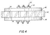
- a packet 44 is shown compressed between first and second pressure plates 48 and 50 by a plurality of bolts 50 onto which corresponding nuts 52 are tightened.
- dovetail slots 18 are machined in the perimeter of packet 44.
- packet 44 is released from pressure plates 46 and 48 and packet 44 is assembled onto key bars 14 (Fig. 1) which are disposed parallel to the central axis of stator 10. It will be evident that, when an axial compression force is applied to a stator 10 formed of a plurality of packets 44, the compression force and guidance forces are parallel to each other. As a consequence, the problems arising from dovetail slots 18 hanging up on dovetail portions 16 are eliminated.
- packet 44 is bonded during compression to form a unitary assembly. Then, during assembly of stator 10, a plurality of packets 44 are stacked end to end. In one embodiment of the invention, each packet 44 has an axial length of about 5.08 cm (two inches). Thus, each packet 44 contains about 70 layers of lamination segments 12. To build a stator 10 of, for example, 70.84 cm (28 inches), requires installation of 14 packets 44. This leaves only 13 inter-packet interfaces to be bonded during final compression and bonding in stator 10. Since the compression and guidance forces are parallel to each other, no problem with hanging up is expected.
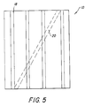
- stator 10 is shown in Fig. 5, wherein dovetail portions 18 are parallel to the central axis of stator 10, while conductor slots 20 (only one of which is shown) are skewed at whatever skew angle is desired.
- packet 44 may remain unbonded at that time. While being held together by pressure plates 46 and 48 (or any corresponding means), dovetail slots 18 are machined therein. Then, the unbonded stack may be installed on key bars 14 for final compression and bonding during stacking of stator 10. In this technique, hanging up is also not a problem. Accordingly, a tight, unitary stator 10 can be formed.
- a technique for aligning dovetail slots 18 and conductor slots 20 in succeeding packets 44 would occur to one skilled in the art.
- a dummy bar, skewed at the desired skew angle is engaged in a conductor slot 20 of a completed packet 44 and in a conductor slot 20 of a packet 44 in which it is desired to machine dovetail slots 18.
- dovetail slots 18 are machined in the new packet 44 as continuations of the dovetail slots 18 in the completed packet 44.
- Other techniques would occur to one skilled in the art.
- each lamination segment 12 may include an outward-directed tab (not shown) for engagement with a skewed slot (not shown) in outer guide circle 42. Once the desired skewed alignment is attained, and packet 44 is clamped together, the tabs may be machined off, either before or after dovetail slots 18 are machined in the outer perimeter of stator 10. As a further alternative, a single slot (not shown) may be formed in each lamination segment 12 prior to initial assembly of packet 44.
- a plurality of skewed bars (not shown) affixed to outer guide circle 42 may be substituted for skewed protuberances 38 shown affixed to mandrel 36 in Fig. 3.
- slots used for assembly remain in the outer perimeter of packet 44, and thus this embodiment may not be preferred.
Landscapes
- Engineering & Computer Science (AREA)
- Manufacturing & Machinery (AREA)
- Power Engineering (AREA)
- Iron Core Of Rotating Electric Machines (AREA)
- Manufacture Of Motors, Generators (AREA)
Claims (9)
- Verfahren zum Herstellen eines geblechten Teils von einer dynamoelektrischen Maschine, enthaltend:
Bereitstellen einer Stapelführung (34) mit einem Schrägwinkel,
Stapeln von Blechen (12) aus einem magnetischen Metall auf der Stapelführung zur Herstellung eines Stapels (44), wobei den Blechen eine Schrägstellung gegeben wird, die gleich dem Schrägwinkel ist,
Befestigen des Stapels gegen Bewegung,
maschinelle Herstellung von Führungselementen (18) in einer Außenfläche des Stapels und
Anbringen des Stapels in einem Rahmen auf Führungsteilen (14), die mit den Führungselementen zusammenpassen. - Verfahren nach Anspruch 1, wobei in dem maschinellen Herstellungsschritt die Führungselemente im wesentlichen parallel zu einer Mittelachse des geblechten Teils hergestellt werden.
- Verfahren nach Anspruch 1, enthaltend:
Stapeln von weniger als allen Blechen zur Herstellung einer ersten Ringröhre,
maschinelle Herstellung der Führungselemente in der ersten Ringröhre,
Stapeln einer zusätzlichen Anzahl der Bleche zur Herstellung wenigstens einer zweiten Ringröhre,
maschinelle Herstellung der Führungselemente in der zweiten Ringröhre,
Anbringen der ersten Ringröhre in dem Rahmen,
Anbringen der wenigstens zweiten Ringröhre in dem Rahmen und
Zusammenpressen und Verbinden der ersten und der wenigstens zweiten Ringröhre in dem Rahmen zur Herstellung des geblechten Teils. - Verfahren nach Anspruch 3, wobei die Stapelschritte das Verbinden der ersten Ringröhre und das Verbinden wenigstens einer zweiten Ringröhre beinhalten, bevor der Einbauschritt ausgeführt wird.
- Verfahren nach Anspruch 1, enthaltend:
Herstellen wenigstens einer Nut (20) in einem inneren Rand von Jedem der Bleche,
Bereitstellen einer Stapelführung mit wenigstens einem schräg verlaufenden Vorsprung (38), auf den die wenigstens eine Nut aufgepaßt werden kann,
und Stapeln der Bleche, wobei die wenigstens eine Nut an dem wenigstens einen Vorsprung angreift, wodurch dem Stapel die Schrägstellung gegeben wird. - Verfahren nach Anspruch 1, wobei der Stapelschritt das Stapeln der Bleche zur Herstellung eines vollständigen geblechten Teils beinhaltet.
- Verfahren nach Anspruch 1, wobei:
die Führungselemente schwalbenschwanzförmige Nuten in einem Außenrand von jedem der Bleche aufweisen und
die Führungsteile Keilstäbe mit schwalbenschwanzförmigen Abschnitten aufweisen, die mit den schwalbenschwanzförmigen Nuten zusammenpaßbar sind. - Verfahren nach einem der vorstehenden Ansprüche, wobei das geblechte Teil ein Stator (10) ist.
- Verfahren nach einem der Ansprüche 1 bis 7, wobei das geblechte Teil ein Rotor ist.
Applications Claiming Priority (2)
| Application Number | Priority Date | Filing Date | Title |
|---|---|---|---|
| US07/199,645 US4854034A (en) | 1988-05-27 | 1988-05-27 | Method for producing a stack of laminations with skewed conductor slots |
| US199645 | 1998-11-25 |
Publications (3)
| Publication Number | Publication Date |
|---|---|
| EP0344020A2 EP0344020A2 (de) | 1989-11-29 |
| EP0344020A3 EP0344020A3 (en) | 1990-06-27 |
| EP0344020B1 true EP0344020B1 (de) | 1993-11-03 |
Family
ID=22738428
Family Applications (1)
| Application Number | Title | Priority Date | Filing Date |
|---|---|---|---|
| EP89305394A Expired - Lifetime EP0344020B1 (de) | 1988-05-27 | 1989-05-26 | Verfahren zum Herstellen eines Blechpaketes mit geschrägten Leiternuten und ein nach diesem Verfahren hergestelltes magnetisches Element |
Country Status (6)
| Country | Link |
|---|---|
| US (1) | US4854034A (de) |
| EP (1) | EP0344020B1 (de) |
| JP (1) | JPH02146940A (de) |
| KR (1) | KR890017077A (de) |
| CN (1) | CN1038190A (de) |
| DE (1) | DE68910384T2 (de) |
Families Citing this family (16)
| Publication number | Priority date | Publication date | Assignee | Title |
|---|---|---|---|---|
| FI90604C (fi) * | 1991-02-07 | 1994-02-25 | Kone Oy | Epätahtimoottori ja menetelmä epätahtimoottorin staattorin ja/tai roottorin valmistamiseksi |
| GB2310545B (en) * | 1996-02-22 | 2000-04-19 | Honda Motor Co Ltd | Stator core and method and apparatus for assembling same |
| ITPN960017A1 (it) * | 1996-03-12 | 1997-09-12 | Sole Spa | Macchina elettrica, in particolare motore elettrico |
| RU2171532C1 (ru) * | 2000-12-15 | 2001-07-27 | ООО "КД-Электро" | Способ изготовления пакетов листов ротора электрической машины и приспособление для шихтовки и запрессовки пакета листов ротора электрической машины |
| ITTO20030421A1 (it) * | 2003-06-05 | 2004-12-06 | Varian Spa | Pompa da vuoto compatta |
| JP2005103638A (ja) * | 2003-09-10 | 2005-04-21 | Aisin Aw Co Ltd | モータ用積層コアの製造方法、その製造装置、及び積層治具 |
| JP2005278298A (ja) * | 2004-03-24 | 2005-10-06 | Yaskawa Electric Corp | 分割コア、スキュー付き分割積層コア、スキュー付き積層環状コア、分割積層コアスキュー形成装置、固定子、および電動機 |
| JP2005335536A (ja) * | 2004-05-27 | 2005-12-08 | Sanyo Electric Co Ltd | 電動車輪用ハブユニット及び該ハブユニットを具えた乗物 |
| JP2006333581A (ja) * | 2005-05-24 | 2006-12-07 | Toyota Industries Corp | ステータ及びステータの製造方法 |
| US7861404B2 (en) * | 2006-10-19 | 2011-01-04 | Siemens Energy, Inc. | Method for removing the endplate of an electric generator |
| US8643246B2 (en) * | 2011-06-28 | 2014-02-04 | Siemens Energy, Inc. | Stator core module, stator core assembly and process for assembling a stator core assembly |
| KR20180041672A (ko) * | 2015-08-19 | 2018-04-24 | 티엠4 인코포레이티드 | 전기 기계용 주조 냉각 장치 |
| JP6610494B2 (ja) * | 2016-10-05 | 2019-11-27 | フジテック株式会社 | 固定子コアの製造方法、固定子コア製造装置及び固定子コア片 |
| DE102017011391A1 (de) * | 2017-12-11 | 2018-12-27 | Daimler Ag | Blechpaket für eine elektrische Maschine, insbesondere eines Kraftfahrzeugs, sowie Aktivteil für eine elektrische Maschine, insbesondere eines Kraftfahrzeugs |
| DE102020116383A1 (de) * | 2020-06-22 | 2021-12-23 | Valeo Siemens Eautomotive Germany Gmbh | Verfahren zur Herstellung eines geschrägten Stators |
| EP4024681A1 (de) * | 2020-12-30 | 2022-07-06 | Siemens Aktiengesellschaft | Verfahren zur fertigung eines stapels von magnetblechen für einen rotor und/oder stator einer elektrischen maschine sowie verfahren zur fertigung einer elektrischen maschine und verfahren zur fertigung einer anlage und eines fahrzeugs |
Family Cites Families (2)
| Publication number | Priority date | Publication date | Assignee | Title |
|---|---|---|---|---|
| US2424443A (en) * | 1944-12-06 | 1947-07-22 | Gen Electric | Dynamoelectric machine |
| AT220701B (de) * | 1961-03-01 | 1962-04-10 | Elin Union Ag | Einrichtung zur Rotor- oder Statorblechpaketbefestigung für elektrische Maschinen |
-
1988
- 1988-05-27 US US07/199,645 patent/US4854034A/en not_active Expired - Fee Related
-
1989
- 1989-04-14 CN CN89102384A patent/CN1038190A/zh active Pending
- 1989-05-26 DE DE89305394T patent/DE68910384T2/de not_active Expired - Fee Related
- 1989-05-26 JP JP1131720A patent/JPH02146940A/ja active Pending
- 1989-05-26 KR KR1019890007079A patent/KR890017077A/ko not_active Withdrawn
- 1989-05-26 EP EP89305394A patent/EP0344020B1/de not_active Expired - Lifetime
Non-Patent Citations (3)
| Title |
|---|
| PATENT ABSTRACTS OF JAPAN, vol. 11, no. 165 (E-510) 27 May 1987, & JP-A-61 295847 * |
| PATENT ABSTRACTS OF JAPAN, vol. 4, no. 87 (E-16) 21 June 1980, & JP-A-55 053157 * |
| PATENT ABSTRACTS OF JAPAN, vol. 7, no. 27 (E-156) 03 February 1983, & JP-A-57 183251 * |
Also Published As
| Publication number | Publication date |
|---|---|
| CN1038190A (zh) | 1989-12-20 |
| EP0344020A3 (en) | 1990-06-27 |
| US4854034A (en) | 1989-08-08 |
| DE68910384T2 (de) | 1994-04-28 |
| EP0344020A2 (de) | 1989-11-29 |
| DE68910384D1 (de) | 1993-12-09 |
| JPH02146940A (ja) | 1990-06-06 |
| KR890017077A (ko) | 1989-12-15 |
Similar Documents
| Publication | Publication Date | Title |
|---|---|---|
| EP0344020B1 (de) | Verfahren zum Herstellen eines Blechpaketes mit geschrägten Leiternuten und ein nach diesem Verfahren hergestelltes magnetisches Element | |
| US4564779A (en) | Dynamoelectric machine stator using cylindrical keybars | |
| EP1592107B1 (de) | Statorkernbaugruppe | |
| US5893205A (en) | Rotor for a reluctance machine, and method of making | |
| US9634548B2 (en) | Method for manufacturing an armature winding for an electric machine | |
| US6858965B2 (en) | Stator for a synchronous machine | |
| EP1865587B1 (de) | Magnetkern bestehend aus magnetischem Metallpulver für elektrische Maschinen | |
| JPH06205556A (ja) | 回転子巻線装置及び回転電動機械 | |
| CN112219339B (zh) | 用于旋转电机的定子 | |
| US4268772A (en) | Laminated rotor with cast end windings | |
| US4204314A (en) | Method of making cast windings for electric motors | |
| US5432391A (en) | Conformable dynamoelectric machine field distance blocks and methods of installation | |
| EP3477819B1 (de) | Verfahren zur herstellung eines stators und zahnstapel für einen stator | |
| CN111200321A (zh) | 旋转电机、定子及定子的组装方法 | |
| US4123678A (en) | Laminated stator core member secured only by bonding the windings | |
| EP2642646B1 (de) | Verfahren zur Herstellung eines Stators | |
| US4475052A (en) | Air gap winding rotating electric machine | |
| GB2139821A (en) | Modular motor construction | |
| GB2338350A (en) | Cooling laminated assemblies of electrical rotating machines | |
| CA1055095A (en) | Rotor with form wound coils for synchronous dynamoelectric machine | |
| JPH04372552A (ja) | 電動機の固定子用積層鉄心 | |
| US561590A (en) | Armature for dynamo-electric machines | |
| US10284059B2 (en) | Device for manufacturing a stator | |
| GB2123318A (en) | Stators for electric motors | |
| US20260081492A1 (en) | Lamination scallop and shaft knurl |
Legal Events
| Date | Code | Title | Description |
|---|---|---|---|
| PUAI | Public reference made under article 153(3) epc to a published international application that has entered the european phase |
Free format text: ORIGINAL CODE: 0009012 |
|
| AK | Designated contracting states |
Kind code of ref document: A2 Designated state(s): CH DE FR GB IT LI SE |
|
| PUAL | Search report despatched |
Free format text: ORIGINAL CODE: 0009013 |
|
| AK | Designated contracting states |
Kind code of ref document: A3 Designated state(s): CH DE FR GB IT LI SE |
|
| 17P | Request for examination filed |
Effective date: 19901122 |
|
| 17Q | First examination report despatched |
Effective date: 19920811 |
|
| GRAA | (expected) grant |
Free format text: ORIGINAL CODE: 0009210 |
|
| AK | Designated contracting states |
Kind code of ref document: B1 Designated state(s): CH DE FR GB IT LI SE |
|
| PG25 | Lapsed in a contracting state [announced via postgrant information from national office to epo] |
Ref country code: IT Free format text: LAPSE BECAUSE OF FAILURE TO SUBMIT A TRANSLATION OF THE DESCRIPTION OR TO PAY THE FEE WITHIN THE PRESCRIBED TIME-LIMIT;WARNING: LAPSES OF ITALIAN PATENTS WITH EFFECTIVE DATE BEFORE 2007 MAY HAVE OCCURRED AT ANY TIME BEFORE 2007. THE CORRECT EFFECTIVE DATE MAY BE DIFFERENT FROM THE ONE RECORDED. Effective date: 19931103 Ref country code: SE Effective date: 19931103 |
|
| ET | Fr: translation filed | ||
| REF | Corresponds to: |
Ref document number: 68910384 Country of ref document: DE Date of ref document: 19931209 |
|
| PG25 | Lapsed in a contracting state [announced via postgrant information from national office to epo] |
Ref country code: GB Effective date: 19940526 |
|
| PG25 | Lapsed in a contracting state [announced via postgrant information from national office to epo] |
Ref country code: CH Effective date: 19940531 Ref country code: LI Effective date: 19940531 |
|
| PLBE | No opposition filed within time limit |
Free format text: ORIGINAL CODE: 0009261 |
|
| STAA | Information on the status of an ep patent application or granted ep patent |
Free format text: STATUS: NO OPPOSITION FILED WITHIN TIME LIMIT |
|
| 26N | No opposition filed | ||
| GBPC | Gb: european patent ceased through non-payment of renewal fee |
Effective date: 19940526 |
|
| PG25 | Lapsed in a contracting state [announced via postgrant information from national office to epo] |
Ref country code: FR Effective date: 19950131 |
|
| REG | Reference to a national code |
Ref country code: CH Ref legal event code: PL |
|
| PG25 | Lapsed in a contracting state [announced via postgrant information from national office to epo] |
Ref country code: DE Effective date: 19950201 |
|
| REG | Reference to a national code |
Ref country code: FR Ref legal event code: ST |