EP0343630A2 - Durch Fernsteuerung rücksetzbare Endgerätvorrichtung - Google Patents
Durch Fernsteuerung rücksetzbare Endgerätvorrichtung Download PDFInfo
- Publication number
- EP0343630A2 EP0343630A2 EP89109387A EP89109387A EP0343630A2 EP 0343630 A2 EP0343630 A2 EP 0343630A2 EP 89109387 A EP89109387 A EP 89109387A EP 89109387 A EP89109387 A EP 89109387A EP 0343630 A2 EP0343630 A2 EP 0343630A2
- Authority
- EP
- European Patent Office
- Prior art keywords
- data
- reset
- command
- terminal apparatus
- detecting
- Prior art date
- Legal status (The legal status is an assumption and is not a legal conclusion. Google has not performed a legal analysis and makes no representation as to the accuracy of the status listed.)
- Withdrawn
Links
Images


Classifications
-
- H—ELECTRICITY
- H04—ELECTRIC COMMUNICATION TECHNIQUE
- H04L—TRANSMISSION OF DIGITAL INFORMATION, e.g. TELEGRAPHIC COMMUNICATION
- H04L12/00—Data switching networks
- H04L12/02—Details
- H04L12/12—Arrangements for remote connection or disconnection of substations or of equipment thereof
-
- Y—GENERAL TAGGING OF NEW TECHNOLOGICAL DEVELOPMENTS; GENERAL TAGGING OF CROSS-SECTIONAL TECHNOLOGIES SPANNING OVER SEVERAL SECTIONS OF THE IPC; TECHNICAL SUBJECTS COVERED BY FORMER USPC CROSS-REFERENCE ART COLLECTIONS [XRACs] AND DIGESTS
- Y02—TECHNOLOGIES OR APPLICATIONS FOR MITIGATION OR ADAPTATION AGAINST CLIMATE CHANGE
- Y02D—CLIMATE CHANGE MITIGATION TECHNOLOGIES IN INFORMATION AND COMMUNICATION TECHNOLOGIES [ICT], I.E. INFORMATION AND COMMUNICATION TECHNOLOGIES AIMING AT THE REDUCTION OF THEIR OWN ENERGY USE
- Y02D30/00—Reducing energy consumption in communication networks
- Y02D30/50—Reducing energy consumption in communication networks in wire-line communication networks, e.g. low power modes or reduced link rate
Definitions
- the present invention relates to a terminal apparatus used in a terminal station in a data communication system.
- the terminal apparatus according to the present invention is, in particular, applicable in an unmanned terminal station.
- Unmanned stations wherein data is collected and the collected data is sent to another station, are used, for example, in the following system: in a fire information network system for detecting and reporting an occurrence of a fire; in a fuel gas supplying system for monitoring a gas flow rate at a plurality of flow rate monitoring points; in an electric power supplying system for monitoring an operation at a dam, an electric transformer substation, or the like.
- Figures 1A and 1B each show a system wherein data is collected at each terminal station, and then is sent to a master station.
- reference numeral 11 denotes a master station
- 12-1 to 12-n each denote a terminal station
- 13 denotes a transmission line.
- reference numeral 21 denotes a master station
- 22 denotes a terminal station
- 23 denotes a transmission line.
- each terminal station collects data, and sometimes processes the collected data.
- the master station sends a command requesting data to the corresponding terminal station(s) through the transmission line.
- the terminal station sends the collected and processed data to the master station through the transmission line.
- the master station can monitor the data collected at all of the terminal stations in the system.
- the aforementioned fire information network system or the system for monitoring a gas flow rate correspond to the arrangement shown in Fig. 1A
- the aforementioned electric power supplying system wherein operations at a remote place are monitored at a master station corresponds to the arrangement shown in Fig. 1B.
- Figure 2 shows a conventional arrangement for resetting and restarting a terminal station by a master station.
- reference numeral 31 denotes an apparatus of a master station
- 32 denotes a terminal station
- 33 denotes a data transmission line
- 34 denotes a control station attached to the master station
- 35 denotes a control station attached with the terminal station
- 36 denotes a control line.
- the master station 31 When the master station 31 detects a malfunction of the terminal station 32 through the data received from the terminal station, the master station 31 sends a reset comnand to the control station 34 attached to the master station 31.
- the control station 34 receives the reset command from the master station 31, the control station 34 sends the reset signal to the control station 35 attached to the terminal station 32, through the control line 36.
- the control station 35 receives the reset signal, the control station 35 resets the terminal station 32.
- the terminal station wherein a malfunction has occurred can be reset without sending an operator to the terminal station.
- control stations are provided only for controlling the reset operation at the terminal station, and these control stations are connected by a control line for transmitting a reset signal, therefore, a cost for constructing a system is greatly increased.
- a sensitivity of detection of a gas flow rate must be changed since an amount of fuel gas consumption varies with the season.
- renewing or replacing data or program in a terminal station is carried out manually by an operator.
- An object of the present invention is to provide a terminal apparatus which can be reset and restarted by remote control from the master station using an existing facility.
- Another object of the present invention is to provide a terminal apparatus which can be reset and restarted under remote control from a master station using an existing facility, further, data or a program stored in the terminal apparatus can be replaced with new data or a new program by remote control from the master station using an existing facility.
- a terminal apparatus comprising: a receiving means for receiving transferred information; a detecting means for detecting predetermined information in the transferred information; a data transferring means for transferring data included in the transferred information to a data processing circuit when the above predetermined information is not detected; and a reset means for resetting the data processing circuit when the above predetermined information is detected.
- a terminal apparatus comprising: a data storage means for storing data; a data processing means for processing data using data stored in the data storage means; a receiving means for receiving transferred information; a first detecting means for detecting a reset command in the transferred information; a reset means for resetting the data processing means when the reset command is detected; a second detecting means for detecting a renewal command requesting renewal of data stored in the data storage means, in the transferred information; and a data renewing means for renewing data stored in the data storage means when the renewal command is detected; and a data transferring means for transferring data included in the transferred information to the processing means when neither the reset command nor the renewal command is detected.
- Figure 3 shows the basic construction of the first aspect of the present invention.
- reference numeral 1 denotes a transmission line
- 2 denotes a receiving means
- 3 denotes a detecting means
- 4 denotes a data transferring means
- 5 denotes a resetting means
- 6 denotes a data processing means.
- the transmission line 1 is an existing transmission line used for an ordinary data transmission between the terminal apparatus and a master station (not shown).
- the data processing means is an existing construction of the terminal apparatus, and realizes an intrinsic function of the terminal apparatus, i.e., controls the functions of collecting data, processing data, and sending data to a master station.
- the receiving means 2 receives information transferred from another station through the transmission line 1.
- the detecting means 3 detects a predetermined information in the transferred information.
- the data transferring means 4 transfers data included in the transferred information to the data processing means 6 when the predetermined information is not detected.
- the reset means 5 resets the data processing means 6 when the above predetermined information is detected.
- the master station when the master station finds a malfunction by checking data transferred from the terminal apparatus (station), the master station sends data which includes the above predetermined information (a reset command), to the terminal station through the transmission line 1.
- the terminal apparatus receives the data transferred from the master station at the receiving means 2, and then a determination whether or not the predetermined information (a reset command) is included in the received data, is made at the detecting means 3.
- the data processing means 6 is reset by the resetting means 5.
- the received data is simply transferred to the data processing means 6 through the data transferring means 4, and therefore, the data processing means 6 continues to operate in a normal mode.
- the terminal apparatus of Fig. 3 can be reset under the remote control of the master station through the transmission line 1.
- the functions of the receiving means 2 and the data transferring means 4 are realized by functions that an existing transmit/receive circuit has, and the transmit/receive circuit is realized by using a communication control processor.
- the other functions of the detecting means 3 and resetting means 5, which correspond to the characteristic features of the present invention, can be realized by only adding program routines for the communication control processor, as described later.
- Figure 4 shows the basic construction of the second aspect of the present invention.
- Fig. 4 the same reference numerals as Fig. 3 each denote the same components in Fig. 3, except that the detecting means 3 in Fig. 3 for detecting a reset command in received information, is referred to as a first detecting means.
- reference numeral 7 denotes a data storage means
- 8 denotes a second detecting means
- 9 denotes a data renewing means.
- the data storage means 7 stores data for data processing operation of the data processing means 6.
- the second detecting means 8 detects a renewal command requesting renewing of data stored in the data storage means 7, in the information received from the master station.
- the data renewing means 9 renews data stored in the data storage means 7 in accordance with the renewal command.
- the master station when a change of data stored in the data storage means 7 in the terminal apparatus is necessary, the master station sends data which includes the renewal command requesting renewing of data stored in the data storage means 7, to the terminal station through the transmission line 1.
- the terminal apparatus receives the data transferred from the master station at the receiving means 2.
- a determination whether or not a reset command is included in the received data is made at the first detecting means 3.
- the data processing means 6 is reset by the resetting means 5.
- the data renewing means 9 renews the data stored in the data storage means 7.
- the received data is simply transferred to the data processing means 6 by the data transferring means 4, and therefore, the data processing means 6 continues to operate in a normal mode.
- the functions of the second detecting means 8 and the data renewing means 9, which correspond to the characteristic features of the second aspect of the present invention, can be also realized by only adding program routines of the communication control processor, as described later.
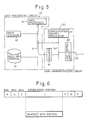
- Figure 5 shows the construction of a terminal apparatus as an embodiment of the present invention.
- reference numeral 40 denotes a data processing circuit
- 41 denotes a main processor
- 42 denotes a main storage
- 43 denotes an auxiliary storage
- 44 denotes a bus
- 50 denotes a data transmit/receive circuit
- 51 denotes communication control processor
- 52 denotes a line control circuit
- 53 denotes a register for resetting the main processor 41
- 54 denotes a bus
- 60 denotes a transmission line.
- the data processing circuit 40 includes the main processor 41, the main storage 42, auxiliary storage 43, and the bus 44.
- the main processor 41, and the data transmit/receive circuit 50 includes the communication control processor 51, the line control circuit 52, the register 53, and bus 54.
- the main processor 41 controls the original data processing functions of the terminal apparatus, including collecting, processing, and sending out data.
- the main storage 42 and the auxiliary storage 43 are connected to the main processor 41 through the bus 44.
- the auxiliary storage 43 stores programs and tables of parameters used in operations of the main processor 41.
- the programs in the auxiliary storage 43 is read out, and then are loaded in the main storage 42, and the main processor 41 carries out the above-mentioned control operations according to the loaded programs.
- the data transferred through the transmission line 60 from the master station is received at the line control circuit 52, and then is transferred through the bus 54 to the communication control processor 51.
- the communication control processor 51 monitors the received data, and determines whether or not the received data includes a reset command which commands resetting of the main processor 41, and a renewal command requesting renewal of the content of the auxiliary storage 43.
- the communication control processor 51 When the communication control processor 51 detects the reset command in the received data, the communication control processor 51 sets a predetermined data in the register 53. The output of the register 53 is applied to the main processor 41, and thereby the main processor 41 is reset.
- the communication control processor 51 When the communication control processor 51 detects the renewal command, the communication control processor 51 controls an operation of renewing the content in a predetermined area of the auxiliary storage 43, through the buses 44 and 54.
- the communication control processor 51 writes the transferred data in the predetermined area of the auxiliary storage 43 when the above renewal command is detected.
- the renewal means restructuring of data in a predetermined area of the auxiliary storage 43 using data which was held in advance in the terminal apparatus of Fig. 5, for example, in another area of the auxiliary storage 43 other than the area wherein the data renewal is requested.
- the communication control processor 51 directly controls the renewing operation of the auxiliary storage 43 in both the above ways, the renewal is carried out even when a malfunction has occurred in the main processor 41.
- the main storage 42 in the data processing circuit 40 corresponds to the aforementioned data processing means 6 in Figs. 3 and 4, and the auxiliary storage 43 corresponds to the data storage means in Fig. 4.
- the communication control processor 51 and the line control circuit 52 in the data transmit/receive circuit 50 realize the receiving means 2, the detecting means 3 and the data transferring means 4 in Fig. 3, and the communication control processor 51 and the register 53 realize the resetting means 5 in Fig. 3.
- the second detecting means 8 and the data renewing means 9 in Fig. 3, are also realized by the communication control processor 51.
- the data format shown in Fig. 6 is in accordance with the well-known format of the high level data link control (HDLC) procedure.
- HDLC high level data link control
- F denotes a flag sequence portion
- A denotes an address portion
- C denotes a control portion
- I denotes an information portion
- FCS denotes a frame check sequence portion
- control portion “C” indicates a type of the frame data.
- the control portion “C” indicates that the following information portion includes information other than the control commands and responses defined in the HDLC procedure, the content of the information portion "I" can be arbitrarily defined for a user within the HDLC procedure.
- the content of the information portion "I" is defined as a form of a packet consisting of two portions, a header portion and a data portion.
- a packet communication is carried out between the master station and the terminal station(s) in accordance with the HDLC procedure.
- the aforementioned reset command, and the renewal command can be defined in the header portion or data portion of Fig. 5, and the aforementioned replacement data for renewal operation can be transferred in the data portion of the information portion "I" of the frame shown in Fig. 6.
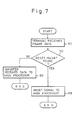
- Figure 7 shows an example of the operation of the communication control processor 51 according to the first aspect of the present invention when the terminal station receives frame data.
- the terminal apparatus receives frame data which has been transferred through the transmission line 60 from the master station, for example, having a format shown in Fig. 6.
- step 102 it is determined whether or not a reset packet is received, i. e., whether or not the received packet data as shown in Fig. 6, includes a reset command.
- the communication control processor 51 transfers the received data to the main processor 41 in the step 103.
- the communication control processor 51 sets the predetermined data in the register 53, and thus the output of the register 53 is applied to the main processor 41 to reset the main processor 41 in the step 105.
- Figure 8 shows an example of the operation of the main processor 41 when the main processor 41 receives a reset signal.
- the main processor 41 receives the output of the register 53, and is immediately reset in the step 201.
- This reset is a hardware reset, i. e., the resetting operation is carried out by applying a reset signal from the register 53 to a reset terminal of the main processor 41.
- the main processor 41 carries out an operation of initial program loading, i. e., in the step 202, a predetermined program stored in the auxiliary storage 43 is read out and is loaded in the main storage 42, and then the operation in accordance with the program is started by the main processor 41.
- a malfunction occurs in the data processing circuit 40 in a terminal apparatus as shown in Fig. 5, for example, when a part of data in the main storage 42 is damaged due to an accidental noise or the like, and then the occurrence of the malfunction is found at a master station by checking the data which has been transferred from the terminal apparatus to the master station, if the master station sends data including a reset command to the terminal apparatus, the reset command is detected at the terminal apparatus, and then, the terminal apparatus is reset and restarts itself.
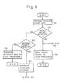
- Figure 9 shows an example of the operation of the communication control processor 51 according to the second aspect of the present invention when the terminal station receives a frame data.
- the operations in the steps 301, 302 and 305 in Fig. 9 are each equal to the operations in the steps 101, 102 and 105 in Fig. 7, respectively.
- step 303 it is determined whether or not a renewal packet is received, i. e., whether or not a renewal command requesting renewal of data stored in the auxiliary storage 43, is included in the received packet data.
- the communication control processor 51 transfers the received data to the main processor 41 in the step 304.
- the main processor 41 receives the transferred data, and then carries out a data processing operation using the transferred data in accordance with an existing program.
- the communication control processor 51 carries out a renewal operation of a predetermined area of the auxiliary storage 43, for example, in which area programs and a table of parameters to be used by the main processor 41 are stored, e. g., when the renewal packet includes a renewal command and replacement data for the renewal, the communication control processor 51 rewrites the above area using the replacement data, in the step 306.
- the communication control processor 5 may carry out the aforementioned reset control operation in the step 305, i. e., sets the predetermined data in the register 53, and thus the output of the register 53 is applied to the main processor 41 to reset the main processor 41.
- the main processor 41 carries out the aforementioned resetting operation of Fig. 8 after the content stored in a predetermined area of the auxiliary storage 43.
- the resetting operation following the renewal operation is optional.
- the resetting operation following the renewal operation may be eliminated.
- the remote control in the present invention eliminates a labor cost for a stand by operator, and reduces the recovery time when a malfunction occurs in an unmanned station.
Landscapes
- Engineering & Computer Science (AREA)
- Computer Networks & Wireless Communication (AREA)
- Signal Processing (AREA)
- Selective Calling Equipment (AREA)
- Computer And Data Communications (AREA)
- Communication Control (AREA)
Applications Claiming Priority (2)
| Application Number | Priority Date | Filing Date | Title |
|---|---|---|---|
| JP130822/88 | 1988-05-27 | ||
| JP63130822A JPH01298455A (ja) | 1988-05-27 | 1988-05-27 | 通信端末装置 |
Publications (2)
| Publication Number | Publication Date |
|---|---|
| EP0343630A2 true EP0343630A2 (de) | 1989-11-29 |
| EP0343630A3 EP0343630A3 (de) | 1991-03-13 |
Family
ID=15043525
Family Applications (1)
| Application Number | Title | Priority Date | Filing Date |
|---|---|---|---|
| EP19890109387 Withdrawn EP0343630A3 (de) | 1988-05-27 | 1989-05-24 | Durch Fernsteuerung rücksetzbare Endgerätvorrichtung |
Country Status (4)
| Country | Link |
|---|---|
| US (1) | US5136715A (de) |
| EP (1) | EP0343630A3 (de) |
| JP (1) | JPH01298455A (de) |
| CA (1) | CA1315369C (de) |
Cited By (2)
| Publication number | Priority date | Publication date | Assignee | Title |
|---|---|---|---|---|
| EP0573204A3 (en) * | 1992-06-05 | 1994-09-21 | Advanced Micro Devices Inc | Network connection system |
| EP1383097A1 (de) * | 2002-07-10 | 2004-01-21 | Telecom Italia S.p.A. | System zur Steuerung von entfernten Vorrichtungen |
Families Citing this family (40)
| Publication number | Priority date | Publication date | Assignee | Title |
|---|---|---|---|---|
| US5640504A (en) * | 1994-01-24 | 1997-06-17 | Advanced Computer Applications, Inc. | Distributed computing network |
| US6243838B1 (en) | 1997-05-13 | 2001-06-05 | Micron Electronics, Inc. | Method for automatically reporting a system failure in a server |
| US6170028B1 (en) * | 1997-05-13 | 2001-01-02 | Micron Electronics, Inc. | Method for hot swapping a programmable network adapter by using a programmable processor to selectively disabling and enabling power thereto upon receiving respective control signals |
| US6249828B1 (en) | 1997-05-13 | 2001-06-19 | Micron Electronics, Inc. | Method for the hot swap of a mass storage adapter on a system including a statically loaded adapter driver |
| US6253334B1 (en) | 1997-05-13 | 2001-06-26 | Micron Electronics, Inc. | Three bus server architecture with a legacy PCI bus and mirrored I/O PCI buses |
| US6195717B1 (en) | 1997-05-13 | 2001-02-27 | Micron Electronics, Inc. | Method of expanding bus loading capacity |
| US6163853A (en) | 1997-05-13 | 2000-12-19 | Micron Electronics, Inc. | Method for communicating a software-generated pulse waveform between two servers in a network |
| US6324608B1 (en) | 1997-05-13 | 2001-11-27 | Micron Electronics | Method for hot swapping of network components |
| US6418492B1 (en) | 1997-05-13 | 2002-07-09 | Micron Electronics | Method for computer implemented hot-swap and hot-add |
| US6292905B1 (en) | 1997-05-13 | 2001-09-18 | Micron Technology, Inc. | Method for providing a fault tolerant network using distributed server processes to remap clustered network resources to other servers during server failure |
| US6134615A (en) | 1997-05-13 | 2000-10-17 | Micron Electronics, Inc. | System for facilitating the replacement or insertion of devices in a computer system through the use of a graphical user interface |
| US6269412B1 (en) | 1997-05-13 | 2001-07-31 | Micron Technology, Inc. | Apparatus for recording information system events |
| US6338150B1 (en) * | 1997-05-13 | 2002-01-08 | Micron Technology, Inc. | Diagnostic and managing distributed processor system |
| US6247080B1 (en) | 1997-05-13 | 2001-06-12 | Micron Electronics, Inc. | Method for the hot add of devices |
| US6304929B1 (en) | 1997-05-13 | 2001-10-16 | Micron Electronics, Inc. | Method for hot swapping a programmable adapter by using a programmable processor to selectively disabling and enabling power thereto upon receiving respective control signals |
| US6202160B1 (en) | 1997-05-13 | 2001-03-13 | Micron Electronics, Inc. | System for independent powering of a computer system |
| US5892928A (en) * | 1997-05-13 | 1999-04-06 | Micron Electronics, Inc. | Method for the hot add of a network adapter on a system including a dynamically loaded adapter driver |
| US6202111B1 (en) | 1997-05-13 | 2001-03-13 | Micron Electronics, Inc. | Method for the hot add of a network adapter on a system including a statically loaded adapter driver |
| US6179486B1 (en) | 1997-05-13 | 2001-01-30 | Micron Electronics, Inc. | Method for hot add of a mass storage adapter on a system including a dynamically loaded adapter driver |
| US6173346B1 (en) | 1997-05-13 | 2001-01-09 | Micron Electronics, Inc. | Method for hot swapping a programmable storage adapter using a programmable processor for selectively enabling or disabling power to adapter slot in response to respective request signals |
| US6189109B1 (en) | 1997-05-13 | 2001-02-13 | Micron Electronics, Inc. | Method of remote access and control of environmental conditions |
| US6249834B1 (en) | 1997-05-13 | 2001-06-19 | Micron Technology, Inc. | System for expanding PCI bus loading capacity |
| US6330690B1 (en) * | 1997-05-13 | 2001-12-11 | Micron Electronics, Inc. | Method of resetting a server |
| US6145098A (en) | 1997-05-13 | 2000-11-07 | Micron Electronics, Inc. | System for displaying system status |
| US6243773B1 (en) | 1997-05-13 | 2001-06-05 | Micron Electronics, Inc. | Configuration management system for hot adding and hot replacing devices |
| US6499073B1 (en) | 1997-05-13 | 2002-12-24 | Micron Electronics, Inc. | System using programmable processor for selectively enabling or disabling power to adapter in response to respective request signals |
| US6269417B1 (en) | 1997-05-13 | 2001-07-31 | Micron Technology, Inc. | Method for determining and displaying the physical slot number of an expansion bus device |
| US6192434B1 (en) | 1997-05-13 | 2001-02-20 | Micron Electronics, Inc | System for hot swapping a programmable adapter by using a programmable processor to selectively disabling and enabling power thereto upon receiving respective control signals |
| US6282673B1 (en) | 1997-05-13 | 2001-08-28 | Micron Technology, Inc. | Method of recording information system events |
| US6219734B1 (en) | 1997-05-13 | 2001-04-17 | Micron Electronics, Inc. | Method for the hot add of a mass storage adapter on a system including a statically loaded adapter driver |
| US6249885B1 (en) | 1997-05-13 | 2001-06-19 | Karl S. Johnson | Method for managing environmental conditions of a distributed processor system |
| US6363497B1 (en) | 1997-05-13 | 2002-03-26 | Micron Technology, Inc. | System for clustering software applications |
| US6263387B1 (en) | 1997-10-01 | 2001-07-17 | Micron Electronics, Inc. | System for automatically configuring a server after hot add of a device |
| US6212585B1 (en) | 1997-10-01 | 2001-04-03 | Micron Electronics, Inc. | Method of automatically configuring a server after hot add of a device |
| US6199173B1 (en) | 1997-10-01 | 2001-03-06 | Micron Electronics, Inc. | Method for mapping environmental resources to memory for program access |
| US6175490B1 (en) | 1997-10-01 | 2001-01-16 | Micron Electronics, Inc. | Fault tolerant computer system |
| US6205503B1 (en) | 1998-07-17 | 2001-03-20 | Mallikarjunan Mahalingam | Method for the hot swap and add of input/output platforms and devices |
| US6223234B1 (en) | 1998-07-17 | 2001-04-24 | Micron Electronics, Inc. | Apparatus for the hot swap and add of input/output platforms and devices |
| IES20010610A2 (en) * | 2001-03-08 | 2002-09-18 | Richmount Computers Ltd | Reset facility for redundant processor using a fibre channel loop |
| EP2368949A4 (de) | 2008-12-24 | 2013-10-16 | Nat Maritime Res Inst | Fäulnishemmende beschichtungszusammensetzung, fäulnishemmender beschichtungsfilm und verfahren zur fäulnisverhinderung auf einer basis |
Family Cites Families (7)
| Publication number | Priority date | Publication date | Assignee | Title |
|---|---|---|---|---|
| US4335426A (en) * | 1980-03-10 | 1982-06-15 | International Business Machines Corporation | Remote processor initialization in a multi-station peer-to-peer intercommunication system |
| US4648031A (en) * | 1982-06-21 | 1987-03-03 | International Business Machines Corporation | Method and apparatus for restarting a computing system |
| US4514846A (en) * | 1982-09-21 | 1985-04-30 | Xerox Corporation | Control fault detection for machine recovery and diagnostics prior to malfunction |
| JPS607247A (ja) * | 1983-06-24 | 1985-01-16 | Nec Corp | リモ−トノ−ド制御方式 |
| US4635258A (en) * | 1984-10-22 | 1987-01-06 | Westinghouse Electric Corp. | System for detecting a program execution fault |
| US4803682A (en) * | 1985-03-04 | 1989-02-07 | Sanyo Electric Co., Ltd. | Resetting system |
| US4847749A (en) * | 1986-06-13 | 1989-07-11 | International Business Machines Corporation | Job interrupt at predetermined boundary for enhanced recovery |
-
1988
- 1988-05-27 JP JP63130822A patent/JPH01298455A/ja active Pending
-
1989
- 1989-05-23 CA CA000600421A patent/CA1315369C/en not_active Expired - Fee Related
- 1989-05-24 EP EP19890109387 patent/EP0343630A3/de not_active Withdrawn
- 1989-05-30 US US07/357,818 patent/US5136715A/en not_active Expired - Fee Related
Cited By (3)
| Publication number | Priority date | Publication date | Assignee | Title |
|---|---|---|---|---|
| EP0573204A3 (en) * | 1992-06-05 | 1994-09-21 | Advanced Micro Devices Inc | Network connection system |
| US5404544A (en) * | 1992-06-05 | 1995-04-04 | Advanced Micro Devices | System for periodically transmitting signal to/from sleeping node identifying its existence to a network and awakening the sleeping node responding to received instruction |
| EP1383097A1 (de) * | 2002-07-10 | 2004-01-21 | Telecom Italia S.p.A. | System zur Steuerung von entfernten Vorrichtungen |
Also Published As
| Publication number | Publication date |
|---|---|
| US5136715A (en) | 1992-08-04 |
| JPH01298455A (ja) | 1989-12-01 |
| EP0343630A3 (de) | 1991-03-13 |
| CA1315369C (en) | 1993-03-30 |
Similar Documents
| Publication | Publication Date | Title |
|---|---|---|
| US5136715A (en) | Terminal apparatus for resetting by remote control | |
| EP0491397B1 (de) | System zur Datenintegritätsgewährleistung | |
| WO1995020853A1 (en) | Networking module and method for fault-tolerant transmission of system management information | |
| JP3232393B2 (ja) | 分散処理システムのモジュール運転状態制御方法 | |
| JPS61152141A (ja) | 無線局監視方式 | |
| JPH0530119A (ja) | 通信装置 | |
| JP2818575B2 (ja) | 無線基地局の遠隔リセットシステム | |
| JP2666849B2 (ja) | 遠隔監視装置 | |
| JPH0463422B2 (de) | ||
| KR100250621B1 (ko) | 위성통신시스템에서의 중앙제어국 재기동시 데이터 복원장치 | |
| JP2530608B2 (ja) | ホ−ムテレホンシステム | |
| JP3163521B2 (ja) | 通信ケーブルの断線自動復旧システム | |
| JP2933471B2 (ja) | 監視装置 | |
| JPS58182359A (ja) | 電子交換機の自律系切替方式 | |
| JPS6248850A (ja) | 公衆回線結合リモ−ト障害デ−タ収集装置 | |
| JPH02155392A (ja) | 監視伝送装置 | |
| JPS62105243A (ja) | システム障害の復旧装置 | |
| CN114172556A (zh) | 卫星网络通信方法及系统 | |
| JPH0685942A (ja) | 障害自動通知方式 | |
| JPS61236241A (ja) | 情報伝送装置の縮退運用方式 | |
| JPS62225031A (ja) | 衛星通信用tdma端局装置 | |
| JPH03120917A (ja) | 無線基地局送受信機制御方式 | |
| JPH0271643A (ja) | ローカルエリアネットワーク | |
| JP2000099413A (ja) | リモート転送装置および方法 | |
| JPH05257915A (ja) | 障害復旧方式 |
Legal Events
| Date | Code | Title | Description |
|---|---|---|---|
| PUAI | Public reference made under article 153(3) epc to a published international application that has entered the european phase |
Free format text: ORIGINAL CODE: 0009012 |
|
| AK | Designated contracting states |
Kind code of ref document: A2 Designated state(s): DE FR GB |
|
| PUAL | Search report despatched |
Free format text: ORIGINAL CODE: 0009013 |
|
| AK | Designated contracting states |
Kind code of ref document: A3 Designated state(s): DE FR GB |
|
| 17P | Request for examination filed |
Effective date: 19910701 |
|
| 17Q | First examination report despatched |
Effective date: 19930720 |
|
| STAA | Information on the status of an ep patent application or granted ep patent |
Free format text: STATUS: THE APPLICATION HAS BEEN WITHDRAWN |
|
| 18W | Application withdrawn |
Withdrawal date: 19950725 |