EP0343521A2 - Atemschutzmaske - Google Patents
Atemschutzmaske Download PDFInfo
- Publication number
- EP0343521A2 EP0343521A2 EP89108999A EP89108999A EP0343521A2 EP 0343521 A2 EP0343521 A2 EP 0343521A2 EP 89108999 A EP89108999 A EP 89108999A EP 89108999 A EP89108999 A EP 89108999A EP 0343521 A2 EP0343521 A2 EP 0343521A2
- Authority
- EP
- European Patent Office
- Prior art keywords
- gas
- filter
- respirator
- gas sensor
- mask according
- Prior art date
- Legal status (The legal status is an assumption and is not a legal conclusion. Google has not performed a legal analysis and makes no representation as to the accuracy of the status listed.)
- Granted
Links
Images


Classifications
-
- A—HUMAN NECESSITIES
- A62—LIFE-SAVING; FIRE-FIGHTING
- A62B—DEVICES, APPARATUS OR METHODS FOR LIFE-SAVING
- A62B18/00—Breathing masks or helmets, e.g. affording protection against chemical agents or for use at high altitudes or incorporating a pump or compressor for reducing the inhalation effort
- A62B18/08—Component parts for gas-masks or gas-helmets, e.g. windows, straps, speech transmitters, signal-devices
- A62B18/088—Devices for indicating filter saturation
Definitions
- the invention relates to a respirator with a filter in the air intake, in particular a respirator with an electrically operated ventilation device which sucks in ambient air and presses it into the respirator, the filter being arranged in front of the ventilation device.
- the invention has for its object to carry out a filter change only after reaching a certain filter load, without compromising the safety of the user. According to the invention this is achieved with the aid of a gas sensor which is arranged behind the filter, the gas sensor changing its electrical resistance or its voltage or its capacitance in contact with the gas.
- the gas sensor is set in such a way that any gas content in the respiratory air flow behind the filter that is harmful to the user of the respiratory mask is immediately displayed.
- the gas sensor preferably already comes into operation when the harmful gas content approaches the admissibility limit.
- the ventilation device is connected via a flexible hose line to the breathing mask that envelops the user's head.
- the hose line connection is designated by 2.
- the respirator mask has an intake port 3.
- the two ports 2 and 3 are closed with screw closures.
- the closures are unscrewed.
- the closure of the connecting piece 3 is unscrewed.
- a filter is installed there.
- the filter, not shown, is e.g. B. an activated carbon filter.
- the ventilation device 1 sucks in ambient air through the filter.
- the ambient air is cleaned in the filter.
- the suction takes place by means of a lamellar wheel 4, which is rotatably mounted in the housing of the ventilation device 1 and is driven by a motor 5.
- the motor 5 is an electric motor which is supplied with a low-voltage current by a battery which is arranged in part 6 of the ventilation device 1.
- a gas sensor 7 is located in the ventilation device 1.
- the gas sensor 7 is connected via a feed line 8 to the cavity in which the lamellar wheel 4 runs.
- Electronics 9 are linked to the gas sensor.
- Figure 2 shows the interaction of electronics and sensor in a schematic representation.
- the sensor sends a signal to a signal amplifier 9.
- the amplified signal arrives in an analog / digital converter, the output of which is shown on a display if required appears.
- the display is labeled 11.
- a limit value monitor 12 is provided in parallel.
- the limit value monitor 12 is also connected to the signal amplifier 9 and makes contact for an optical or acoustic alarm 13 as soon as a permissible value is exceeded.
- the limit value monitor 12 can also be used to monitor the battery voltage, which is essential for sensor operation.
- the gas sensor 7 is designed for the expected gas or the expected gases. Systems that are particularly sensitive to the specified gases are advantageous.
- Figure 3 shows a sensor for explosive gases.
- Flammable gases are very common. These include e.g. B. acetone, acetylene, ethane, ethyl alcohol, ethylene, ammonia, benzene, n-butane, chlorobenzene hydrogen cyanide, dimethyl ether, 1,4-dioxane, acetic acid, glycerol, carbon monoxide, methane, methyl chloride, naphthalene, nitrobenzene, phenol, propane, propylene , Carbon disulfide, hydrogen sulfide, toluene, vinyl chloride, hydrogen.
- the concentration must have reached a certain minimum value before a gas / air mixture ignites.
- the sensor of Figure 3 measures the concentration of the gas-air mixture. He works on the principle of "catalytic combustion” or "warming". The gas-air mixture reaches an active catalyst, a heated measuring element, by diffusion or with the aid of a sample gas pump. The higher the concentration of the combustible constituents, the more it heats up Sensor that, together with a passive element, forms the branch of a Wheatstone bridge. The bridge detuning is proportional to the gas concentration.
- a measuring amplifier takes over the signals, processes them and forwards them as shown in FIG. 2 to the display instrument or to the alarm part.
- the measuring chamber is denoted by 15, the active catalyst by 16, the passive by 17.
- the gas penetrates a sintered metal surface of the measuring chamber, passes through a flame protection wall or flame check valve 18 and arrives at the active catalyst, which reacts in the manner described above.
- the gas sensor shown in FIG. 3 requires sufficient oxygen for the catalytic combustion. With increasing gas concentration, however, the oxygen content decreases. The heating of the sensor decreases, the proportionality to the gas concentration is in question. As a result, the gas sensor according to FIG. 3 is preferably used to determine the lower explosion limit, that is the minimum oxygen content for an explosion. In addition, there is an upper explosion limit that indicates the maximum oxygen content at which there is still a risk of explosion. If the gas concentration is to be measured beyond the lower explosion limit, a gas sensor according to FIG. 4 is suitable. The gas sensor according to FIG. 4 works on the principle of "heat conduction" and is based on the fact that the thermal conductivity of the gases changes with the concentration. The sensor according to FIG.
- FIG. 4 is also based on a bridge circuit in which a heated platinum wire 20 serves as a measuring and comparison sensor.
- the measuring chamber is designated 21, the comparison chamber with 22.
- the platinum wire 20 is designed as a helix and is guided through the measuring chamber and the comparison chamber.
- the gas passes through a correspondingly permeable, z. B. made of sintered metal, through a flame arrester and reaches the platinum wire 20, where it causes different heating of the current-loaded platinum wire 20.
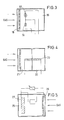
- a sensor for the oxygen content is shown in Figure 5.
- a cathode 26 made of a large-area, electron-conducting material.
- a reaction with the oxygen of the measuring gas takes place on its active surface.
- the oxygen breaks down into hydroxyl ions.
- electrical energy is created.
- the current that flows between cathode 26 and anode 27 is proportional to oxygen. The response of such a cell is extremely quick.
- Toxic gases can be particularly dangerous. Frequently occurring gases are e.g. B. acetaldehyde, formic acid, ammonia, arsenic, chlorine, chlorine dioxide, hydrogen cyanide, methylene chloride, fluorine, hydrogen fluoride, formaldehyde, carbon dioxide, carbon monoxide, osmium tetroxide, propane, sulfur dioxide, sulfur hexafluoride, hydrogen sulfide, tetrachloroethane, toluene, chloroform, hydrogen peroxide.
- gases are e.g. B. acetaldehyde, formic acid, ammonia, arsenic, chlorine, chlorine dioxide, hydrogen cyanide, methylene chloride, fluorine, hydrogen fluoride, formaldehyde, carbon dioxide, carbon monoxide, osmium tetroxide, propane, sulfur dioxide, sulfur hexafluoride, hydrogen sulfide, tetrachloroethane, to
- Toxic gases can be measured with semiconductor sensors.
- the chemoadsorption on metal oxide semiconductors plays a role on their surface and causes changes in the conductivity, depending on the gas concentration.
- Figure 6 shows such a gas sensor.
- the metal oxide semiconductor is designated 30 and held between two electrodes 31 and 32.
- the reaction is intensified with the aid of a heating device which is formed from a ceramic body and a heating coil 34 enclosed in the ceramic body 33.
- Figure 7 shows a gas sensor for the display of carbon monoxide.
- the structure of the gas sensor according to FIG. 7 essentially corresponds to that of the gas sensor according to FIG. 5. However, instead of one anode, there are two electrodes, a reference electrode 35 and a counter electrode 36.
Landscapes
- Health & Medical Sciences (AREA)
- Pulmonology (AREA)
- General Health & Medical Sciences (AREA)
- Business, Economics & Management (AREA)
- Emergency Management (AREA)
- Respiratory Apparatuses And Protective Means (AREA)
- Investigating Or Analyzing Materials By The Use Of Electric Means (AREA)
- Investigating Or Analyzing Materials By The Use Of Fluid Adsorption Or Reactions (AREA)
- Acyclic And Carbocyclic Compounds In Medicinal Compositions (AREA)
- Materials For Medical Uses (AREA)
Abstract
Description
- Die Erfindung betrifft eine Atemschutzmaske mit Filter in der Luftansaugung, insbesondere Atemschutzmaske mit elektrisch betriebenem Belüftungsgerät, das Umgebungsluft ansaugt und in die Atemschutzmaske drückt, wobei der Filter vor dem Belüftungsgerät angeordnet ist.
- Atemschutzmasken finden z. B. bei der Brandbekämpfung oder beim Einsatz in toxisch oder mit radioaktiven Aerosolen verseuchten Räumen Verwendung. Der Einsatz von Atemschutzmasken ist in Krisenfällen ganz besonders groß. Dann dient die Atemschutzmaske der Reinigung der Atemluft von biologischen oder chemischen Kampfmitteln. Die Reinigung erfolgt über Filter, wobei in erster Linie Aktivkohlefilter Verwendung finden.
- Alle bekannten Filter haben eine begrenzte Betriebszeit. Deshalb müssen die Filter nach Erreichen einer bestimmten Betriebsdauer ausgewechselt werden. Diese Betriebsdauer ist so gewählt, daß der Filter zum Zeitpunkt der Auswechslung noch ausreichende Filterfunktionen besitzt.
- Problematisch ist die Einhaltung der vorgesehenen Auswechslungszeit. Außerdem ist es unwirtschaftlich, wenn der Filter unabhängig von seiner Beladung nach Erreichen einer bestimmten Betriebsdauer ausgewechselt wird. Der Erfindung liegt die Aufgabe zugrunde, einen Filterwechsel erst nach Erreichen einer bestimmten Filterbeladung durchzuführen, ohne dabei die Sicherheit des Benutzers zu beeinträchtigen. Nach der Erfindung wird das mit Hilfe eines Gassensors erreicht, der hinter dem Filter angeordnet ist, wobei der Gassensor in Berührung mit dem Gas seinen elektrischen Widerstand oder seine Spannung oder seine Kapazität ändert. Der Gassensor wird so eingestellt, daß jeder für den Benutzer der Atemschutzmaske schädliche Gasgehalt in der Atemluftströmung hinter dem Filter sofort angezeigt wird. Vorzugsweise tritt der Gassensor bereits in Funktion, wenn der Schadgasgehalt sich der Zulässigkeitsgrenze nähert.
- Die Unteransprüche geben bevorzugte Ausführungen der Erfindungen wieder.
- In der Zeichnung sind verschiedene Ausführungsbeispiele dargestellt.
- Mit 1 ist ein Belüftungsgerät für eine nicht dargestellte Atemschutzmaske bezeichnet. Das Belüftungsgerät ist im Betriebsfall über eine flexible Schlauchleitung mit der den Kopf des Benutzers umhüllenden Atemschutzmaske verbunden. Der Schlauchleitungsanschluß ist mit 2 bezeichnet.
- Die Atemschutzmaske besitzt einen Ansaugstutzten 3. In der Zeichnung nach Figur 1 sind die beiden Stutzen 2 und 3 mit Schraubverschlüssen verschlossen. Zur Verbindung mit der flexiblen Schlauchleitung werden die Verschlüsse abgeschraubt. Ferner wird der Verschluß des Anschlußstutzens 3 abgeschraubt. Dort wird ein Filter montiert. Das nicht dargestellte Filter ist z. B. ein Aktivkohlefilter.
- Das Belüftungsgerät 1 saugt durch den Filter Umgebungsluft an. Die Umgebungsluft wird im Filter gereinigt.
- Die Ansaugung erfolgt mittels eines Lamellenrades 4, welches im Gehäuse des Belüftungsgerätes 1 drehbeweglich gelagert ist und mit einem Motor 5 angetrieben wird. Der Motor 5 ist ein Elektromotor, der durch eine Batterie mit Strom niedriger Spannung versorgt wird, welche im Teil 6 des Belüftungsgerätes 1 angeordnet ist.
- Im Belüftungsgerät 1 befindet sich ein Gassensor 7. Der Gassensor 7 ist über eine Zuleitung 8 mit dem Hohlraum verbunden, in dem das Lamellenrad 4 läuft.
- Mit dem Gassensor ist eine Elektronik 9 verknüpft.
- Figur 2 zeigt das Zusammenwirken von Elektronik und Sensor in einer schematischen Darstellung. Nach Figur 2 gibt der Senor ein Signal an eine Signalverstärkung 9. Das verstärkte Signal gelangt in einen Analog/Digitalwandler, dessen Ausgang bei Bedarf auf einem Display erscheint. Das Display ist mit 11 bezeichnet. Parallel dazu ist eine Grenzwertüberwachung 12 vorgesehen. Die Grenzwertüberwachung 12 ist gleichfalls an den Signalverstärker 9 angeschlossen und gibt Kontakt für einen optischen oder akustischen Alarm 13, sobald ein zulässiger Wert überschritten wird. Die Grenzwertüberwachung 12 kann auch zur Überwachung der Batteriespannung verwendet werden, die maßgeblich für den Sensorbetrieb ist.
- Der Gassensor 7 ist auf das erwartete Gas bzw. auf die erwarteten Gase ausgelegt. Vorteilhaft sind Systeme, die besonders empfindlich auf die vorgegebenen Gase reagieren. Figur 3 zeigt einen Sensor für explosive Gase.
- Voraussetzung für eine Gasexplosion sind: brennbare Gase oder Dämpfe, Sauerstoff in ausreichender Menge, eine Zündquelle, eine bestimmte Gaskonzentration. Brennbare Gase kommen sehr häufig vor. Dazu gehören z. B. Aceton, Acethylen, Ethan, Ethylalkohol, Ethylen, Ammoniak, Benzol, n-Butan, Chlorbenzol Cyanwasserstoff, Dimethylether, Dioxan-1,4, Essigsäure, Glycerin, Kohlenmonoxid, Methan, Methylchlorid, Naphthalin, Nitrobenzol, Phenol, Propran, Propylen, Schwefelkohlenstoff, Schwefelwasserstoff, Toluol, Vinylchlorid, Wasserstoff.
- Chemische Explosionen sind meistens sehr rasch ablaufende Oxydationen. Der dafür notwendige Sauerstoff ist in der Umgebungsluft in ausreichender Menge vorhanden. Desgleichen gibt es Zündquellen sehr häufig. Dazu gehören brennende Zigaretten, Funken, beim Schalten elektrischer Kontakte, aufeinanderschlagende Werkstoffe, Lichtbögen beim Schweißen usw.
- Nicht jede beliebige Gasmenge führt zur Explosion. Die Konzentration muß einen bestimmten Minimalwert erreicht haben, ehe sich ein Gasluftgemisch entzündet. Der Sensor nach Figur 3 mißt die Konzentration des Gas-Luftgemisches. Er arbeitet nach dem Prinzip der "Katalytischen Verbrennung" oder "Wärmetönung". Das Gas-Luftgemisch gelangt durch Diffusion oder mit Hilfe einer Meßgaspumpe an einen aktiven Katalysator, ein beheiztes Meßelement. Je höher die Konzentration der brennbaren Bestandteile ist, umso mehr erwärmt sich der Sensor, der zusammen mit einem passiven Element den Zweig einer Wheatstoneschen Brücke bildet. Die Brückenverstimmung ist der Gaskonzentration proportional. Ein Meßverstärker übernimmt die Signale, verarbeitet sie, leitet sie wie in Figur 2 dargestellt zum Anzeigeinstrument bzw. zum Alarmteil weiter.
- In Figur 3 ist die Meßkammer mit 15 bezeichnet, der aktive Katalysator mit 16, der passive mit 17. Das Gas durchdringt eine Sintermetallfläche der Meßkammer, passiert eine Flammschutzwand bzw. Flammrückschlagsperre 18 und gelangt an den aktiven Katalysator, welcher in oben beschriebener Weise reagiert.
- Der in Figur 3 dargestellte Gassensor setzt für die katalytische Verbrennung ausreichenden Sauerstoff voraus. Mit zunehmender Gaskonzentration aber sinkt der Sauerstoffanteil. Die Erwärmung des Sensors nimmt ab, die Proportionalität zur Gaskonzentration steht damit in Frage. Infolge dessen findet der Gassensor nach Figur 3 vorzugsweise Einsatz zur Bestimmung der unteren Explosionsgrenze, das ist der minimale Sauerstoffgehalt für eine Explosion. Darüber hinaus gibt es eine obere Explosionsgrenze, die den maximalen Sauerstoffgehalt kennzeichnet, bei dem noch Explosionsgefahr gegeben ist. Sofern die Gaskonzentration über die untere Explosionsgrenze hinaus gemessen werden soll, ist ein Gassensor nach Figur 4 geeignet. Der Gassensor nach Figur 4 arbeitet nach dem Prinzip der "Wärmeleitung" und basiert darauf, daß die Wärmeleitfähigkeit der Gase sich mit der Konzentration ändert. Auch der Sensor nach Figur 4 basiert auf einer Brückenschaltung, bei der ein beheizter Platindraht 20 als Meß- und Vergleichssensor dient. In Figur 4 ist die Meßkammer mit 21, die Vergleichskammer mit 22 bzeichnet. Der Platindraht 20 ist als Wendel ausgebildet und durch die Meßkammer und die Vergleichskammer hindurchgeführt. Das Gas tritt wie bei dem Gassensor nach Figur 3 durch eine entsprechend durchlässig ausgebildete, z. B. aus Sintermetall hergestellte Gehäusewand, durch eine Flammrückschlagsperre und gelangt an den Platindraht 20, wo es unterschiedliche Erwärmungen des mit Strom beaufschlagten Platindrahtes 20 verursacht.
- Gase, die weder brennbar sind noch auf den Menschen toxisch wirken, sind dann gefährlich, wenn sie keinen Sauerstoff beinhalten. Ein Meßwertgeber für den Sauerstoffgehalt ist in Figur 5 dargestellt. Zwischen der atmosphärischen Luft und einem basischen Elektrolyten 25 befindet sich eine Kathode 26 aus einem großflächigen, elektronenleitenden Material. An ihrer aktiven Oberfläche spielt sich eine Reaktion mit dem Sauerstoff des Meßgases ab. Dabei baut sich der Sauerstoff zu Hydroxyl-Ionen ab. Gleichzeitig entsteht elektrische Energie. Der Strom, der zwischen Kathode 26 und Anode 27 fließt, ist der Sauerstoff proportional. Die Reaktion ist einer solchen Zelle ist äußerst schnell.
- Von besonderer Gefährlichkeit können toxische Gase sein. Häufig vorkommende Gase sind z. B. Acetaldehyd, Ameisensäure, Ammoniak, Arsenwasserstoff, Chlor, Chlordioxid, Cyanwasserstoff, Methylenchlorid, Fluor, Fluorwasserstoff, Formaldehyd, Kohlendioxid, Kohlenmonoxid, Osmiumtetroxid, Propan, Schwefeldioxid, Schwefelhexafluorid, Schwefelwasserstoff, Tetrachlrethan, Toluol, Chloroform, Wasserstoffperoxid.
- Toxische Gase lassen sich mit Halbleitersensoren messen. Dabei spielt die Chemoadsorption an Metalloxid-Halbleitern eine Rolle an deren Oberfläche und verursacht Änderungen der Leitfähigkeit, und zwar in Abhängigkeit von der Gaskonzentration.
- Figur 6 zeigt einen solchen Gassensor. Der Metalloxid-Halbleiter ist mit 30 bezeichnet und zwischen zwei Elektroden 31 und 32 gehalten. Die Reaktion wird mit Hilfe einer Beheizungseinrichtung verstärkt, welche aus einem Keramikkörper und einer in den Keramikkörper 33 eingeschlossene Heizwendel 34 gebildet wird.
- Figur 7 zeigt einen Gassensor für die Anzeige von Kohlenmonoxid. Im wesentlichen entspricht der Aufbau des Gassensors nach Figur 7 dem des Gassensors nach Figur 5. Es findet sich jedoch anstelle der einen Anode zwei Elektroden, eine Referenzelektrode 35 und eine Gegenelektrode 36.
Claims (5)
Priority Applications (1)
| Application Number | Priority Date | Filing Date | Title |
|---|---|---|---|
| AT89108999T ATE99970T1 (de) | 1988-05-27 | 1989-05-19 | Atemschutzmaske. |
Applications Claiming Priority (2)
| Application Number | Priority Date | Filing Date | Title |
|---|---|---|---|
| DE3818052 | 1988-05-27 | ||
| DE3818052A DE3818052A1 (de) | 1988-05-27 | 1988-05-27 | Atemschutzmaske |
Publications (3)
| Publication Number | Publication Date |
|---|---|
| EP0343521A2 true EP0343521A2 (de) | 1989-11-29 |
| EP0343521A3 EP0343521A3 (en) | 1990-12-05 |
| EP0343521B1 EP0343521B1 (de) | 1994-01-12 |
Family
ID=6355260
Family Applications (1)
| Application Number | Title | Priority Date | Filing Date |
|---|---|---|---|
| EP89108999A Expired - Lifetime EP0343521B1 (de) | 1988-05-27 | 1989-05-19 | Atemschutzmaske |
Country Status (4)
| Country | Link |
|---|---|
| US (1) | US5018518A (de) |
| EP (1) | EP0343521B1 (de) |
| AT (1) | ATE99970T1 (de) |
| DE (2) | DE3818052A1 (de) |
Cited By (7)
| Publication number | Priority date | Publication date | Assignee | Title |
|---|---|---|---|---|
| AU645959B3 (en) * | 1993-11-05 | 1994-01-27 | Purecab (Australia) Pty Ltd | Respiratory filter indicator |
| WO1996012523A1 (en) * | 1994-10-24 | 1996-05-02 | Minnesota Mining And Manufacturing Company | Exposure indicator with alarm signal |
| WO1996012524A1 (en) * | 1994-10-24 | 1996-05-02 | Minnesota Mining And Manufacturing Company | Exposure indicating apparatus |
| WO1998024516A1 (en) * | 1996-12-07 | 1998-06-11 | T.E.M. Technische Entwicklung Und Management Gmbh | Improvements to gas-masks |
| WO2000054841A1 (de) | 1999-03-17 | 2000-09-21 | T.E.M.! Technische Entwicklungen Und Management Gmbh | Sensorvorrichtung und verfahren zur detektion von in luft enthaltenen gasen oder dämpfen |
| DE19911869A1 (de) * | 1999-03-17 | 2000-09-28 | T E M Tech Entwicklungen Und M | Neuartige Atemschutzmaske mit Sensor-Mikrosystem |
| DE19911867A1 (de) * | 1999-03-17 | 2000-10-19 | T E M Tech Entwicklungen Und M | Sensorsystem zur Detektion von Gasen und Dämpfen in Luft |
Families Citing this family (18)
| Publication number | Priority date | Publication date | Assignee | Title |
|---|---|---|---|---|
| DE4132680C2 (de) * | 1991-10-01 | 1994-02-10 | Draegerwerk Ag | Atemschutzmaske mit Innenhalbmaske und Schadstoffindikator |
| DE4133235A1 (de) * | 1991-10-07 | 1993-04-08 | Draegerwerk Ag | Geblaeseunterstuetztes atemschutzgeraet mit einem aufsetzbaren steuerteil |
| DE4202025C2 (de) * | 1992-01-25 | 1995-02-02 | Draegerwerk Ag | Gebläseunterstütztes Atemschutzgerät mit einstellbarer Gebläseleistung |
| US5165395A (en) * | 1992-02-14 | 1992-11-24 | Ricci Mark R | Ultra-violet germicidal mask system |
| DE4214239C2 (de) * | 1992-04-30 | 1994-06-16 | Draegerwerk Ag | Atemschutzmaske mit einem indikator |
| SE503155C2 (sv) * | 1994-07-28 | 1996-04-01 | Comasec International Sa | Sätt och anordning för funktionskontroll vid andningsapparat |
| AUPN191095A0 (en) * | 1995-03-23 | 1995-04-27 | Safety Equipment Australia Pty Ltd | Positive air-purifying respirator management system |
| US6186140B1 (en) * | 1997-03-14 | 2001-02-13 | 3M Innovative Properties Company | Respiratory filter element having a storage device for keeping track of filter usage and a system for use therewith |
| US6199550B1 (en) * | 1998-08-14 | 2001-03-13 | Bioasyst, L.L.C. | Integrated physiologic sensor system |
| GB9929745D0 (en) * | 1999-12-17 | 2000-02-09 | Secr Defence | Determining the efficiency of respirators and protective clothing and other improvements |
| US6701925B1 (en) | 2002-04-11 | 2004-03-09 | Todd A. Resnick | Protective hood respirator |
| US20040182394A1 (en) * | 2003-03-21 | 2004-09-23 | Alvey Jeffrey Arthur | Powered air purifying respirator system and self contained breathing apparatus |
| US20060048777A1 (en) * | 2003-03-21 | 2006-03-09 | Interspiro, Inc. | Apparatus and method for providing breathable air and bodily protection in a contaminated environment |
| US7647927B2 (en) * | 2003-08-22 | 2010-01-19 | Wilcox Industries Corp. | Self-contained breathing system |
| US8077884B2 (en) * | 2004-02-19 | 2011-12-13 | So Sound Solutions, Llc | Actuation of floor systems using mechanical and electro-active polymer transducers |
| US7981064B2 (en) | 2005-02-18 | 2011-07-19 | So Sound Solutions, Llc | System and method for integrating transducers into body support structures |
| CN107441831A (zh) | 2010-08-06 | 2017-12-08 | 斯科特科技股份有限公司 | 提供空气净化过滤器的使用寿命结束指示的传感器装置 |
| DE102015208443A1 (de) | 2015-05-06 | 2016-11-10 | Robert Bosch Gmbh | Filter für ein Atemluftanalysegerät, Atemluftanalysegerät und Verfahren zum Überwachen eines Filters |
Family Cites Families (13)
| Publication number | Priority date | Publication date | Assignee | Title |
|---|---|---|---|---|
| GB480507A (en) * | 1936-07-11 | 1938-02-23 | Pirelli | Improvements relating to filters and purifiers employed for conditioning air, for example for respiration, or other gas by freeing it from poisonous gases and other injurious or undesired constitutents |
| FR843542A (fr) * | 1937-09-29 | 1939-07-05 | Pirelli | Dispositif pour la signalisation de l'épuisement des filtres antigaz |
| US3586486A (en) * | 1968-02-23 | 1971-06-22 | Bosch Arma Corp | Gas analyzer |
| US3911413A (en) * | 1974-02-08 | 1975-10-07 | Richard A Wallace | Thermally activated warning system |
| US3902485A (en) * | 1974-02-08 | 1975-09-02 | Richard A Wallace | Chemically activated warning system |
| US4146887A (en) * | 1977-08-05 | 1979-03-27 | American Optical Corporation | Respirator cartridge end-of-service life indicator |
| US4331141A (en) * | 1979-04-10 | 1982-05-25 | Naum Pokhis | Arrangement for protection of organs of respiration |
| DE3019387C2 (de) * | 1980-05-21 | 1986-01-23 | Siemens AG, 1000 Berlin und 8000 München | Dünnschicht-Halbleiter-Gassensor mit einem in den Sensoraufbau integrierten Heizelement |
| JPS58191962A (ja) * | 1982-05-07 | 1983-11-09 | Hitachi Ltd | ガス検出素子 |
| JPS59120944A (ja) * | 1982-12-28 | 1984-07-12 | Shinkosumosu Denki Kk | 飽和炭化水素ガス検知素子 |
| US4579643A (en) * | 1983-11-18 | 1986-04-01 | Ngk Insulators, Ltd. | Electrochemical device |
| DE3613512C3 (de) * | 1986-04-22 | 1994-09-29 | Auergesellschaft Gmbh | Elektrische Warneinrichtung zur Anzeige des Erschöpfungszustandes eines Schadgase zurückhaltenden Gasfilters |
| JPS63218852A (ja) * | 1987-03-09 | 1988-09-12 | Yokogawa Electric Corp | 排ガス中のo↓2及び可燃ガス濃度測定装置 |
-
1988
- 1988-05-27 DE DE3818052A patent/DE3818052A1/de not_active Withdrawn
-
1989
- 1989-05-19 AT AT89108999T patent/ATE99970T1/de not_active IP Right Cessation
- 1989-05-19 EP EP89108999A patent/EP0343521B1/de not_active Expired - Lifetime
- 1989-05-19 DE DE89108999T patent/DE58906666D1/de not_active Expired - Fee Related
- 1989-05-26 US US07/358,304 patent/US5018518A/en not_active Expired - Fee Related
Cited By (10)
| Publication number | Priority date | Publication date | Assignee | Title |
|---|---|---|---|---|
| AU645959B3 (en) * | 1993-11-05 | 1994-01-27 | Purecab (Australia) Pty Ltd | Respiratory filter indicator |
| WO1996012523A1 (en) * | 1994-10-24 | 1996-05-02 | Minnesota Mining And Manufacturing Company | Exposure indicator with alarm signal |
| WO1996012524A1 (en) * | 1994-10-24 | 1996-05-02 | Minnesota Mining And Manufacturing Company | Exposure indicating apparatus |
| WO1998024516A1 (en) * | 1996-12-07 | 1998-06-11 | T.E.M. Technische Entwicklung Und Management Gmbh | Improvements to gas-masks |
| WO2000054841A1 (de) | 1999-03-17 | 2000-09-21 | T.E.M.! Technische Entwicklungen Und Management Gmbh | Sensorvorrichtung und verfahren zur detektion von in luft enthaltenen gasen oder dämpfen |
| WO2000054840A1 (de) | 1999-03-17 | 2000-09-21 | T.E.M.! Technische Entwicklungen Und Management Gmbh | Verfahren und sensorvorrichtung zur detektion von in luft enthaltenen gasen oder dämpfen |
| DE19911869A1 (de) * | 1999-03-17 | 2000-09-28 | T E M Tech Entwicklungen Und M | Neuartige Atemschutzmaske mit Sensor-Mikrosystem |
| DE19911867A1 (de) * | 1999-03-17 | 2000-10-19 | T E M Tech Entwicklungen Und M | Sensorsystem zur Detektion von Gasen und Dämpfen in Luft |
| DE19911867C2 (de) * | 1999-03-17 | 2002-02-21 | T E M Techn Entwicklungen Und | Sensorsystem zur Detektion von Gasen und Dämpfen in Luft |
| DE19911869B4 (de) * | 1999-03-17 | 2004-03-25 | T.E.M.! Techn. Entwicklungen Und Management Gmbh | Neuartige Atemschutzmaske mit Sensor-Mikrosystem und Verfahren zum Betreiben derselben |
Also Published As
| Publication number | Publication date |
|---|---|
| ATE99970T1 (de) | 1994-01-15 |
| EP0343521A3 (en) | 1990-12-05 |
| US5018518A (en) | 1991-05-28 |
| DE58906666D1 (de) | 1994-02-24 |
| DE3818052A1 (de) | 1989-12-07 |
| EP0343521B1 (de) | 1994-01-12 |
Similar Documents
| Publication | Publication Date | Title |
|---|---|---|
| EP0343521B1 (de) | Atemschutzmaske | |
| EP0246444B1 (de) | Warneinrichtung zur Anzeige des Erschöpfungszustandes eines Gasfilters | |
| DE4002843C1 (en) | Protective breathing mask with filter - having gas sensors in-front and behind with difference in their signals providing signal for change of filter | |
| EP2373991B1 (de) | Messgerät und verfahren zum erfassen des gehaltes von öl, kohlenwasserstoffen und oxidierbaren gasen in luft oder druckluft | |
| DE69401993T2 (de) | Explosionsgeschützte, mikrowellengeheitzte Extraktionsvorrichtung | |
| DE3786127T2 (de) | Sauerstoffkonzentrationsmessvorrichtung. | |
| EP1459062B1 (de) | Verfahren und vorrichtung zur messung des sauerstoffgehaltes in einem abgeschlossenen zielraum | |
| DE1960517B2 (de) | Vorrichtung zum Aufrechterhalten atembarer Luft | |
| DE102009000660A1 (de) | Batteriemodul | |
| DE3729337C2 (de) | ||
| EP1165186B1 (de) | Verfahren und sensorvorrichtung zur detektion von in luft enthaltenen gasen oder dämpfen | |
| WO2018192711A1 (de) | Kompaktes messgerät und verfahren zum erfassen von kohlenwasserstoffen | |
| EP0459944A1 (de) | Vorrichtung und Verfahren für einen objektgebundenen Brandschutz von elektrischen und/oder elektronischen Anlagen sowie Verwendung der Vorrichtung | |
| DE2813050A1 (de) | Flammenionisationsdetektor | |
| DE907223C (de) | Elektrischer Anzeiger fuer Halogendaempfe und Daempfe von Halogenverbindungen | |
| DE4009107C2 (de) | ||
| EP0255146B1 (de) | Verfahren und Vorrichtung zum Testen von Filtern in explosionsgefährdeter Umgebung | |
| DE4003244C2 (de) | ||
| DE19911869A1 (de) | Neuartige Atemschutzmaske mit Sensor-Mikrosystem | |
| AT229440B (de) | Einrichtung zur Verhütung von Explosionen von Gasen, die durch einen Raum, insbesondere einen elektrischen Abscheider, strömen | |
| DE4431875C2 (de) | Sensorelement | |
| DE4412447A1 (de) | Explosionswarner bei explosionsgefährdeten Gasen, insbesondere Methan | |
| DE4342804C1 (de) | Sicherung gegen Ozonemissionen für ozonerzeugende und/oder ozonvernichtende Vorrichtungen | |
| DE3840021C2 (de) | ||
| DE3505670C2 (de) | Vorrichtung zur Erkennung von Verunreinigungen der Außenluft und zur Unterbrechung der Außenluftzufuhr zu Fahrzeugkabinen bzw. Raumzellen |
Legal Events
| Date | Code | Title | Description |
|---|---|---|---|
| PUAI | Public reference made under article 153(3) epc to a published international application that has entered the european phase |
Free format text: ORIGINAL CODE: 0009012 |
|
| AK | Designated contracting states |
Kind code of ref document: A2 Designated state(s): AT BE CH DE ES FR GB GR IT LI LU NL SE |
|
| PUAL | Search report despatched |
Free format text: ORIGINAL CODE: 0009013 |
|
| AK | Designated contracting states |
Kind code of ref document: A3 Designated state(s): AT BE CH DE ES FR GB GR IT LI LU NL SE |
|
| 17P | Request for examination filed |
Effective date: 19910211 |
|
| 17Q | First examination report despatched |
Effective date: 19920709 |
|
| GRAA | (expected) grant |
Free format text: ORIGINAL CODE: 0009210 |
|
| AK | Designated contracting states |
Kind code of ref document: B1 Designated state(s): AT BE CH DE ES FR GB GR IT LI LU NL SE |
|
| PG25 | Lapsed in a contracting state [announced via postgrant information from national office to epo] |
Ref country code: GR Free format text: LAPSE BECAUSE OF FAILURE TO SUBMIT A TRANSLATION OF THE DESCRIPTION OR TO PAY THE FEE WITHIN THE PRESCRIBED TIME-LIMIT Effective date: 19940112 Ref country code: ES Free format text: THE PATENT HAS BEEN ANNULLED BY A DECISION OF A NATIONAL AUTHORITY Effective date: 19940112 Ref country code: BE Effective date: 19940112 |
|
| REF | Corresponds to: |
Ref document number: 99970 Country of ref document: AT Date of ref document: 19940115 Kind code of ref document: T |
|
| ITF | It: translation for a ep patent filed | ||
| REF | Corresponds to: |
Ref document number: 58906666 Country of ref document: DE Date of ref document: 19940224 |
|
| GBT | Gb: translation of ep patent filed (gb section 77(6)(a)/1977) |
Effective date: 19940204 |
|
| ET | Fr: translation filed | ||
| PG25 | Lapsed in a contracting state [announced via postgrant information from national office to epo] |
Ref country code: LU Free format text: LAPSE BECAUSE OF NON-PAYMENT OF DUE FEES Effective date: 19940531 Ref country code: LI Effective date: 19940531 Ref country code: CH Effective date: 19940531 |
|
| PLBE | No opposition filed within time limit |
Free format text: ORIGINAL CODE: 0009261 |
|
| STAA | Information on the status of an ep patent application or granted ep patent |
Free format text: STATUS: NO OPPOSITION FILED WITHIN TIME LIMIT |
|
| 26N | No opposition filed | ||
| EAL | Se: european patent in force in sweden |
Ref document number: 89108999.7 |
|
| REG | Reference to a national code |
Ref country code: CH Ref legal event code: PL |
|
| PGFP | Annual fee paid to national office [announced via postgrant information from national office to epo] |
Ref country code: GB Payment date: 19970410 Year of fee payment: 9 |
|
| PGFP | Annual fee paid to national office [announced via postgrant information from national office to epo] |
Ref country code: FR Payment date: 19970411 Year of fee payment: 9 |
|
| PGFP | Annual fee paid to national office [announced via postgrant information from national office to epo] |
Ref country code: AT Payment date: 19970422 Year of fee payment: 9 |
|
| PGFP | Annual fee paid to national office [announced via postgrant information from national office to epo] |
Ref country code: SE Payment date: 19970423 Year of fee payment: 9 |
|
| PGFP | Annual fee paid to national office [announced via postgrant information from national office to epo] |
Ref country code: NL Payment date: 19970428 Year of fee payment: 9 |
|
| PGFP | Annual fee paid to national office [announced via postgrant information from national office to epo] |
Ref country code: DE Payment date: 19970510 Year of fee payment: 9 |
|
| PG25 | Lapsed in a contracting state [announced via postgrant information from national office to epo] |
Ref country code: GB Free format text: LAPSE BECAUSE OF NON-PAYMENT OF DUE FEES Effective date: 19980519 Ref country code: AT Free format text: LAPSE BECAUSE OF NON-PAYMENT OF DUE FEES Effective date: 19980519 |
|
| PG25 | Lapsed in a contracting state [announced via postgrant information from national office to epo] |
Ref country code: SE Free format text: LAPSE BECAUSE OF NON-PAYMENT OF DUE FEES Effective date: 19980520 |
|
| PG25 | Lapsed in a contracting state [announced via postgrant information from national office to epo] |
Ref country code: FR Free format text: LAPSE BECAUSE OF NON-PAYMENT OF DUE FEES Effective date: 19980531 |
|
| PG25 | Lapsed in a contracting state [announced via postgrant information from national office to epo] |
Ref country code: NL Free format text: LAPSE BECAUSE OF NON-PAYMENT OF DUE FEES Effective date: 19981201 |
|
| GBPC | Gb: european patent ceased through non-payment of renewal fee |
Effective date: 19980519 |
|
| EUG | Se: european patent has lapsed |
Ref document number: 89108999.7 |
|
| NLV4 | Nl: lapsed or anulled due to non-payment of the annual fee |
Effective date: 19981201 |
|
| PG25 | Lapsed in a contracting state [announced via postgrant information from national office to epo] |
Ref country code: DE Free format text: LAPSE BECAUSE OF NON-PAYMENT OF DUE FEES Effective date: 19990302 |
|
| REG | Reference to a national code |
Ref country code: FR Ref legal event code: ST |
|
| PG25 | Lapsed in a contracting state [announced via postgrant information from national office to epo] |
Ref country code: IT Free format text: LAPSE BECAUSE OF NON-PAYMENT OF DUE FEES Effective date: 20050519 |