EP0343372A2 - Appareil pour la contre-gravité et procédé - Google Patents
Appareil pour la contre-gravité et procédé Download PDFInfo
- Publication number
- EP0343372A2 EP0343372A2 EP89107001A EP89107001A EP0343372A2 EP 0343372 A2 EP0343372 A2 EP 0343372A2 EP 89107001 A EP89107001 A EP 89107001A EP 89107001 A EP89107001 A EP 89107001A EP 0343372 A2 EP0343372 A2 EP 0343372A2
- Authority
- EP
- European Patent Office
- Prior art keywords
- mold member
- mold
- molten metal
- upper mold
- gas impermeable
- Prior art date
- Legal status (The legal status is an assumption and is not a legal conclusion. Google has not performed a legal analysis and makes no representation as to the accuracy of the status listed.)
- Withdrawn
Links
Images

Classifications
-
- B—PERFORMING OPERATIONS; TRANSPORTING
- B22—CASTING; POWDER METALLURGY
- B22D—CASTING OF METALS; CASTING OF OTHER SUBSTANCES BY THE SAME PROCESSES OR DEVICES
- B22D18/00—Pressure casting; Vacuum casting
- B22D18/06—Vacuum casting, i.e. making use of vacuum to fill the mould
Definitions
- This invention relates to the vacuum countergravity casting of metal in a gas permeable, mold and, more particularly, to a method and apparatus for vacuum countergravity casting with reduced bending stresses in the mold to permit use of thinner molds or molds having a greater ratio of horizontal mold dimension to vertical mold dimension with reduced risk of damage to the mold.
- the vacuum countergravity casting apparatus includes a mold having a porous, gas permeable upper mold member and a lower mold member secured together, a vacuum chamber around the upper mold member, and means for submerging the bottom of the lower mold member in a pool of molten metal while evacuating the chamber to draw molten metal up into mold cavities in the upper mold member through ingates in the bottom of the lower mold member.
- the upper and lower mold members may comprise gas permeable, low temperature, resin-bonded sand mold members which are adhesively secured (glued) together along a common horizontal parting plane.
- the horizontal mold dimension has been increased relative to the vertical mold dimension.
- the ratio of horizontal mold dimension to vertical dimension has been increased to 7 or 8:1 from a previously used ratio of about 4:1.
- the mold becomes susceptible to damage as a result of the aforementioned pressure differential across the vertical mold dimension. If the mold is not sufficiently strong, it can deflect or even fail from bending stresses developed in the mold and result in production of defective castings or damaging melt run-out into the casting chamber.
- the invention comprehends a vacuum countergravity casting apparatus comprising a mold having a porous, gas permeable upper mold member at least in part defining a mold cavity therein and a lower mold member engaged to the upper mold member and having a bottom ingate passage for supplying molten metal to the mold cavity from an underlying molten metal pool, and a housing defining a chamber for confronting the gas permeable, upper mold member and having a septum in the chamber for contacting the upper mold member to transmit ambient pressure thereto in opposition to ambient pressure transmitted to the lower mold member when subambient pressure is established between the septum and the upper mold member to draw molten metal into the mold cavity. Bending stresses in the mold are substantially reduced by transmitting opposing ambient pressure to the upper mold member and lower mold member.
- the septum may comprise a gas permeable or gas impermeable member.
- the invention further contemplates a vacuum countergravity casting apparatus comprising a gas permeable upper mold member having an upper surface and at least in part defining a mold cavity therein, a lower mold member engaged to the upper mold member and having a bottom ingate passage to supply molten metal to the mold cavity when the bottom of the lower mold member is positioned in molten metal, a gas impermeable member having a portion overlying the upper surface of the upper mold member in contact therewith at a plurality of spaced apart contact regions distributed across the upper surface and having a peripheral portion, sealing means disposed between the peripheral portion of the gas impermeable member and the mold, means for providing ambient pressure above the gas impermeable member, and means for providing relatively reduced (i.e., subambient) pressure between the gas impermeable member and upper surface.
- a gas permeable upper mold member having an upper surface and at least in part defining a mold cavity therein
- a lower mold member engaged to the upper mold member and having a bottom ingate passage to supply
- the gas impermeable member confines the reduced pressure therebeneath to the first mold member and mold cavity to effect filling of the mold cavity with molten metal and transmits through the plurality of spaced apart contact regions ambient pressure, such as atmospheric pressure, to the upper mold member in opposition to ambient pressure transmitted to the lower mold member to substantially reduce the bending stresses developed in the mold when subambient pressure is established in the mold cavity.
- the contact regions distribute ambient pressure across the horizontal dimension of the upper surface while allowing reduced pressure to extend sufficiently thereacross to evacuate the mold cavities.
- the peripheral portion of the gas impermeable member is in sealed relation to the wall of a housing defining a chamber confronting the upper mold member.
- the peripheral portion is in sealed relation to the mold itself, either the upper or lower mold member.
- the upper and lower mold members may be held together solely by ambient pressure (i.e., without adhesive) when reduced pressure is applied beneath the gas impermeable member to the upper mold member and mold cavity.
- a plurality of spaced apart standoffs are disposed between the gas impermeable member and upper surface of the upper mold member to provide the plurality of spaced apart contact regions therebetween.
- a vacuum conduit preferably is connected to the gas impermeable member to provide reduced pressure therebeneath in the space around the standoffs.
- the gas impermeable member may be flexible or include flexible portions to allow the standoffs to intimately contact the gas impermeable member and upper mold member.
- the invention further contemplates a vacuum countergravity casting apparatus comprising a housing that defines a vacuum chamber confronting the gas permeable upper mold member and that includes a relatively movable upper portion and lower portion with a rigid, gas permeable septum secured to the upper portion of the housing and overlying the upper mold member for contacting the upper mold member to transmit ambient pressure on the housing to the upper mold member, means for sealing the mold to the lower portion of the housing, and means for providing subambient pressure in the vacuum chamber to evacuate a mold cavity at least partially defined in the upper mold member through the gas permeable septum when the lower mold member is immersed in a molten metal pool.
- the mold and the housing are relatively moved toward one another, as permitted by relative movement between the upper and lower portions of the housing, so as to contact the septum and upper mold member for transmitting ambient pressure on the housing to the upper mold member in opposition to ambient pressure transmitted to the lower mold member, whereby bending stresses in the mold are minimized and the upper mold member and lower mold member are held together by the ambient pressure without adhesive.
- the invention also contemplates a method for vacuum countergravity casting conducted in such a way to minimize bending stresses in the mold and preferably to hold the upper mold member and lower mold member together without adhesive.
- the invention further contemplates a method and apparatus for vacuum countergravity wherein the gas impermeable member is releasably engaged to and carries the peripheral wall of the vacuum chamber relative to a mold and wherein the gas impermeable member and the peripheral wall of the vacuum chamber are disengageable and relatively movable when the peripheral wall contacts the mold to facilitate sealing of the peripheral wall to the mold.
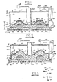
- Fig. 1 illustrates a vacuum countergravity casting apparatus in accordance with one embodiment of the invention.
- the apparatus includes a container 10 of molten metal 12 to be drawn up into the mold 14.
- the mold 14 includes a porous, gas permeable upper mold member 16 and a lower mold member 18, which may be gas permeable or impermeable.
- the upper and lower mold members 16,18 may be adhesively or otherwise secured together along juxtaposed surfaces that define a parting line or plane 20 to provide a unitary mold.
- each ingate passage 24 extends from the bottom of the lower mold member to a respective mold cavity 22 that is formed at least in part into the upper mold member.
- the number, size and spacing of mold cavities 22 and ingate passages 24 will vary with the type of part to be cast and the particular metal to be cast as explained in U.S. Patent 4,340,108, the teachings of which are incorporated herein by reference.
- Upper and lower mold members 16,18 can be made of resin-bonded sand in accordance with known mold practice wherein a mixture of sand or equivalent particles and bonding material is formed to shape and cured or hardened against a contoured metal pattern (not shown) having the desired complementary contour or profile for the parting surfaces and the mold cavities in the upper and lower mold members.
- the bonding material may comprise inorganic or organic thermal or chemical setting plastic resin or equivalent bonding material.
- the bonding material is usually present in minor percentage, such as less than about 5% by weight of the mixture.
- the resin-bonded sand mold members 16,18 may be adhesively secured together along parting plane 20 to form mold 14.
- the invention is advantageously used with low-temperature, resin-bonded sand molds.
- the invention is not limited to resin-bonded sand molds and may find use with other types of non-metallic refractory molds; e.g., investment molds of the high temperature ceramic type known in the art, such as investment molds made from alumina, zircon, fused quartz and like ceramic particulate and binder, such as colloidal silica.
- a ceramic mold shall include a mold of the bonded sand type, high temperature ceramic type or other mold types made of non-metallic refractory materials.
- Upper mold member 16 and lower mold member 18 may be made of the same or different ceramic composition.
- upper mold member is made of a porous, gas permeable material which permits gases to be withdrawn from mold cavities 22 when a relative vacuum is applied to upper surface 26 of the upper mold member.
- Mold 14 may be made in various exterior shapes (e.g., circular, rectangular, etc.).
- a particularly convenient and efficient mold is one in which upper and lower mold members 16,18 are generally cylindrical discs in shape.
- Such a mold is shown in Fig. 1 as having a horizontal mold dimension (mold diameter) H and a vertical mold dimension (mold thickness) V.
- upper surface 26 of the upper mold member typically is irregular in contour since it is formed of generally uniform thickness mold material applied onto the irregular contour of a pattern to reduce the weight of mold material required.
- the pattern is removed after mold formation in accordance with known practice.
- Bottom 18a of the lower mold member may also have an irregular contour for this same reason, although a flat horizontal bottom is preferred.
- gas impermeable sheet metal member 30 is shown overlying and following the contour of upper surface 26 of the upper mold member.
- Member 30 is a septum which divides the chamber C formed by the housing 46 into upper and lower parts and includes a central portion 32 having a plurality of standoffs or projections 34 spaced apart on the inner or lower side thereof facing upper surface 26 and extending toward and into engagement with the upper surface to provide a plurality of spaced apart contact regions 25 between the central portion 32 and upper surface 26.
- the standoffs 34 are disposed in a dispersed pattern across portion 32 to effect contact with upper surface 26 at a plurality of spaced apart contact regions distributed across its horizontal dimension or area.
- the standoffs distribute ambient pressure applied on the gas impermeable member across the upper surface 26 and form a space 36 between the gas impermeable member and upper surface 26.
- Space 36 extends to peripheral portion 40 of the gas impermeable member to allow reduced pressure to sufficiently confront upper surface 26 for evacuation of mold cavities 22.
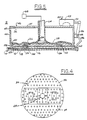
- standoffs Although a particular dispersed pattern of standoffs is shown in Fig. 4, other patterns can be used to achieve the same end. Moreover, the standoffs may have configurations other than the generally conical cross-sectional shape shown.
- Peripheral portion 40 is placed in sealed relation to the upper surface 26 around its periphery.
- the peripheral portion includes a peripheral annular (cylindrical) rim 42.
- Rim 42 preferably is secured to the bottom end of depending annular (cylindrical) wall 44 of metal housing or box 46.
- Sealing means in the form of an annular sealing member 48 is disposed between peripheral rim 42 and upper surface 26 and may be joined to one of them.
- the peripheral portion of the gas impermeable member may be sealed to the wall 44 higher up in the housing 46 (e.g., see Fig. 6.).
- the gas impermeable member is thus peripherally sealed substantially about the upper mold member in Figs. 1 and 6 such that space 36 confronts the upper mold member.
- Housing or box 46 and lower mold member 18 may be engaged together by multiple conventional clamps 50 (only one shown) spaced around the circumference or periphery of the mold.
- Each clamp 50 includes a fluid cylinder 52 mounted on housing 46, a plunger 54 actuated by the cylinder and a clamp arm 56 pivotable about pin 58. Extension of the plunger 54 causes clamp end 60 on the clamp arm to grip lower mold member 18 to engage the housing 46 and the lower mold member together to effect sealing action between upper surface 26, sealing member 48 and rim 42.
- Housing 46 is supported from a known mechanism for advancing the housing and mold clamped thereto toward the molten metal to submerge bottom 18a therein and away from the molten metal after casting.
- Rim 42 of the gas impermeable member is connected to central portion 32 by annular flexible portion 38 that allows the standoffs 34 of the central portion to intimately contact upper surface 26 when the space 36 and mold cavities 22 are evacuated.
- Central portion 32 of the gas impermeable member includes an opening 62 that sealingly receives an open end of vacuum pipe or conduit 64.
- the vacuum pipe is joined to central portion 32 by multiple stiffening ribs 66 welded or otherwise attached to the vacuum pipe and to the central portion.
- the opposite end of the vacuum pipe extends through the top wall 47 of housing 46 and is connected to a source of vacuum or reduced pressure; e.g., a conventional vacuum pump 68.
- the vacuum pipe can be attached to and supported by the top wall 47 of the housing.
- Housing 46 is provided with one or more apertures 49 (one shown) connecting the interior chamber C of the housing above the gas impermeable member with ambient space S surrounding the housing. Molten metal in container 10 also is exposed to space S. Space S may be defined by another external housing (not shown) enclosing the vacuum countergravity casting apparatus illustrated or may simply constitute unenclosed ambient space surrounding the casting apparatus.
- Space S and chamber C may include a natural atmosphere providing atmospheric pressure on the gas impermeable member and molten metal or an artificial atmosphere, such as a protective inert gas atmosphere, providing an artificial ambient pressure on the gas impermeable member and molten metal.
- an artificial atmosphere such as a protective inert gas atmosphere, providing an artificial ambient pressure on the gas impermeable member and molten metal.
- chamber C and space S will have a common atmosphere exerting an equal ambient pressure on the gas impermeable member and the molten metal in container 10.
- chamber C and space S may have atmospheres differing from one another in composition or other properties.
- a relative vacuum may also be employed in both chamber C and space S prior to filling the mold cavities to effect degassing of the casting apparatus and molten metal. Chamber C and space S can then be backfilled with a protective artificial atmosphere following degassing to carry out the countergravity casting process.
- the vacuum pump is actuated to provide reduced pressure in space 36 between the gas impermeable member and upper surface 26 and thus in mold cavities 22 to draw molten metal into mold cavities 22 through ingate passages 24.
- external ambient (atmospheric or artificial ) pressure in chamber C bears against the outer or upper side of the gas impermeable member.
- the vertical mold dimension V for a given mold size can be reduced to provide a lower cost mold or the horizontal mold dimension H can be increased relative to the vertical mold dimension V to cast more parts per mold.
- the invention permits use of molds whose H/V ratio is about 7:1 and greater so that more castings can be produced from a single larger size mold without increased use of mold material per casting.
- clamps 50 are released from lower mold member 18 to allow separation of the mold from the housing.
- Fig. 2 illustrates another embodiment of the invention similar to that shown in Fig. 1 with the exception that a modified gas impermeable member or septum 70 is used to effect sealed relation with the lower mold member, not the upper mold member.
- a modified gas impermeable member or septum 70 is used to effect sealed relation with the lower mold member, not the upper mold member.
- like reference numerals are used for like features or components of Fig. 1 and different reference numerals are used only when the Figures differ from one another.
- modified gas impermeable member 70 includes central portion 72 having a plurality of spaced apart standoffs 74 for providing a plurality of spaced apart contact regions 75 across the horizontal dimension of upper surface 26 of the upper mold member 16.
- the gas impermeable member further includes depending annular (cylindrical) peripheral sleeve portion 76 connected to central portion 72 by annular flexible portion 77.
- Sleeve portion 76 includes peripheral annular rim 78 that preferably is attached to the bottom end of depending annular wall 44 of housing 46. Rim 78 is placed in sealed relation against annular sealing member 48. Sealing member 48 in turn is in sealed relation to peripheral shoulder 29 of lower mold member 18 whose diameter is selected to expose shoulder 29 on the lower mold member.
- Housing 16 and the lower mold member are clamped together by clamps 50 (only one shown) to effect sealing action between shoulder 29, sealing member 48 and rim 78.
- the gas impermeable member is thereby disposed in sealed relation substantially about the upper mold member.
- Sleeve portion 76 is relatively rigid to withstand the force applied to effect sealing action.
- Fig. 3 illustrates a gas impermeable member 80 different from that of the Fig. 2 in that depending annular peripheral sleeve portion 86 includes flexible portion 88 at an intermediate location thereon.
- sleeve portion 86 includes a rigid upper cylindrical portion 86a connected to lower rigid cylindrical portion 86b by flexible portion 88.
- Lower portion 86b includes annular peripheral rim 87.
- a relatively rigid L-shaped corner 89 is thus provided between central portion 82 and depending annular sleeve portion 86.
- Flexible portion 88 functions in a similar manner as flexible portion 77 of the embodiment of Fig. 2 to allow a plurality of spaced apart standoffs (not shown) on central portion 82 to intimately contact the upper surface of the upper mold member.
- FIG. 5 A further embodiment of the vacuum countergravity casting apparatus of the invention is illustrated in Fig. 5.
- a flexible gas impermeable membrane member 100 is positioned in housing 46 in overlying relation on upper surface 126 of upper mold member 116.
- the peripheral portion 101 of the gas impermeable member includes annular peripheral sealing rim 102 which may be integral with or sealingly attached to the peripheral portion.
- Rim 102 in turn is attached to the inner periphery of annular (cylindrical) depending wall 44 of housing 46 as shown with a bottom portion of the rim 102 extending below the bottom end of wall 44 to sealingly engage annular peripheral shoulder 129 of lower mold member 118 when housing 46 and lower mold member 118 are clamped together by clamps 50 (only one shown). Sealing rim 102 thus constitutes sealing means disposed between the peripheral portion of the gas impermeable member and peripheral shoulder 129 of the lower mold member.
- the gas impermeable membrane 100 includes a central opening 104 receiving vacuum pipe 64 and is sealingly attached to the vacuum pipe around the central opening so that reduced pressure can be established between the gas impermeable membrane and upper surface 126.
- the flexible gas impermeable membrane may be made of silicone rubber or other flexible non-metallic material and may be pre-shaped to conform approximately to upper surface 126 or it may be in initial flat sheet form and have sufficient flexibility to conform to upper surface 126 by application of ambient pressure thereon when the mold cavities 122 are evacuated. Even though the gas impermeable membrane is pressed in contact against upper surface 126 by ambient pressure, the relatively high surface roughness of the upper surface 126 in effect provides a plurality of standoffs dispersed across the lateral or horizontal area thereof to establish a plurality of spaced apart contact regions between the upper surface and the gas impermeable membrane. As a result, there are spaces between the gas impermeable membrane and upper surface 126 through which the vacuum can extend toward the peripheral sealing rim 102 across upper surface 126 to evacuate mold cavities 122.
- FIG. 6 Still another embodiment of the invention is illustrated in Fig. 6 where like reference numerals are used for like features or components of previous Figures while different reference numerals are used for different components.
- the gas impermeable member 200 which may be a sheet metal or flexible member as described hereinabove, is sealingly attached to the inner periphery of gas impermeable housing wall 44 above the upper mold member 16.
- the gas impermeable member includes an annular peripheral lip portion 202 that is attached to the wall 44 by a plurality of rivets 204 (two shown) or other suitable fastening means with an annular sealing gasket 206 disposed between peripheral lip portion 202 and the wall such that a reduced pressure can be maintained in the space 36 between the gas impermeable member and upper mold member and around a plurality of standoffs 210 therebetween.
- Another annular sealing gasket 208 is positioned between the annular bottom end of wall 44 and the peripheral shoulder 29 of the lower mold member 18 to this same end.
- sealing gasket 206, sealing gasket 208 and the portion of wall 44 between the gaskets constitute sealing means disposed between the peripheral portion 202 of the gas impermeable member and the lower mold member to peripherally seal peripheral portion 202 to the mold.
- FIG. 7 A further embodiment of the invention is illustrated in Fig. 7 where like reference numerals are used for like features or components of previous Figures while different reference numerals are used for different components.
- Fig. 7 differs from that of Fig. 6 primarily in that the housing 16 includes the gas impermeable member 200 sealingly secured to the inner periphery of the gas impermeable wall 44 by an annular, flexible, sealing connector member 212 to allow relative movement between the gas impermeable member 200 and the peripheral wall 44.
- the peripheral wall 44 is open at the upper end thereof and not closed by a top wall.
- the peripheral wall 44 includes an inwardly projecting annular stop member 214 secured on the thinner periphery thereof above the gas permeable member 200.
- a vacuum conduit 64 is sealingly attached to the gas impermeable member 200 to evacuate the space 36 between the gas impermeable member 200 and the upper mold member 16.
- the vacuum conduit 64 (or the gas impermeable member 200 itself) is connected to a mechanism (not shown) for raising and lowering the housing 46 relative to a molten metal pool.
- the stop member 214 is positioned to be engaged and carried by the peripheral portion 202 of the gas impermeable member 200 during relative movement between the gas impermeable member and the mold 14. For example, the gas impermeable member 200 is moved initially toward the mold 14 with the stop member 214 of the peripheral wall 44 engaged on the gas impermeable member 200 (shown in phantom engaged to the peripheral wall 44).
- the gas impermeable member 200 with the peripheral wall 44 engaged thereon is moved toward the mold 14 until the seal 208 of the peripheral wall 44 sealingly engages the lower mold member 18. Thereafter, the gas impermeable member 200 continues to move downwardly, disengaging from the peripheral wall 44, until it contacts the upper mold member 16, as shown in Fig. 7. This relative movement between the peripheral wall 44 and the gas impermeable member 200 facilitates and enhances sealing engagement between the seal 208 of the peripheral wall 44 and the upper mold member 16. With the peripheral wall 44 sealed to the lower mold member 18 and the gas impermeable member 200 contacting the upper mold member 16, the lower mold portion 18 is immersed in the molten metal pool and the space 36 is evacuated by conduit 64 to urge molten metal into the mold cavities 22.
- the upper and lower mold members 16,18 are held together by ambient pressure and bending stresses in the mold 14 are minimized.
- Either the gas impermeable member 200 or the mold 14 or both can be moved in this embodiment of the invention to engage and disengage the housing 46 and the mold 14.
- the mold 14 is withdrawn from the molten metal pool as described hereinabove for the other embodiments.
- the gas impermeable member 200 and the peripheral wall 40 are then removed from the mold 14 by establishing ambient pressure in the space 36 and raising the gas impermeable member 200 away from the upper mold member 16. Initially, the gas impermeable member moves independently of the peripheral wall 44 of disengage itself from the upper mold member 16. Eventually as it is raised, the gas impermeable member 200 engages and carries the peripheral wall 44 with it (see phantom lines in Fig. 7) to disengage the peripheral wall 44 from sealing engagement with the lower mold member 18.
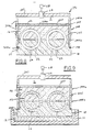
- Figs. 8-9 illustrate still another embodiment of the invention different from the above-described embodiments in that the housing 346 includes a gas permeable septum 330 (e.g., a rigid, porous plate) fastened to the gas impermeable peripheral wall 344 of the housing in overlying relationship to the upper surface 26 of the upper mold member 16.
- the top wall 347 and the peripheral wall 344 of the housing form a vacuum chamber C in which the gas permeable septum 330 is disposed to divide the chamber C into upper and lower parts.
- the septum 330 is fastened between segments of an upper portion 344a of the peripheral wall 344.
- An annular, seal 349 is secured to the upper portion 344a of the peripheral wall to seal the outside periphery of the gas permeable septum 330.
- the upper portion 344a is connected to a lower portion 344b of the peripheral wall 344 by an annular flexible, joint 345 sealingly attached to the outer peripheries of the upper and lower portions 344a,344b. In this way, the upper and lower portions 344a,344b of the peripheral wall are movable relative to one another.
- the lower portion 344b of the peripheral wall includes a bottom lip 344c having an annular, sealing gasket 348 thereon for sealing engagement with an upwardly facing shoulder 29 on the lower mold member 18.
- the ambient pressure on the housing 346 is transmitted to the rigid, gas permeable septum 330 through the upper portion 344a of the peripheral wall 344.
- the septum 330 in turn transmits this ambient pressure to the upper mold member 16 through the plurality of contact regions provided therebetween as a result of roughness of the upper surface 26 of the upper mold member 16.
- the ambient pressure transmitted to the upper mold member 16 is in opposition to ambient pressure transmitted to the lower mold member 18 to minimize bending stresses in the mold 14 as in the above-described embodiments.
- the vacuum drawn in the vacuum chamber C will also cause the upper and lower mold members 16,18 to be pressed and held together by the opposing ambient pressure exerted thereon, eliminating the need to glue the upper and lower mold members 16,18 together.
- This same vacuum is used to evacuate the annular mold cavities 22 through the gas permeable upper mold member 16 and the gas permeable septum 330 to draw molten metal 12 from the pool through ingate passages 24 into the mold cavities 22 to effect casting.
- sealing means is disposed between said peripheral portion and the upper mold member.
- said sealing means is disposed between said peripheral portion and the lower mold member.
- the gas impermeable member is a sheet metal member having a plurality of spaced apart standoffs extending toward the upper mold member for providing said contact regions and forming a space between the sheet metal member and upper mold member around the standoffs.
- the gas impermeable member is a flexible membrane.
- said wall is in sealed relation to the lower mold member.
- said ambient pressure is atmospheric pressure and said means for providing same above said septum is a vent in said housing.
- said means for providing subambient pressure is a vacuum conduit sealingly attached to said septum.
- the septum comprises sheet metal having a plurality of spaced apart standoffs engaging the upper mold member for providing said contact regions and forming a space between the sheet metal and upper mold member around the standoffs.
- said wall includes a stop member adapted to be engaged by movement of said septum such that said septum caries said wall toward and away from said mold.
- stop member disengages from said septum when said wall sealingly engages said mold.
- an apparatus for vacuum countergravity casting of molten metal which comprises:
- the plurality of contact regions comprise a plurality of spaced apart standoffs between said overlying portion of the gas impermeable septum and said upper surface.
- the mold has a ratio of horizontal mold dimension to vertical mold dimension of 7:1 and greater.
- a peripheral portion of the gas impermeable member releasably engages with an inwardly extending stop member on the peripheral wall.
Landscapes
- Engineering & Computer Science (AREA)
- Mechanical Engineering (AREA)
- Molds, Cores, And Manufacturing Methods Thereof (AREA)
Applications Claiming Priority (2)
| Application Number | Priority Date | Filing Date | Title |
|---|---|---|---|
| US07/198,229 US4858672A (en) | 1988-05-25 | 1988-05-25 | Countergravity casting apparatus and method |
| US198229 | 1994-02-16 |
Publications (2)
| Publication Number | Publication Date |
|---|---|
| EP0343372A2 true EP0343372A2 (fr) | 1989-11-29 |
| EP0343372A3 EP0343372A3 (fr) | 1990-12-27 |
Family
ID=22732524
Family Applications (1)
| Application Number | Title | Priority Date | Filing Date |
|---|---|---|---|
| EP19890107001 Withdrawn EP0343372A3 (fr) | 1988-05-25 | 1989-04-19 | Appareil pour la contre-gravité et procédé |
Country Status (4)
| Country | Link |
|---|---|
| US (1) | US4858672A (fr) |
| EP (1) | EP0343372A3 (fr) |
| JP (1) | JPH0220653A (fr) |
| BR (1) | BR8902283A (fr) |
Families Citing this family (8)
| Publication number | Priority date | Publication date | Assignee | Title |
|---|---|---|---|---|
| US5029630A (en) * | 1990-07-03 | 1991-07-09 | General Motors Corporation | Differential pressure, countergravity casting apparatus using a vertically parted mold stack clamp mechanism |
| US5044420A (en) * | 1990-08-13 | 1991-09-03 | General Motors Corporation | Vacuum-assisted, countergravity casting apparatus and method |
| US5062466A (en) * | 1991-05-10 | 1991-11-05 | General Motors Corporation | Countergravity casting apparatus and method |
| DE112006000461T5 (de) * | 2005-02-22 | 2008-03-13 | Milwaukee School Of Engineering, Milwaukee | Gießverfahren |
| WO2007079482A2 (fr) * | 2006-01-03 | 2007-07-12 | Adolf Hetke | Systeme de coulee de metal, moule usine, procede et objets fabriques selon le procede |
| WO2009034344A2 (fr) * | 2007-09-14 | 2009-03-19 | Natural Resources (2000) Limited | Moulage d'article |
| WO2012092244A2 (fr) | 2010-12-29 | 2012-07-05 | Android Industries Llc | Réservoir doseur assisté par dépression |
| GB201108003D0 (en) * | 2011-05-13 | 2011-06-29 | Materialise Dental Nv | Endodontic treatment simulation system |
Citations (4)
| Publication number | Priority date | Publication date | Assignee | Title |
|---|---|---|---|---|
| US4340108A (en) * | 1979-09-12 | 1982-07-20 | Hitchiner Manufacturing Co., Inc. | Method of casting metal in sand mold using reduced pressure |
| US4606396A (en) * | 1978-10-02 | 1986-08-19 | Hitchiner Manufacturing Co., Inc. | Sand mold and apparatus for reduced pressure casting |
| US4658880A (en) * | 1985-12-09 | 1987-04-21 | General Motors Corporation | Countergravity casting apparatus |
| EP0240128A2 (fr) * | 1986-04-04 | 1987-10-07 | Inductotherm Corp. | Appareil et procédé pour établir un niveau de métal liquide constant dans un moulage en carapace perméable au gaz pour la coulée de métal |
Family Cites Families (10)
| Publication number | Priority date | Publication date | Assignee | Title |
|---|---|---|---|---|
| US2379401A (en) * | 1942-04-16 | 1945-06-26 | American Steel Foundries | Method and apparatus for casting metal |
| US2705822A (en) * | 1951-06-02 | 1955-04-12 | Ford Motor Co | Molding procedure |
| BE571824A (fr) * | 1957-09-03 | |||
| US3435885A (en) * | 1966-05-19 | 1969-04-01 | Garrett Corp | Flask for making precision castings |
| US3731726A (en) * | 1971-06-28 | 1973-05-08 | O Eberle | Method of casting bimetallic jewellery |
| US3825058A (en) * | 1972-04-15 | 1974-07-23 | Sintokogio Ltd | Mold prepared by vacuum sealed molding process |
| CH564393A5 (fr) * | 1973-11-05 | 1975-07-31 | Bbc Brown Boveri & Cie | |
| JPS59232661A (ja) * | 1983-06-15 | 1984-12-27 | Hitachi Metals Ltd | 鋳造法 |
| US4641703A (en) * | 1985-11-27 | 1987-02-10 | General Motors Corporation | Countergravity casting mold and core assembly |
| US4616691A (en) * | 1985-12-09 | 1986-10-14 | General Motors Corporation | Countergravity casting apparatus |
-
1988
- 1988-05-25 US US07/198,229 patent/US4858672A/en not_active Expired - Fee Related
-
1989
- 1989-04-19 EP EP19890107001 patent/EP0343372A3/fr not_active Withdrawn
- 1989-05-16 BR BR898902283A patent/BR8902283A/pt not_active Application Discontinuation
- 1989-05-23 JP JP1128006A patent/JPH0220653A/ja active Pending
Patent Citations (4)
| Publication number | Priority date | Publication date | Assignee | Title |
|---|---|---|---|---|
| US4606396A (en) * | 1978-10-02 | 1986-08-19 | Hitchiner Manufacturing Co., Inc. | Sand mold and apparatus for reduced pressure casting |
| US4340108A (en) * | 1979-09-12 | 1982-07-20 | Hitchiner Manufacturing Co., Inc. | Method of casting metal in sand mold using reduced pressure |
| US4658880A (en) * | 1985-12-09 | 1987-04-21 | General Motors Corporation | Countergravity casting apparatus |
| EP0240128A2 (fr) * | 1986-04-04 | 1987-10-07 | Inductotherm Corp. | Appareil et procédé pour établir un niveau de métal liquide constant dans un moulage en carapace perméable au gaz pour la coulée de métal |
Also Published As
| Publication number | Publication date |
|---|---|
| EP0343372A3 (fr) | 1990-12-27 |
| US4858672A (en) | 1989-08-22 |
| JPH0220653A (ja) | 1990-01-24 |
| BR8902283A (pt) | 1990-01-09 |
Similar Documents
| Publication | Publication Date | Title |
|---|---|---|
| US4874029A (en) | Countergravity casting process and apparatus using destructible patterns suspended in an inherently unstable mass of particulate mold material | |
| JPS63317246A (ja) | 軽合金製のマトリックスと繊維質のインサートとからなる複合製品の成形装置 | |
| US4957153A (en) | Countergravity casting apparatus and method | |
| AU635858B2 (en) | Countergravity casting using particulate supported thin walled investment shell mold | |
| EP0226315B1 (fr) | Appareil pour la coulée contre la gravité | |
| US4858672A (en) | Countergravity casting apparatus and method | |
| EP0301693B1 (fr) | Dispositif pour la coulée à dépression | |
| US3705615A (en) | Metal casting processes with vacuum and pressure | |
| JPH02104460A (ja) | 逆止弁を用いた真空反重力式注型装置及び方法 | |
| EP0348032B1 (fr) | Appareil de coulée par contre-gravité | |
| EP0415091B1 (fr) | Coulée de contre-gravité utilisant des chambres sous vides remplies séparément | |
| EP0471285A2 (fr) | Procédé et appareil de coulée par contre gravité sous vide | |
| US5062466A (en) | Countergravity casting apparatus and method | |
| EP0370251B1 (fr) | Dispositif et procédé de coulée sous vide | |
| EP0356659B1 (fr) | Appareil de coulée par contre gravité et procédé pour la coulée de parties à paroi mince | |
| US5062467A (en) | Vacuum countergravity casting apparatus and method | |
| US5029630A (en) | Differential pressure, countergravity casting apparatus using a vertically parted mold stack clamp mechanism | |
| US5174356A (en) | Casting apparatus | |
| US4809767A (en) | Countergravity casting apparatus | |
| SU1122399A1 (ru) | Способ изготовлени литейной формы вакуумной формовкой и устройство дл его осуществлени | |
| JPS6451915A (en) | Casting mold | |
| JP2000084656A (ja) | 鋳造装置 | |
| JPS61273239A (ja) | 減圧充填鋳造型 | |
| JPS62286645A (ja) | 鋳型のガス硬化法 | |
| JPS60238076A (ja) | 減圧鋳造方法 |
Legal Events
| Date | Code | Title | Description |
|---|---|---|---|
| PUAI | Public reference made under article 153(3) epc to a published international application that has entered the european phase |
Free format text: ORIGINAL CODE: 0009012 |
|
| AK | Designated contracting states |
Kind code of ref document: A2 Designated state(s): DE FR GB IT |
|
| PUAL | Search report despatched |
Free format text: ORIGINAL CODE: 0009013 |
|
| AK | Designated contracting states |
Kind code of ref document: A3 Designated state(s): DE FR GB IT |
|
| 17P | Request for examination filed |
Effective date: 19901231 |
|
| 17Q | First examination report despatched |
Effective date: 19920323 |
|
| STAA | Information on the status of an ep patent application or granted ep patent |
Free format text: STATUS: THE APPLICATION IS DEEMED TO BE WITHDRAWN |
|
| 18D | Application deemed to be withdrawn |
Effective date: 19920803 |