EP0343150B1 - Switch including a frog comprising a principal and a secondary movable tongue - Google Patents
Switch including a frog comprising a principal and a secondary movable tongue Download PDFInfo
- Publication number
- EP0343150B1 EP0343150B1 EP89890147A EP89890147A EP0343150B1 EP 0343150 B1 EP0343150 B1 EP 0343150B1 EP 89890147 A EP89890147 A EP 89890147A EP 89890147 A EP89890147 A EP 89890147A EP 0343150 B1 EP0343150 B1 EP 0343150B1
- Authority
- EP
- European Patent Office
- Prior art keywords
- nose
- tip
- main
- rail
- profiles
- Prior art date
- Legal status (The legal status is an assumption and is not a legal conclusion. Google has not performed a legal analysis and makes no representation as to the accuracy of the status listed.)
- Expired - Lifetime
Links
- 230000000284 resting effect Effects 0.000 claims 2
- 210000002105 tongue Anatomy 0.000 abstract 2
- 229910000831 Steel Inorganic materials 0.000 description 5
- 239000010959 steel Substances 0.000 description 5
- 239000000463 material Substances 0.000 description 4
- 238000000034 method Methods 0.000 description 4
- 230000000630 rising effect Effects 0.000 description 4
- 229910000617 Mangalloy Inorganic materials 0.000 description 3
- 238000006073 displacement reaction Methods 0.000 description 3
- 241000269350 Anura Species 0.000 description 2
- 230000000747 cardiac effect Effects 0.000 description 2
- 238000010276 construction Methods 0.000 description 2
- 125000006850 spacer group Chemical group 0.000 description 2
- 238000003466 welding Methods 0.000 description 2
- PWHULOQIROXLJO-UHFFFAOYSA-N Manganese Chemical compound [Mn] PWHULOQIROXLJO-UHFFFAOYSA-N 0.000 description 1
- 230000006978 adaptation Effects 0.000 description 1
- 239000000853 adhesive Substances 0.000 description 1
- 230000001070 adhesive effect Effects 0.000 description 1
- 238000005452 bending Methods 0.000 description 1
- 230000005540 biological transmission Effects 0.000 description 1
- 238000005266 casting Methods 0.000 description 1
- 230000002349 favourable effect Effects 0.000 description 1
- 230000001771 impaired effect Effects 0.000 description 1
- 238000012423 maintenance Methods 0.000 description 1
- 229910052748 manganese Inorganic materials 0.000 description 1
- 239000011572 manganese Substances 0.000 description 1
- 230000035939 shock Effects 0.000 description 1
- 238000004904 shortening Methods 0.000 description 1
- 230000003313 weakening effect Effects 0.000 description 1
Images


Classifications
-
- E—FIXED CONSTRUCTIONS
- E01—CONSTRUCTION OF ROADS, RAILWAYS, OR BRIDGES
- E01B—PERMANENT WAY; PERMANENT-WAY TOOLS; MACHINES FOR MAKING RAILWAYS OF ALL KINDS
- E01B7/00—Switches; Crossings
- E01B7/10—Frogs
- E01B7/14—Frogs with movable parts
Definitions
- the invention relates to a switch with a centerpiece with a movable main and example.
- Frogs with a movable frog tip which have a main tip and an example that slidably abuts the main tip, have become known, for example, from German Utility Model 69 08 819 (DE-B-1911 160).
- German Utility Model 69 08 819 DE-B-1911 160
- large lengths are required for such designs and the previously known designs have a relatively low load-bearing capacity and stability of the tip.
- restrictions had to be accepted with regard to the use of materials or also for the use of different switch geometries and a further disadvantage of known designs was that welding and adhesive shocks in the carriageway were sometimes required in the unclamped area.
- An additional problem with the known designs is the susceptibility to errors in the running edge course and a relatively complicated design and a complicated locking system was required for previously known movable tips.
- the invention now aims to provide a switch of the type mentioned with a movable centerpiece, in which common materials can be used without restrictions in rail and switch construction and which is characterized by greater load-bearing capacity and stability, especially in the tip area.
- the switch according to the invention essentially consists in the fact that the main and exemplary tips are formed using thick web control rail profiles and that lower outer rails compared to the thick web control rail profiles are lower, at least partially fixed on base plates, asymmetrical tongue profiles are arranged.
- the same material can be selected for both the main and the example, so that uniform wear and thus less maintenance is achieved.
- the choice of thick web control rail profiles gives the main and example the necessary stability while simultaneously improving the possibility of elastic bracing of the wing rail parts and by the measure of making the outer wing rails lower than the thick web control rail profiles of the centerpiece and at least partially fixing them on base plates.
- the possibility is created that the Dicksteg control rail profiles can be secured against rising when the tip of the heart is pivoted with its foot part below the wing rails.
- the required strength is ensured by the thick web control rail profiles of the heart tip and the special design of the outer wing rails prevents the tip of the heart from rising.
- Such a design is particularly advantageous for high-speed switches, in which the required joints or road connections cannot be produced without great effort when using different materials, such as manganese hard steel castings.
- the design is advantageously made such that the height of the lower asymmetrical tongue profiles is lower by at least the height of the rail foot of the thick web control rail profiles of the frog tip than the height of the thick web control rail profiles of the frog tip.
- the centerpiece tip can be inserted in the respective end position with the foot part of the thick web control rail profile below the outer wing rails, whereby a locking is achieved.
- the design is advantageously made such that the end faces of the base plates facing the frog tip have recesses for engaging over the foot of the frog tip in the abutting position of the frog tip.
- the design is advantageously made such that the foot of the frog tip in the area at least part of the base plates of the wing rails is formed except for a smaller width.
- the use of thick web control rail profiles for the main and the tip now also enables a particularly stable sliding fixing of the tip at the main tip in the outlet area of the frog.
- a sliding connection is advantageously provided at this point and the design can be made in a particularly simple manner in such a way that the main tip and the tip point through their abutting surfaces are screwed together and that the opening for the screw, in particular provided with a support sleeve and spring elements, is formed in the main and / or example as an elongated hole extending in the longitudinal direction of the rail profile.
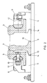
- FIG. 1 shows the detail of a plan view of a switch according to the invention with a centerpiece with a movable main and example tip; 2 shows a section along the line II-II of Figure 1, the tongue rail is shown in a different position, and Figure 3 shows a section along the line III-III of Figure 1.
- 1 denotes a frog, which has a frog tip 2 with a main tip 3 and an example 4.
- the wing rails of the centerpiece 1 are designated 5 and 6.
- the wing rails 5 and 6 are fixed to sleepers 7 by means of screws 8, as will be explained in more detail below.
- the foot 9 of the main tip 3 has, in the area of the fixing of the wing rail 5 on a threshold 7, recesses 10, the functioning of which will be explained in more detail below.
- the main tip 3 is shown in contact with the wing rail 5.
- the main tip is made of a thick web control rail profile, for example UIC60 according to UIC 861-3V but with 30 mm web thickness or UIC54 "Profile A” according to UIC 861-2V with 28 mm web thickness.
- the asymmetrical and lower height wing rail parts 5 and 6 are adapted to the rail profile used for the tip, for which purpose, for example, an asymmetrical tongue profile for UIC rail 60 kg / m according to UIC 861-2V or a "profile B 68.5 kg / m "according to UIC 861-2V can be used.
- the wing rails 5 and 6 are each fixed on base plates 11, the height of which is dimensioned such that the total height of the base plate 11 with the lower wing rail 5 or 6 corresponds to the height of the main tip 3.
- the wing rails 5 are fixed on the base plate 11 in a known manner via supports 12 which are connected to the wing rail by means of a screw connection 13 and to the base plate 11 by means of the screw connection 8.
- the base plates 11 have recesses 14 on their end faces facing the tip 3, into which recesses part 10 of the rail foot 9 of the tip 3 can engage in the position in contact with the wing rail. Overlapping of the base plate 11 in this way prevents the tip 3 from rising and the base plate 11 thus acts as a hold-down device in the position in contact with the wing rail.
- connection according to FIG. 3 shows the connection between the main tip 3 and the example tip 4.
- the example 4 like the main tip 3, is formed using thick-web control rail profiles, as explained above.
- the wing rails 5 and 6 in turn have a lower height and an asymmetrical tongue profile and are in turn fixed on base plates 11 on the sleepers 7.
- the main tip 3 and the example tip 4 are connected to one another by a screw connection 15, the opening 16 for the screw 15 in the example 4 is designed as an elongated hole running in the longitudinal direction of the rail profile.
- the screw is screwed together with a high-strength screw on the screw head and on the rail web of the main tip, while the tip is pressed against the main tip with spring elements.
- the opening in the main tip 3 is designed as a simple bore 17.
- the example tip 4 also has a rail foot 18 for a more stable design of the centerpiece with less risk of tipping.
- the transmission of lateral forces from the tips 3 and 4 to the respective wing rails 5 and 6 takes place via supports 19 and 20 which can be attached to the wing rail or to the apex of the heart. These supports are also indicated in Fig.1 and also designated 19 and 20 respectively.
- Spacers 21 which are indicated schematically in FIG. 1, are also provided for support between the main tip and the tip 3 at a large distance from the tip region. These spacers can alternately be attached on one side to the main and at the tip, so that the opposite contact surface on the thick bar control rail profile of the other tip can slide during the changeover due to the relative displacement between the main and the tip on the rail profile.
- main and example tips Due to the design of the main and example tips as a thick web control rail profile, these components are superior to known movable tips in terms of load capacity. Furthermore, by using such frogs, their overall length can be shortened considerably, since the relative displacement of the changeover process can be placed in the area between the main and the example, since the machined thick web profiles have a sufficient load-bearing capacity.
- thick web control profiles for the main and example 3 or 4 This can be designed to run continuously from the start of the tip to the end of the switch, so that during a changeover process, bending lines or running edge profiles are created which can be exactly predetermined.
- the main tip 3 and example 4 are thus continuous elastic switch elements without rigid interference areas.
- the use of a thick web control rail profile for the main tip 3 and example 4 makes it possible to keep spring points in the rail foot, which are not shown for the sake of clarity, relatively short and to be arranged relatively far forward without making the changeover forces unacceptably high. Such a shortening also has a favorable effect on the overall length of the centerpiece tip 2. Due to the elastic design of the entire centerpiece with thick web control rail profiles as tips 3 and 4 or asymmetrical profiles for the wing rails 5 and 6, the centerpiece fits into the elastic behavior of the track and does not represent a foreign body in the elastic track.
- the main tip 3 and example 4 from the thick web control rail profile are either guided to the end of the crosspiece tip 2 and adapted there to the control rail profile or they end in the clamped area 2 to 3 threshold fields before the end of the crosspiece and are welded to a control rail after adaptation to the control rail profile , which extends to the centerpiece.
- the wing rail parts designed as an asymmetrical tongue profile of low height in the area of the frog 1 are either forged in the area immediately in front of the tip of the heart from the lower asymmetrical tongue profile to the standard rail profile or mutually adapted and welded to a standard rail which extends to the beginning of the frog.
- the asymmetrical tongue profile can also extend to the beginning of the centerpiece and can only be adapted to the standard rail profile there.
- the wing rail parts are either guided up to the wing rail end as an asymmetrical tongue profile or after the overflow area behind the zone after the cardiac tips also forged onto the control rail profile or adapted to one another and welded to a control rail which extends to the end of the wing rail.
- either naturally hard untreated rail steels, special grade steels, heat-treated steels or hard manganese steel can be rolled or cast, which can also be pre-consolidated.
- the adjoining control rail which connects at the beginning or end of the heart or end of the wing rail, is connected to the respective road section of the centerpiece tip or the wing rail according to special methods for welding hard manganese steel to rail steel.
- a fastening can also be used, which is referred to as the inner stock rail bracing.
- the cardiac tips 3 and 4 can also be fastened in the clamped area and in the area of the wing rails made of standard rail profile by means of elastic clamping plates attached on the inside.
Landscapes
- Engineering & Computer Science (AREA)
- Mechanical Engineering (AREA)
- Architecture (AREA)
- Civil Engineering (AREA)
- Structural Engineering (AREA)
- Railway Tracks (AREA)
- Investigating Or Analysing Biological Materials (AREA)
- Gears, Cams (AREA)
- Sampling And Sample Adjustment (AREA)
- Harvester Elements (AREA)
- Toys (AREA)
- Percussion Or Vibration Massage (AREA)
- Thermotherapy And Cooling Therapy Devices (AREA)
- Mutual Connection Of Rods And Tubes (AREA)
- Machines For Laying And Maintaining Railways (AREA)
- Adjustable Resistors (AREA)
- Escalators And Moving Walkways (AREA)
- Train Traffic Observation, Control, And Security (AREA)
- Passenger Equipment (AREA)
- Finger-Pressure Massage (AREA)
- Massaging Devices (AREA)
- Pens And Brushes (AREA)
- Mechanical Pencils And Projecting And Retracting Systems Therefor, And Multi-System Writing Instruments (AREA)
- Keying Circuit Devices (AREA)
- Switches With Compound Operations (AREA)
- Preliminary Treatment Of Fibers (AREA)
Abstract
Description
Die Erfindung bezieht sich auf eine Weiche mit einem Herzstück mit beweglicher Haupt- und Beispitze.The invention relates to a switch with a centerpiece with a movable main and example.
Herzstücke mit beweglicher Herzstückspitze, die eine Hauptspitze und eine gleitend an der Hauptspitze anliegende Beispitze aufweisen, sind beispielsweise aus dem Deutschen Gebrauchsmuster 69 08 819 (DE-B-1911 160) bekanntgeworden. Um die geforderte Flexibilität sicherzustellen, sind bei derartigen Ausbildungen große Baulängen erforderlich und die bisher bekannten Ausbildungen weisen eine relativ geringe Tragfähigkeit und Standfestigkeit der Spitze auf. Es mußten daher in der Regel Einschränkungen im Bezug auf die Verwendung von Werkstoffen oder auch bei der Anwendung für verschiedene Weichengeometrien hingenommen werden und ein weiterer Nachteil bekannter Ausbildungen bestand darin, daß Schweiß- und Klebestöße in der Fahrbahn zum Teil im nicht eingespannten Bereich erforderlich waren. Ein zusätzliches Problem bei den bekannten Ausbildungen ist die Fehleranfälligkeit im Fahrkantenverlauf und für bisher bekannte bewegliche Spitzen wurde eine relativ komplizierte konstruktive Durchbildung und ein kompliziertes Verschlußsystem erforderlich.Frogs with a movable frog tip, which have a main tip and an example that slidably abuts the main tip, have become known, for example, from German Utility Model 69 08 819 (DE-B-1911 160). In order to ensure the required flexibility, large lengths are required for such designs and the previously known designs have a relatively low load-bearing capacity and stability of the tip. As a rule, restrictions had to be accepted with regard to the use of materials or also for the use of different switch geometries, and a further disadvantage of known designs was that welding and adhesive shocks in the carriageway were sometimes required in the unclamped area. An additional problem with the known designs is the susceptibility to errors in the running edge course and a relatively complicated design and a complicated locking system was required for previously known movable tips.
Die Erfindung zielt nun darauf ab, eine Weiche der eingangs genannten Art mit einem beweglichen Herzstück zu schaffen, bei welcher im Schienen- und Weichenbau übliche Werkstoffe uneingeschränkt Verwendung finden können und welche sich durch größere Tragfähigkeit und Standfestigkeit, insbesondere im Spitzenbereich, auszeichnet. Zur Lösung dieser Aufgabe besteht die erfindungsgemäße Weiche im wesentlichen darin, daß die Haupt- und Beispitze unter Verwendung von Dicksteg-Regelschienenprofilen ausgebildet sind und daß als äußere Flügelschienen gegenüber den Dicksteg-Regelschienenprofilen niedrigere, wenigstens teilweise auf Unterlagsplatten festgelegte, asymmetrische Zungenprofile angeordnet sind. Durch die Verwendung von Dicksteg-Regelschienenprofilen kann sowohl für Haupt- und Beispitze gleiches Material gewählt werden, so daß ein gleichmäßiger Verschleiß und damit ein geringerer Wartungsaufwand erzielt wird. Die Wahl von Dicksteg-Regelschienenprofilen verleiht hiebei der Haupt- und Beispitze die erforderliche Stabilität bei gleichzeitiger Verbesserung der Möglichkeit der elastischen Abspannung der Flügelschienenteile und durch die Maßnahme, die äußeren Flügelschienen gegenüber den Dicksteg-Regelschienenprofilen des Herzstückes niedriger auszubilden und wenigstens teilweise auf Unterlagsplatten festzulegen, wird die Möglichkeit geschaffen, daß die Dicksteg-Regelschienenprofile bei einem Verschwenken der Herzspitze mit ihrem Fußteil unterhalb der Flügelschienen gegen Aufsteigen gesichert werden können. Es wird somit durch die Dicksteg-Regelschienenprofile der Herzspitze die erforderliche Festigkeit gewährleistet und durch die spezielle Ausbildung der äußeren Flügelschienen ein Aufsteigen der Herzstückspitze sicher verhindert. Eine derartige Ausbildung ist insbesondere für Hochgeschwindigkeitsweichen von besonderem Vorteil, bei welchen bei Einsatz unterschiedlicher Materialien, wie beispielsweise Mangan-Hartstahlguß, die erforderlichen Stöße bzw. Fahrbahnverbindungen nicht ohne hohen Aufwand herstellbar sind. Dadurch, daß ein relativ starrer und nicht flexibler Block bei der erfindungsgemäßen Konstruktion vermieden wird, kann ein exakterer Fahrkantenverlauf nach Abschluß des Umstellvorganges erzielt werden, was insbesondere bei hohen und Höchstgeschwindigkeiten von besonderer Bedeutung ist. Eine Verbesserung des exakten Fahrkantenverlaufes kann zwar prinzipiell durch die Unterteilung des Herzstückes in Haupt- und Beispitze besser gelöst werden, jedoch haben die bisher bekannten Vorschläge hiebei den Einsatz von Zungenprofilen vorgesehen, welche dann die Gefahr mit sich bringen, daß die niedereren und mechanisch stark bearbeiteten Spitzen bezüglich ihrer Tragfähigkeit überbeansprucht werden. Die Spitzen aus Zungenprofilen müssen im vorderen Bereich mechanisch bearbeitet werden und die an sich schwachen Profile werden dabei geschwächt.The invention now aims to provide a switch of the type mentioned with a movable centerpiece, in which common materials can be used without restrictions in rail and switch construction and which is characterized by greater load-bearing capacity and stability, especially in the tip area. To achieve this object, the switch according to the invention essentially consists in the fact that the main and exemplary tips are formed using thick web control rail profiles and that lower outer rails compared to the thick web control rail profiles are lower, at least partially fixed on base plates, asymmetrical tongue profiles are arranged. Through the use of thick web control rail profiles, the same material can be selected for both the main and the example, so that uniform wear and thus less maintenance is achieved. The choice of thick web control rail profiles gives the main and example the necessary stability while simultaneously improving the possibility of elastic bracing of the wing rail parts and by the measure of making the outer wing rails lower than the thick web control rail profiles of the centerpiece and at least partially fixing them on base plates. the possibility is created that the Dicksteg control rail profiles can be secured against rising when the tip of the heart is pivoted with its foot part below the wing rails. The required strength is ensured by the thick web control rail profiles of the heart tip and the special design of the outer wing rails prevents the tip of the heart from rising. Such a design is particularly advantageous for high-speed switches, in which the required joints or road connections cannot be produced without great effort when using different materials, such as manganese hard steel castings. Because a relatively rigid and inflexible block is avoided in the construction according to the invention, a more precise running edge course can be achieved after the changeover process has been completed, which is particularly important at high and maximum speeds. An improvement in the exact running edge course can in principle be better solved by dividing the heart into the main and bypass, but the previously known proposals have provided the use of tongue profiles, which then entail the risk that the lower and mechanically heavily machined Tips are overstressed with regard to their load-bearing capacity. The tips made of tongue profiles must are machined in the front area and the weak profiles are weakened.
Um die Gefahr des Aufsteigens der auf Grund der Dicksteg-Regelschienenprofile ohnedies schon stabileren Herzstückspitze noch weiter zu mindern, ist mit Vorteil die Ausbildung so getroffen, daß die Höhe der niedrigeren asymmetrischen Zungenprofile um wenigstens die Höhe des Schienenfußes der Dicksteg-Regelschienenprofile der Herzstückspitze geringer ist als die Höhe der Dicksteg-Regelschienenprofile der Herzstückspitze. Auf diese Weise kann die Herzstückspitze in der jeweiligen Endlage mit dem Fußteil des Dicksteg-Regelschienenprofiles unterhalb die äußeren Flügelschienen eingeschoben werden, wodurch eine Verriegelung erzielt wird. Mit Vorteil ist die Ausbildung hiebei so getroffen, daß die der Herzstückspitze zugewandten Stirnseiten der Unterlagsplatten Ausnehmungen für das Übergreifen des Fußes der Herzstückspitze in anliegender Stellung der Herzstückspitze aufweisen.In order to further reduce the risk of rising of the frog tip, which is already more stable due to the thick web control rail profiles, the design is advantageously made such that the height of the lower asymmetrical tongue profiles is lower by at least the height of the rail foot of the thick web control rail profiles of the frog tip than the height of the thick web control rail profiles of the frog tip. In this way, the centerpiece tip can be inserted in the respective end position with the foot part of the thick web control rail profile below the outer wing rails, whereby a locking is achieved. The design is advantageously made such that the end faces of the base plates facing the frog tip have recesses for engaging over the foot of the frog tip in the abutting position of the frog tip.
Um in denjenigen Bereichen, in welchen eine derartige Abstützung gegen Aufsteigen nicht ohne weiteres realisiert werden kann, die Stabilität nicht zu beeinträchtigen und um gleichzeitig die Flexibilität der Herzstückspitze zu erhöhen, ist mit Vorteil die Ausbildung so getroffen, daß der Fuß der Herzstückspitze im Bereich zumindest eines Teiles der Unterlagsplatten der Flügelschienen auf geringere Breite ausgenommen ausgebildet ist.In order not to impair the stability in those areas in which such support against ascent cannot readily be achieved and at the same time to increase the flexibility of the frog tip, the design is advantageously made such that the foot of the frog tip in the area at least part of the base plates of the wing rails is formed except for a smaller width.
Die Verwendung von Dicksteg-Regelschienenprofilen für Haupt-und Beispitze ermöglicht nun aber auch eine besonders stabile gleitende Festlegung der Beispitze an der Hauptspitze im Auslaufbereich des Herzstückes. Um hier die Flexibilität zu erhöhen, ist mit Vorteil an dieser Stelle eine Gleitverbindung vorgesehen und die Ausbildung kann in besonders einfacher Weise so getroffen werden, daß die Hauptspitze und die Beispitze durch ihre aneinander anliegenden Flächen hindurch miteinander verschraubt sind und daß die Durchbrechung für die insbesondere mit einer Abstützhülse und Federelementen versehenen Schraube in der Haupt- und/oder Beispitze als in Längsrichtung des Schienenprofiles verlaufendes Langloch ausgebildet ist. Da für Haupt- und Beispitze Dicksteg-Regelschienenprofile verwendet wurden, kann eine derartige durch Langlöcher auftretende Schwächung des Profiles ohne weiteres in Kauf genommen werden, ohne daß die Stabilität in unzulässiger Weise beeinträchtigt wird. Insgesamt ergibt sich durch diese Maßnahme im Bereich der Herzstückspitze ein besonders exakter Fahrkantenverlauf, welcher ein derartiges Herzstück für den Einsatz in Hochgeschwindigkeitsweichen besonders geeignet macht.However, the use of thick web control rail profiles for the main and the tip now also enables a particularly stable sliding fixing of the tip at the main tip in the outlet area of the frog. In order to increase flexibility here, a sliding connection is advantageously provided at this point and the design can be made in a particularly simple manner in such a way that the main tip and the tip point through their abutting surfaces are screwed together and that the opening for the screw, in particular provided with a support sleeve and spring elements, is formed in the main and / or example as an elongated hole extending in the longitudinal direction of the rail profile. Since thick-bar control rail profiles were used for the main and example, such weakening of the profile due to elongated holes can be readily accepted without the stability being impaired in an impermissible manner. Overall, this measure results in a particularly exact running edge course in the area of the centerpiece tip, which makes such a centerpiece particularly suitable for use in high-speed switches.
Die Erfindung wird nachfolgend and Hand eines in der Zeichnung dargestellten Ausführungsbeipieles näher erläutert. In dieser zeigen: Fig.1 den Ausschnitt eine Draufsicht auf eine erfindungsgemäße Weiche mit einem Herzstück mit beweglicher Haupt- und Beispitze; Fig.2 einen Schnitt nach der Linie II-II der Fig.1, wobei die Zungenschiene in einer anderen Stellung gezeigt ist, und Fig.3 eine Schnitt nach der Linie III-III der Fig.1.The invention is explained in more detail below using an exemplary embodiment shown in the drawing. 1 shows the detail of a plan view of a switch according to the invention with a centerpiece with a movable main and example tip; 2 shows a section along the line II-II of Figure 1, the tongue rail is shown in a different position, and Figure 3 shows a section along the line III-III of Figure 1.
In Fig.1 ist mit 1 ein Herzstück bezeichnet, welches eine Herzstückspitze 2 mit einer Hauptspitze 3 und einer Beispitze 4 aufweist. Die Flügelschienen des Herzstückes 1 sind mit 5 und 6 bezeichnet. Die Festlegung der Flügelschienen 5 und 6 auf Schwellen 7 erfolgt mittels Schrauben 8, wie dies im folgenden noch näher erläutert werden wird. Der Fuß 9 der Hauptspitze 3 weist teilweise im Bereich der Festlegung der Flügelschiene 5 auf einer Schwelle 7 Ausnehmungen 10 auf, deren Funktionsweise weiter unten näher erläutert werden wird.In FIG. 1, 1 denotes a frog, which has a frog tip 2 with a
In Fig.2 ist die Hauptspitze 3 in Anlage an die Flügelschiene 5 dargestellt. Die Hauptspitze ist dabei aus einem Dicksteg-Regelschienenprofil, beispielsweise UIC60 nach UIC 861-3V jedoch mit 30 mm Stegdicke oder UIC54 "Profil A" nach UIC 861-2V mit 28 mm Stegdicke, ausgebildet. Auch die asymmetrisch und mit geringerer Höhe ausgebildeten Flügelschienenteile 5 und 6 sind dem verwendeten Schienenprofil für die Spitze angepaßt, wofür beispielsweise ein asymmetrisches Zungenprofil für UIC-Schiene 60 kg/m nach UIC 861-2V oder ein "Profil B 68,5 kg/m" nach UIC 861-2V Verwendung finden kann. Die Flügelschienen 5 und 6 sind jeweils auf Unterlagsplatten 11 festgelegt, deren Höhe so bemessen ist, daß die Gesamthöhe der Unterlagsplatte 11 mit der niedriger ausgebildeten Flügelschiene 5 bzw. 6 jeweils der Höhe der Hauptspitze 3 entspricht. Die Festlegung der Flügelschienen 5 auf der Unterlagsplatte 11 erfolgt dabei in bekannter Weise über Abstützungen 12, welche mittels einer Verschraubung 13 mit der Flügelschiene und mittels der Verschraubung 8 mit der Unterlagsplatte 11 verbunden ist. Die Unterlagsplatten 11 weisen an ihren der Spitze 3 zugewandten Stirnflächen Ausnehmungen 14 auf, in welche der abgesetzt ausgebildete Teil 10 des Schienenfußes 9 der Spitze 3 in an die Flügelschiene anliegender Stellung eingreifen kann. Durch ein derartiges Übergreifen der Unterlagsplatte 11 wird ein Aufsteigen der Spitze 3 vermieden und es wirkt die Unterlagsplatte 11 somit als Niederhalter in an die Flügelschiene anliegender Stellung.In Figure 2, the
In der Darstellung gemäß Fig.3 ist die Verbindung der Hauptspitze 3 mit der Beispitze 4 näher dargestellt. Die Beispitze 4 ist ebenso wie die Hauptspitze 3 unter Verwendung von Dicksteg-Regelschienenprofilen, wie oben erläutert, ausgebildet. Die Flügelschienen 5 und 6 weisen wiederum eine geringere Höhe und ein asymmetrisches Zungenprofil auf und sind auf Unterlagsplatten 11 wiederum an den Schwellen 7 festgelegt. Wie aus Fig.3 ersichtlich, sind die Hauptspitze 3 und die Beispitze 4 durch eine Verschraubung 15 miteinander verbunden, wobei die Durchbrechung 16 für die Schraube 15 in der Beispitze 4 als in Längsrichtung des Schienenprofiles verlaufendes Langloch ausgebildet ist. Um eine Relativverschiebung zwischen Hauptspitze und Beispitze zu ermöglichen, ist die Schraube mit einer am Schraubenkopf und am Schienensteg der Hauptspitze anliegenden Hülse hochfest verschraubt, während die Beispitze mit Federelementen an die Hauptspitze angedrückt wird. Die Durchbrechung in der Hauptspitze 3 ist als einfache Bohrung 17 ausgebildet. Ebenso wie die Hauptspitze weist auch die Beispitze 4 einen Schienenfuß 18 für eine stabilere Ausbildung des Herzstückes bei geringerer Kippgefahr auf. Die Übertragung von Seitenkräften von den Spitzen 3 und 4 auf die jeweiligen Flügelschienen 5 bzw. 6 erfolgt über Stützen 19 und 20, welche an der Flügelschiene bzw. an der Herzspitze befestigt werden können. Diese Stützen sind auch in Fig.1 angedeutet und ebenfalls mit 19 bzw. 20 bezeichnet.The connection according to FIG. 3 shows the connection between the
Zur Abstützung zwischen Haupt- und Beispitze 3 in einem großen Abstand von dem Spitzenbereich sind weiters Distanzstücke 21 vorgesehen, welche in Fig.1 schematisch angedeutet sind. Diese Distanzstücke können dabei abwechselnd einseitig an der Haupt- und an der Beispitze befestigt werden, so daß die jeweils gegenüberliegende Anlagefläche an dem Dicksteg-Regelschienenprofil der anderen Spitze bei der Umstellung durch die Relativverschiebung zwischen Haupt- und Beispitze am Schienenprofil gleiten kann.
Durch die Ausbildung der Haupt- und Beispitzen als Dicksteg-Regelschienenprofil sind diese Bauelemente bekannten beweglichen Spitzen in der Tragkraft überlegen. Weiters kann durch die Verwendung derartiger Herzstücke deren Baulänge wesentlich verkürzt werden, da die Relativverschiebung des Umstellvorganges in dem Bereich zwischen Haupt- und Beispitze gelegt werden kann, da eine ausreichende Tragkraft der bearbeiteten Dicksteg-Profile vorhanden ist. Durch die Verwendung von Dicksteg-Regelprofilen für die Haupt- und Beispitze 3 bzw. 4 kann dieses durchgehend vom Beginn der Spitze bis zum Weichenende verlaufend ausgebildet sein, so daß bei einem Umstellvorgang Biegelinien bzw. Fahrkantenverläufe entstehen, die exakt vorherbestimmbar sind. Die Hauptspitze 3 und Beispitze 4 sind somit kontinuierliche elastische Weichenelemente ohne starre Störungsbereiche. Weiters wird es durch die Verwendung von Dicksteg-Regelschienenprofil für die Hauptspitze 3 und Beispitze 4 möglich, Federstellen im Schienenfuß, welche der Deutlichkeit halber nicht dargestellt sind, relativ kurz zu halten und relativ weit vorne anzuordnen, ohne die Umstellkräfte unzulässig hoch werden zu lassen. Eine derartige Verkürzung wirkt weiters günstig auf die gesamte Baulänge der Herzstückspitze 2. Durch die elastische Ausbildung des kompletten Herzstückes mit Dicksteg-Regelschienenprofilen als Spitzen 3 und 4 bzw. asymmetrische Profile für die Flügelschienen 5 und 6 fügt sich das Herzstück in das elastische Verhalten des Gleises ein und stellt keinen Fremdkörper im elastischen Gleis dar.Due to the design of the main and example tips as a thick web control rail profile, these components are superior to known movable tips in terms of load capacity. Furthermore, by using such frogs, their overall length can be shortened considerably, since the relative displacement of the changeover process can be placed in the area between the main and the example, since the machined thick web profiles have a sufficient load-bearing capacity. By using thick web control profiles for the main and example 3 or 4 This can be designed to run continuously from the start of the tip to the end of the switch, so that during a changeover process, bending lines or running edge profiles are created which can be exactly predetermined. The
Die Hauptspitze 3 und Beispitze 4 aus dem Dicksteg-Regelschienenprofil werden entweder bis an das Ende der Herzstückspitze 2 geführt und dort dem Regelschienenprofil angepaßt oder sie enden im eingespannten Bereich 2 bis 3 Schwellenfelder vor dem Herzstückende und werden nach Anpassung an das Regelschienenprofil mit einer Regelschiene verschweißt, welche bis zum Herzstückende reicht. Die als asymmetrisches Zungenprofil geringer Höhe ausgebildeten Flügelschienenteile im Bereich des Herzstückes 1 werden entweder im Bereich unmittelbar vor der Herzspitze vom niederen asymmetrischen Zungenprofil auf das Regelschienenprofil ausgeschmiedet oder gegenseitig angepaßt und mit einer Regelschiene verschweißt, welche bis zum Herzstückbeginn reicht. Das asymmetrische Zungenprofil kann jedoch auch bis zum Herzstückbeginn reichen und erst dort dem Regelschienenprofil angepaßt werden. Weiters werden die Flügelschienenteile entweder bis zum Flügelschienenende als asymmetrisches Zungenprofil geführt oder nach dem Überlaufbereich hinter der Zone nach den Herzspitzen ebenfalls auf das Regelschienenprofil ausgeschmiedet oder gegenseitig angepaßt und mit einer Regelschiene verschweißt, die bis an das Flügelschienenende reicht.The
Für die Haupt- und Beispitzenabschnitte aus dem Dicksteg-Regelschienenprofil und für die Flügelschienenabschnitte aus dem niedrigen asymmetrischen Zungenschienenprofil können entweder naturharte unbehandelte Schienenstähle, Sondergütenstähle, wärmebehandelte Stähle oder Hartmangan-Stahl gewalzt oder gegossen verwendet werden, welcher auch vorverfestigt werden kann. Im Fall von Hartmangan-Stahl wird die anschließende Regelschiene, welche am Herzbeginn oder Herzende bzw. Flügelschienenende anschließt, an den jeweiligen Fahrbahnteil der Herzstückspitze bzw. der Flügelschiene entsprechend speziellen Verfahren für ein Verschweißen von Hartmangan-Stahl mit Schienenstahl verbunden.For the main and example sections from the thick web standard rail profile and for the wing rail sections from the low asymmetrical tongue rail profile, either naturally hard untreated rail steels, special grade steels, heat-treated steels or hard manganese steel can be rolled or cast, which can also be pre-consolidated. In the case of hard manganese steel, the adjoining control rail, which connects at the beginning or end of the heart or end of the wing rail, is connected to the respective road section of the centerpiece tip or the wing rail according to special methods for welding hard manganese steel to rail steel.
Anstelle der in den Figuren dargestellten Festlegung der Dicksteg-Regelschienenprofile kann auch eine Befestigung verwendet werden, welche als innere Backenschienenverspannung bezeichnet wird. Die Herzspitzen 3 und 4 können auch im eingespannten Bereich und im Bereich der Flügelschienen aus Regelschienenprofil durch innen angebrachte elastische Klemmplatten befestigt werden.Instead of the determination of the thick web control rail profiles shown in the figures, a fastening can also be used, which is referred to as the inner stock rail bracing. The
Claims (5)
- Switch having a crossing with a movable main nose and secondary nose (3, 4), the secondary nose (4) resting in a sliding manner on the main nose (3), characterised in that the main nose and secondary nose (3, 4) are constructed using thick web standard rail profiles, and in that asymmetrical tongue profiles, which are lower relative to the thick web standard rail profiles and are fixed at least partially on bearing plates (11), are arranged as outer wing rails (5, 6).
- Switch according to Claim 1, characterised in that the height of the lower, asymmetrical tongue profiles (5, 6) is less than the height of the thick web standard rail profiles of the crossing nose (3, 4) by at least the height of the rail foot (9, 18) of the thick web standard rail profiles of the crossing nose (3, 4).
- Switch according to Claim 1 or 2, characterised in that the end faces of the bearing plates (11) facing the crossing nose (3, 4) have recesses (14) for gripping over the foot (9, 18) of the crossing nose (3, 4) in the resting position of the crossing nose.
- Switch according to Claim 1, 2 or 3, characterised in that the foot (9, 18) of the crossing nose (3, 4) is constructed so as to be recessed to a lesser width in the region (10) of at least part of the bearing plates (11) of the wing rails (5, 6).
- Switch according to one of Claims 1 to 4, characterised in that the main nose (3) and the secondary nose (4) are screwed to one another through their mutually adjacent surfaces, and in that the opening (16, 17) in the main nose and/or secondary nose (3, 4) for the screw (15), provided in particular with a support sleeve and spring elements, is constructed as an elongate hole running in the longitudinal direction of the rail profile.
Applications Claiming Priority (2)
| Application Number | Priority Date | Filing Date | Title |
|---|---|---|---|
| AT1340/88 | 1988-05-20 | ||
| AT0134088A AT390084B (en) | 1988-05-20 | 1988-05-20 | SOFT WITH A HEART PIECE WITH A MOVABLE MAIN AND EXTRA TIP |
Publications (3)
| Publication Number | Publication Date |
|---|---|
| EP0343150A2 EP0343150A2 (en) | 1989-11-23 |
| EP0343150A3 EP0343150A3 (en) | 1990-06-13 |
| EP0343150B1 true EP0343150B1 (en) | 1992-12-30 |
Family
ID=3511783
Family Applications (1)
| Application Number | Title | Priority Date | Filing Date |
|---|---|---|---|
| EP89890147A Expired - Lifetime EP0343150B1 (en) | 1988-05-20 | 1989-05-18 | Switch including a frog comprising a principal and a secondary movable tongue |
Country Status (10)
| Country | Link |
|---|---|
| US (1) | US4953814A (en) |
| EP (1) | EP0343150B1 (en) |
| AT (2) | AT390084B (en) |
| CA (1) | CA1323013C (en) |
| DE (1) | DE58903144D1 (en) |
| ES (1) | ES2038001T3 (en) |
| FI (1) | FI92504C (en) |
| GR (1) | GR3007447T3 (en) |
| NO (1) | NO173748C (en) |
| SU (1) | SU1724020A3 (en) |
Families Citing this family (24)
| Publication number | Priority date | Publication date | Assignee | Title |
|---|---|---|---|---|
| DE3828921C3 (en) * | 1988-08-26 | 2000-10-26 | Weichenbau Laeis Gmbh & Co Kg | Process for producing a switch with a centerpiece with a spring-loaded tip and a switch with a centerpiece |
| CA1324364C (en) * | 1988-10-14 | 1993-11-16 | Gerard Testart | Movable tip frog and fabrication process thereof |
| LU87721A1 (en) * | 1990-04-11 | 1990-12-11 | Kihn Sarl | THREAD RAIL NEEDLE |
| DE4014346C2 (en) * | 1990-05-04 | 2002-03-21 | Butzbacher Weichenbau Gmbh | Centerpiece tip adjustable relative to wing rails |
| FR2662450B1 (en) * | 1990-05-23 | 1992-09-11 | Cogifer | SWITCHING FOR ROUTES OF GUIDE. |
| FR2672316B1 (en) * | 1991-02-05 | 1993-05-28 | Cogifer Cie Cle Installat Ferr | TRACK APPARATUS FOR RAIL VEHICLES ON TIRES WITH MEDIAN GUIDING ROLLER AND METHOD FOR MANUFACTURING SAME. |
| FR2695662B1 (en) * | 1992-09-11 | 1994-11-18 | Cogifer | Embedding of the movable point in the cradle of a crossing core incorporated in the long welded rails and method of producing such embedding. |
| DE4412806A1 (en) * | 1994-04-14 | 1994-09-01 | Guenter Andres | Track points (switch) for railway and rail traffic |
| AU4206397A (en) * | 1996-08-21 | 1998-03-06 | Hubmann, Hans-Peter | Crossing assembly for point switches and processing |
| DE19901949C2 (en) * | 1999-01-20 | 2002-10-31 | Thyssen Krupp Materials & Serv | Movable two-piece or multi-piece centerpiece tip |
| US6286791B1 (en) * | 2000-03-09 | 2001-09-11 | Abc-Naco Inc. | Railroad spring wing frog with hold-open and shock dampening elements |
| DE10310043A1 (en) * | 2003-03-06 | 2004-09-16 | Schreck-Mieves Gmbh | heart |
| AT506269B1 (en) * | 2008-01-14 | 2010-02-15 | Vae Eisenbahnsysteme Gmbh | SOFT WITH MOBILE HEARTSTICK TIP |
| RU2369676C1 (en) * | 2008-02-15 | 2009-10-10 | Государственное образовательное учреждение высшего профессионального образования "Петербургский государственный университет путей сообщения" | Stub switch |
| ES1072245Y (en) * | 2010-04-09 | 2010-09-09 | Amurrio Ferrocarril Y Equipos | ENCLOSURE DEVICE FOR HEART OF PUNTA MOVIL |
| ES2399735B1 (en) * | 2010-06-15 | 2013-11-13 | Jez Sistemas Ferroviarios, S.L. | ACUTE HEART OF MOBILE POINT FOR DEVICES OF VIA DE CARRIL GARGANTA |
| EP2479080A3 (en) * | 2011-01-19 | 2015-10-28 | Siemens Schweiz AG | Clamp lock with lock clamp screw |
| US8424812B1 (en) | 2011-01-25 | 2013-04-23 | Cleveland Track Material, Inc. | Elevated frog and rail track assembly |
| EP2487293B1 (en) * | 2011-02-08 | 2014-05-07 | Jez Sistemas Ferroviarios, S.l. | Acute swing nose crossing for railways |
| US8556217B1 (en) | 2011-05-24 | 2013-10-15 | Cleveland Track Material, Inc. | Elevated frog and rail crossing track assembly |
| AT513323B1 (en) | 2012-08-28 | 2014-08-15 | Voestalpine Hytronics Gmbh | Switch for rails |
| DE102012017982A1 (en) * | 2012-09-12 | 2014-03-13 | Schwihag Ag | Heart rolling device |
| CN115748315B (en) * | 2022-11-25 | 2025-08-01 | 中铁宝桥集团有限公司 | Wing rail reinforced type combined frog |
| US20240392512A1 (en) * | 2023-05-26 | 2024-11-28 | voestalpine Railway Systems Nortrak LLC | Moveable Point Frog Friction-Reducing Assembly |
Family Cites Families (11)
| Publication number | Priority date | Publication date | Assignee | Title |
|---|---|---|---|---|
| US487957A (en) * | 1892-12-13 | Railroad-frog | ||
| DE211594C (en) * | ||||
| DE488452C (en) * | 1928-10-05 | 1930-01-06 | Fried Krupp Akt Ges | Simple heart |
| US2377273A (en) * | 1942-07-29 | 1945-05-29 | George J H Siebert | Railway track assembly |
| FR1547338A (en) * | 1966-12-21 | 1968-11-22 | Kloeckner Werke Ag | Single heart point with elastic point |
| AT288463B (en) * | 1967-02-17 | 1971-03-10 | Oeesterreichisch Alpine Montan | Turnout centerpiece |
| DE6908819U (en) * | 1969-03-05 | 1974-06-06 | Krupp Ag Huettenwerke | HEART PIECE WITH MOVABLE HEART PIECE TIP. |
| DE1911160B1 (en) * | 1969-03-05 | 1970-07-16 | Krupp Ag Huettenwerke | Heart piece with movable heart piece tip |
| FR2339706A1 (en) * | 1976-02-02 | 1977-08-26 | Abbaye Atel Const | Rail track points for crane support - have blade sliding on straight line at right angles to track direction |
| FR2551106B1 (en) * | 1983-03-30 | 1985-12-06 | Renaud Christian | SLIDING BEARING NEEDLE FIXING APPARATUS FOR RAILWAY ROUTING |
| DE3411122A1 (en) * | 1984-03-26 | 1985-10-03 | BWG Butzbacher Weichenbau GmbH, 6308 Butzbach | DEVICE FOR FIXING RAILS |
-
1988
- 1988-05-20 AT AT0134088A patent/AT390084B/en not_active IP Right Cessation
-
1989
- 1989-05-17 SU SU894614008A patent/SU1724020A3/en active
- 1989-05-17 US US07/353,022 patent/US4953814A/en not_active Expired - Lifetime
- 1989-05-18 DE DE8989890147T patent/DE58903144D1/en not_active Expired - Fee Related
- 1989-05-18 EP EP89890147A patent/EP0343150B1/en not_active Expired - Lifetime
- 1989-05-18 AT AT89890147T patent/ATE84089T1/en not_active IP Right Cessation
- 1989-05-18 ES ES198989890147T patent/ES2038001T3/en not_active Expired - Lifetime
- 1989-05-19 CA CA000600214A patent/CA1323013C/en not_active Expired - Fee Related
- 1989-05-19 FI FI892447A patent/FI92504C/en not_active IP Right Cessation
- 1989-05-19 NO NO892031A patent/NO173748C/en not_active IP Right Cessation
-
1993
- 1993-03-23 GR GR930400634T patent/GR3007447T3/el unknown
Also Published As
| Publication number | Publication date |
|---|---|
| FI92504C (en) | 1994-11-25 |
| SU1724020A3 (en) | 1992-03-30 |
| GR3007447T3 (en) | 1993-07-30 |
| US4953814A (en) | 1990-09-04 |
| DE58903144D1 (en) | 1993-02-11 |
| AT390084B (en) | 1990-03-12 |
| EP0343150A3 (en) | 1990-06-13 |
| NO173748B (en) | 1993-10-18 |
| ATE84089T1 (en) | 1993-01-15 |
| FI892447A0 (en) | 1989-05-19 |
| FI892447L (en) | 1989-11-21 |
| ES2038001T3 (en) | 1993-07-01 |
| NO892031L (en) | 1989-11-21 |
| CA1323013C (en) | 1993-10-12 |
| NO892031D0 (en) | 1989-05-19 |
| ATA134088A (en) | 1989-08-15 |
| NO173748C (en) | 1994-01-26 |
| EP0343150A2 (en) | 1989-11-23 |
| FI92504B (en) | 1994-08-15 |
Similar Documents
| Publication | Publication Date | Title |
|---|---|---|
| EP0343150B1 (en) | Switch including a frog comprising a principal and a secondary movable tongue | |
| DE3339442C1 (en) | Heart piece for switches or crossings and method for producing such a heart piece | |
| DE4011523C2 (en) | Process for the production of profile bodies for switches for grooved rails by machining for the production of switches | |
| AT6220U2 (en) | TAMPING UNIT TO PUSH A TRACK | |
| DE3941937C2 (en) | ||
| DE2508739B2 (en) | ARTICULATED RAIL CONNECTION FOR A MON-RAIL TRACK IN MINING | |
| DE102016120200A1 (en) | Wing rail of a frog and method of manufacturing a frog | |
| DD289568A5 (en) | HEART PIECE WITH HEART TIP OF CASTED HARDMAN STEEL | |
| EP0295237A2 (en) | Switch operation device | |
| DE2922862A1 (en) | HEART PIECE FOR SOFT | |
| WO2004003295A1 (en) | Points comprising a reinforced switch tongue blade | |
| DE29602463U1 (en) | Two-block threshold | |
| DE8105454U1 (en) | "HEART PIECE" | |
| DE1048938B (en) | Spring tongue device, especially for grooved rail switches, in block construction | |
| AT506269B1 (en) | SOFT WITH MOBILE HEARTSTICK TIP | |
| DE2831285C2 (en) | Running rail made from a double T profile for an overhead monorail | |
| DE1284439B (en) | Heart piece with a block-like heart piece tip | |
| DE1658316B1 (en) | Simple centerpiece for switches and crossings | |
| EP3284863B1 (en) | Tongue rail and tongue device | |
| DE2061264A1 (en) | Heart for switches and crossings | |
| DE3521673A1 (en) | Device for fastening rails of a railway on steel sleepers, in particular on Y-type steel sleepers | |
| EP0315619A2 (en) | Switching apparatus for rocking rails or movable frogs in the crossing region of a point | |
| LU81085A1 (en) | FASTENING SYSTEM SUITABLE FOR FASTENING RAILWAY RAILS ON STEEL SLEEPERS | |
| DD285390A5 (en) | Herzstueck | |
| DE2429921C3 (en) | Centerpiece |
Legal Events
| Date | Code | Title | Description |
|---|---|---|---|
| PUAI | Public reference made under article 153(3) epc to a published international application that has entered the european phase |
Free format text: ORIGINAL CODE: 0009012 |
|
| AK | Designated contracting states |
Kind code of ref document: A2 Designated state(s): AT BE CH DE ES FR GB GR IT LI LU NL SE |
|
| PUAL | Search report despatched |
Free format text: ORIGINAL CODE: 0009013 |
|
| AK | Designated contracting states |
Kind code of ref document: A3 Designated state(s): AT BE CH DE ES FR GB GR IT LI LU NL SE |
|
| 17P | Request for examination filed |
Effective date: 19900828 |
|
| 17Q | First examination report despatched |
Effective date: 19910729 |
|
| RAP1 | Party data changed (applicant data changed or rights of an application transferred) |
Owner name: VOEST-ALPINE EISENBAHNSYSTEME GESELLSCHAFT M.B.H. |
|
| GRAA | (expected) grant |
Free format text: ORIGINAL CODE: 0009210 |
|
| AK | Designated contracting states |
Kind code of ref document: B1 Designated state(s): AT BE CH DE ES FR GB GR IT LI LU NL SE |
|
| REF | Corresponds to: |
Ref document number: 84089 Country of ref document: AT Date of ref document: 19930115 Kind code of ref document: T |
|
| REF | Corresponds to: |
Ref document number: 58903144 Country of ref document: DE Date of ref document: 19930211 |
|
| ITF | It: translation for a ep patent filed | ||
| GBT | Gb: translation of ep patent filed (gb section 77(6)(a)/1977) |
Effective date: 19930330 |
|
| ET | Fr: translation filed | ||
| REG | Reference to a national code |
Ref country code: GR Ref legal event code: FG4A Free format text: 3007447 |
|
| REG | Reference to a national code |
Ref country code: ES Ref legal event code: FG2A Ref document number: 2038001 Country of ref document: ES Kind code of ref document: T3 |
|
| PLBE | No opposition filed within time limit |
Free format text: ORIGINAL CODE: 0009261 |
|
| STAA | Information on the status of an ep patent application or granted ep patent |
Free format text: STATUS: NO OPPOSITION FILED WITHIN TIME LIMIT |
|
| 26N | No opposition filed | ||
| EPTA | Lu: last paid annual fee | ||
| EAL | Se: european patent in force in sweden |
Ref document number: 89890147.5 |
|
| REG | Reference to a national code |
Ref country code: CH Ref legal event code: PFA Free format text: VOEST-ALPINE EISENBAHNSYSTEME GESELLSCHAFT M.B.H. TRANSFER- VAE AKTIENGESELLSCHAFT |
|
| NLS | Nl: assignments of ep-patents |
Owner name: VOEST-ALPINE EISENBAHNSYSTEME AG |
|
| NLT1 | Nl: modifications of names registered in virtue of documents presented to the patent office pursuant to art. 16 a, paragraph 1 |
Owner name: VAE AKTIENGESELLSCHAFT;VAE EISENBAHNSYSTEME AG |
|
| REG | Reference to a national code |
Ref country code: FR Ref legal event code: CD Ref country code: FR Ref legal event code: CA |
|
| REG | Reference to a national code |
Ref country code: GB Ref legal event code: IF02 |
|
| PGFP | Annual fee paid to national office [announced via postgrant information from national office to epo] |
Ref country code: GR Payment date: 20030422 Year of fee payment: 15 Ref country code: CH Payment date: 20030422 Year of fee payment: 15 |
|
| PGFP | Annual fee paid to national office [announced via postgrant information from national office to epo] |
Ref country code: GB Payment date: 20030428 Year of fee payment: 15 |
|
| PGFP | Annual fee paid to national office [announced via postgrant information from national office to epo] |
Ref country code: LU Payment date: 20030502 Year of fee payment: 15 |
|
| PGFP | Annual fee paid to national office [announced via postgrant information from national office to epo] |
Ref country code: SE Payment date: 20030505 Year of fee payment: 15 |
|
| PGFP | Annual fee paid to national office [announced via postgrant information from national office to epo] |
Ref country code: NL Payment date: 20030506 Year of fee payment: 15 Ref country code: AT Payment date: 20030506 Year of fee payment: 15 |
|
| PGFP | Annual fee paid to national office [announced via postgrant information from national office to epo] |
Ref country code: FR Payment date: 20030512 Year of fee payment: 15 Ref country code: BE Payment date: 20030512 Year of fee payment: 15 |
|
| PGFP | Annual fee paid to national office [announced via postgrant information from national office to epo] |
Ref country code: DE Payment date: 20030514 Year of fee payment: 15 |
|
| PGFP | Annual fee paid to national office [announced via postgrant information from national office to epo] |
Ref country code: ES Payment date: 20030516 Year of fee payment: 15 |
|
| PG25 | Lapsed in a contracting state [announced via postgrant information from national office to epo] |
Ref country code: LU Free format text: LAPSE BECAUSE OF NON-PAYMENT OF DUE FEES Effective date: 20040518 Ref country code: GB Free format text: LAPSE BECAUSE OF NON-PAYMENT OF DUE FEES Effective date: 20040518 Ref country code: AT Free format text: LAPSE BECAUSE OF NON-PAYMENT OF DUE FEES Effective date: 20040518 |
|
| PG25 | Lapsed in a contracting state [announced via postgrant information from national office to epo] |
Ref country code: SE Free format text: LAPSE BECAUSE OF NON-PAYMENT OF DUE FEES Effective date: 20040519 Ref country code: ES Free format text: LAPSE BECAUSE OF NON-PAYMENT OF DUE FEES Effective date: 20040519 |
|
| PG25 | Lapsed in a contracting state [announced via postgrant information from national office to epo] |
Ref country code: LI Free format text: LAPSE BECAUSE OF NON-PAYMENT OF DUE FEES Effective date: 20040531 Ref country code: CH Free format text: LAPSE BECAUSE OF NON-PAYMENT OF DUE FEES Effective date: 20040531 Ref country code: BE Free format text: LAPSE BECAUSE OF NON-PAYMENT OF DUE FEES Effective date: 20040531 |
|
| BERE | Be: lapsed |
Owner name: *VAE A.G. Effective date: 20040531 |
|
| PG25 | Lapsed in a contracting state [announced via postgrant information from national office to epo] |
Ref country code: NL Free format text: LAPSE BECAUSE OF NON-PAYMENT OF DUE FEES Effective date: 20041201 Ref country code: DE Free format text: LAPSE BECAUSE OF NON-PAYMENT OF DUE FEES Effective date: 20041201 |
|
| PG25 | Lapsed in a contracting state [announced via postgrant information from national office to epo] |
Ref country code: GR Free format text: LAPSE BECAUSE OF NON-PAYMENT OF DUE FEES Effective date: 20041203 |
|
| EUG | Se: european patent has lapsed | ||
| GBPC | Gb: european patent ceased through non-payment of renewal fee |
Effective date: 20040518 |
|
| REG | Reference to a national code |
Ref country code: CH Ref legal event code: PL |
|
| PG25 | Lapsed in a contracting state [announced via postgrant information from national office to epo] |
Ref country code: FR Free format text: LAPSE BECAUSE OF NON-PAYMENT OF DUE FEES Effective date: 20050131 |
|
| NLV4 | Nl: lapsed or anulled due to non-payment of the annual fee |
Effective date: 20041201 |
|
| REG | Reference to a national code |
Ref country code: FR Ref legal event code: ST |
|
| PG25 | Lapsed in a contracting state [announced via postgrant information from national office to epo] |
Ref country code: IT Free format text: LAPSE BECAUSE OF NON-PAYMENT OF DUE FEES;WARNING: LAPSES OF ITALIAN PATENTS WITH EFFECTIVE DATE BEFORE 2007 MAY HAVE OCCURRED AT ANY TIME BEFORE 2007. THE CORRECT EFFECTIVE DATE MAY BE DIFFERENT FROM THE ONE RECORDED. Effective date: 20050518 |
|
| REG | Reference to a national code |
Ref country code: ES Ref legal event code: FD2A Effective date: 20040519 |