EP0342770A2 - Metrologischer Apparat - Google Patents
Metrologischer Apparat Download PDFInfo
- Publication number
- EP0342770A2 EP0342770A2 EP89201828A EP89201828A EP0342770A2 EP 0342770 A2 EP0342770 A2 EP 0342770A2 EP 89201828 A EP89201828 A EP 89201828A EP 89201828 A EP89201828 A EP 89201828A EP 0342770 A2 EP0342770 A2 EP 0342770A2
- Authority
- EP
- European Patent Office
- Prior art keywords
- sensor
- workpiece
- metrological
- transducer
- stylus
- Prior art date
- Legal status (The legal status is an assumption and is not a legal conclusion. Google has not performed a legal analysis and makes no representation as to the accuracy of the status listed.)
- Granted
Links
Images


Classifications
-
- G—PHYSICS
- G01—MEASURING; TESTING
- G01B—MEASURING LENGTH, THICKNESS OR SIMILAR LINEAR DIMENSIONS; MEASURING ANGLES; MEASURING AREAS; MEASURING IRREGULARITIES OF SURFACES OR CONTOURS
- G01B21/00—Measuring arrangements or details thereof, where the measuring technique is not covered by the other groups of this subclass, unspecified or not relevant
- G01B21/20—Measuring arrangements or details thereof, where the measuring technique is not covered by the other groups of this subclass, unspecified or not relevant for measuring contours or curvatures, e.g. determining profile
-
- G—PHYSICS
- G01—MEASURING; TESTING
- G01B—MEASURING LENGTH, THICKNESS OR SIMILAR LINEAR DIMENSIONS; MEASURING ANGLES; MEASURING AREAS; MEASURING IRREGULARITIES OF SURFACES OR CONTOURS
- G01B21/00—Measuring arrangements or details thereof, where the measuring technique is not covered by the other groups of this subclass, unspecified or not relevant
- G01B21/30—Measuring arrangements or details thereof, where the measuring technique is not covered by the other groups of this subclass, unspecified or not relevant for measuring roughness or irregularity of surfaces
-
- G—PHYSICS
- G01—MEASURING; TESTING
- G01B—MEASURING LENGTH, THICKNESS OR SIMILAR LINEAR DIMENSIONS; MEASURING ANGLES; MEASURING AREAS; MEASURING IRREGULARITIES OF SURFACES OR CONTOURS
- G01B7/00—Measuring arrangements characterised by the use of electric or magnetic techniques
- G01B7/004—Measuring arrangements characterised by the use of electric or magnetic techniques for measuring coordinates of points
- G01B7/008—Measuring arrangements characterised by the use of electric or magnetic techniques for measuring coordinates of points using coordinate measuring machines
-
- G—PHYSICS
- G01—MEASURING; TESTING
- G01B—MEASURING LENGTH, THICKNESS OR SIMILAR LINEAR DIMENSIONS; MEASURING ANGLES; MEASURING AREAS; MEASURING IRREGULARITIES OF SURFACES OR CONTOURS
- G01B7/00—Measuring arrangements characterised by the use of electric or magnetic techniques
- G01B7/28—Measuring arrangements characterised by the use of electric or magnetic techniques for measuring contours or curvatures
- G01B7/282—Measuring arrangements characterised by the use of electric or magnetic techniques for measuring contours or curvatures for measuring roundness
-
- G—PHYSICS
- G01—MEASURING; TESTING
- G01B—MEASURING LENGTH, THICKNESS OR SIMILAR LINEAR DIMENSIONS; MEASURING ANGLES; MEASURING AREAS; MEASURING IRREGULARITIES OF SURFACES OR CONTOURS
- G01B7/00—Measuring arrangements characterised by the use of electric or magnetic techniques
- G01B7/34—Measuring arrangements characterised by the use of electric or magnetic techniques for measuring roughness or irregularity of surfaces
- G01B7/345—Measuring arrangements characterised by the use of electric or magnetic techniques for measuring roughness or irregularity of surfaces for measuring evenness
Definitions
- This invention relates to metrological apparatus and is especially concerned with apparatus for measuring form, such as roundness and straightness, or errors therein.
- a known metrological apparatus comprises a rotatable member for receiving a workpiece, first drive means for rotating said member, a sensor for sensing the surface of a workpiece on the rotatable member during rotation thereof, means supporting said sensor for movement relative to said workpiece receiving member, second drive means for effecting said movement of said sensor, and digital computer means arranged to receive signals derived from said sensor for providing metrological data.
- a workpiece is positioned on the rotatable support, a centring and levelling operation carried out if necessary, and form measurements made by rotation of the workpiece so that the sensor traverses the surface thereof.
- the sensor As the sensor traverses the workpiece surface, it outputs a signal which varies as a function of the form of the workpiece.
- the sensor is subject to the conflicting requirements of high resolution to enable it to detect the minutest variations in form, for example a resoiution to better than 20 nanometers, and a wide range of operation enabling relatively large features of form to be accommodated.
- the ideal sensor would comprise a stylus and transducer such that the transducer outputs a signal which is linearly related to the movement of the stylus over a distance of at least several millimetres and preferably very substantially more but with the above mentioned high resolution throughout its range of operation.
- the transducer Up to the present time, it has not been possible to produce a transducer which satisfactorily meets these requirements.
- measurement of form has been a relatively slow and cumbersome procedure requiring the operator repeatedly to reposition the sensor in order to accommodate large features of form.
- a further problem with the prior art apparatus is that the centring and levelling operation is necessarily difficult due to the limited range of operation of the transducer.
- these centring errors are not within the range of operation of the transducer and the centring operation is begun, it will be necessary to interrupt the centring operation and either reposition the surface sensor or reposition the workpiece.
- this operation is also time consuming and cumbersome.
- One of the objects of the invention is to solve the above problems.
- the invention solves the above problem in that the computer means is operable to control relative movement between the workpiece and the sensor in response to the signals derived from the sensor such that said sensor follows said workpiece surface and to provide said metrological data in dependence both on said signals and on said movement of said sensor.
- a sensor having extremely high resolution such as a resolution of better than 20 nanometres, preferably 12 nanometres, but a small range of operation, such as less than 0.4 mm, can be employed to enable the sensing of the minutest variations in form, whilst large features of form can be accommodated by the actuation of the drive means under control of the digital computer, and the derivation of the metrological data is both in dependence upon the transducer output and in dependence upon the movement of the sensor.
- the position of the sensor should therefore be determinable also with high resolution although in practice it is not necessary that this resolution be so high as that provided by the sensor itself.
- the senor should preferably have a resolution to better than 20 nanometres the resolution to which the position of the sensor may be determined when moved by the second drive means might only be to better than say 500 nanometres, preferably to say 200 nanometres but even this is an improvement of at least an order of magnitude compared to prior art apparatus.
- the size of the features which can be accommodated by movement of the sensor will depend upon the range of movement of the sensor.
- the sensor may be movable at least 100 mm in the radial direction and at least 100 mm in the axial direction.
- the sensor is movable radially through a distance of 200 mm and axially through a distance of 500 mm.
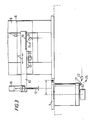
- metrological apparatus comprises a bench 2 provided with a turntable 4 for supporting a workpiece (not shown).
- a carriage 6 is supported for vertical movement on a column 8 and carries a horizontally movable arm 10.
- a stylus 12 for engaging the surface of the workpiece is comprised in a linear transducer 14, which may be inductive or capacitative for example, which is carried on one end of an arm 16 whose other end is attached to the free end of the arm 10 for pivotal movement, in the direction shown by arrow 18, about an axis 20 which is at 45 o to the horizontal.
- the arm 16 is pivotable through 180 o about the axis 20 between the end positions shown in Figure 2 in full and chain dotted lines respectively.
- the stylus 12 In the full line position, the stylus 12 is vertical and in the broken line position the stylus 12 is horizontal.
- the arrangement is such that the tip of the stylus 12a is located in substantially the same position in a radial plane of the turntable 4 when the arm 16 is in either of the two positions shown in Figure 2.
- An electric motor 3 mounted in the arm 10 is coupled to the arm 16 through a worm and wheel transmission 5 for driving the arm 16 between its two end positions.
- the stylus 12 and transducer 14 are arranged so that the stylus 12 can be deflected relative to the transducer 14 in only one direction.
- the transducer 14 is mounted in the arm 16 for rotation about an axis 7, preferably through 270 o in 30 o steps.
- a motor 9 is mounted in the arm for effecting rotation of the transducer 14.
- the transducer 14 may be rotated either to the position in which the stylus 12 is deflectable in a horizontal plane or to a position in which the stylus 12 is deflectable in a vertical plane.
- a side surface of a workpiece may conveniently be sensed and in the latter position an upwardly facing surface may conveniently be sensed.
- Surfaces facing in other directions may be sensed by rotating the transducer 14 about axis 7 to a position in which the stylus 12 is deflectable in a plane generally normal to the surface to be sensed.
- a motor 35 is provided in the carriage 6 for driving the arm 10 in the horizontal direction indicated by arrow 11, drive being transmitted from the motor 35 to the arm 11 through a rack and pinion arrangement 13 or other suitable means such as a ball screw. Movement of the arm 10 in the direction of arrow 11 causes the transducer 14 to be moved horizontally so that the tip 12a of the stylus 12 is moved radially inwardly or outwardly relative to the axis of the turntable 4, the tip 12a remaining in the radial plane throughout this movement.
- a source 15 mounted in the carriage 6 is directed towards a linear optical grating 19 carried by the arm 11 and reflected therefrom to a phototransducer 21 which provides output signals, preferably quadrature signals, from which the position and velocity of the arm 11 can be derived.
- a further phototransducer 23 provides signals from which the position and rotational velocity of the turntable 4, which is driven by a motor 33, can be derived with the aid of a light source 25 and optical grating 27 movable with the turntable 4.
- a motor 37 carried by the carriage 6 cooperates with a rack and pinion arrangement 39 (or other suitable means such as a sprocket wheel and chain) for driving the carriage 6 vertically in the direction of arrow 41.
- a constant force spring (not shown) is provided for counterbalancing this movement.
- a further optical grating 43 mounted in the column 8 reflects light from a source 27 carried by the carriage 6 to a phototransducer 31 also carried by the carriage 6 so that the transducer 31 may provide signals, preferably quadrature signals, from which the position and speed of movement of the carriage 6 may be derived.
- a host computer 22 which is provided with a keyboard 24, disc drive 26 and printer 28, is located on the bench 2 and is used for controlling the metrological apparatus, processing the measurements obtained and outputting the required metrological data.
- the host computer may, for example, be an IBM compatible PC.
- the apparatus includes a number of microprocessors 30, 32, 34, 36, 38 and 40.
- Microprocessor 30 is used as a master controller and receives instructions from the host 22 as to the operations which are to be performed by the apparatus. Such instructions are stored by the master controller 30 which, in accordance with programs stored in memory associated with the master controller, instructs and controls the remaining microprocessors, via a slave driver processor 30a, as to the action to be taken in order to carry out the instructions supplied by the host 22.
- Each of the remaining microprocessors also has memory associated with it storing the routines necessary for the performance of the instructions received from the master controller 30.
- microprocessors 32, 34, 36 and 38 are designated as slaves.
- Slave 32 controls the speed of rotation of the turntable 4.
- Slave 34 controls radial movement of the arm 10.
- Slave 36 controls vertical movement of the carriage 6.
- Slaves 32, 34 and 36 all preferably control the speeds of the respective motors 33, 35 and 37 in accordance with the teachings of our copending Patent Applications identifed as follows: Country Application No United Kingdom 8530577 China 86107433 Denmark 5531/86 Europe 86309681.4 East Germany P/297 385/4 India 892/MAS/86 Japan Not yet known USA 940506 USSR 4028602.24
- Slave 38 receives instructions from communication network 45 and controls centring and levelling motors 38a wherein the turntable 4 is displaced horizontally and/or pivotally for centring and levelling of a workpiece prior to performing measurements.
- the arrangements for centring and levelling are preferably in accordance with the disclosure of our patent application being filed simultaneously herewith and claiming priority from British Patent Application Nos. 8605325 and 8624396 in which the inventors are Anthony Bruce Barnaby and Michael Walter Mills.
- Microprocessor 40 receives data from gauging circuit 41 which receives and digitizes the signal output by the transducer 14 and from each of three interpolators 42, 44 and 46, which respectively receive signals from photoelectric transducers 23, 21 and 31 that detect the rotary movement of the turntable 4, the radial (horizontal) movement of the arm 10 and the vertical movement of the carriage 6 respectively.
- the interpolators function to provide data representing the precise positions of the turntable 4, arm 10 and carriage 6 to a resolution to a small fraction of the pitch of the optical gratings 27, 19 and 43.
- the interpolators provide resolution of the position of the transducer 14 in the radial (horizontal) direction to about 200 nanometres and in the axial (vertical) direction to about 500 nanometres and the rotational position of the workpiece can be resolved to about 3 arc seconds.
- the invention is not restricted to any specific resolution but it is preferred that resolution in the radial and vertical directions should be better than 1 micron and the rotational resolution should be better than 100 arc seconds, preferably better than 10 arc seconds.
- the transducer 14 preferably provides an output signal which resolves the position of the tip 12a of the stylus 12 to better than 20 nanometres, preferably 12 nanometres.
- the architecture shown in Figure 5 is such that the computers are arranged in three levels.
- the host 22 represents a firt level and permits the input of instructions from an operator, the transfer of appropriate instructions to the master controller, and the reception of data from the data logger 40.
- the host 22 performs calculations on that data in order to provide the required information.
- the second level is represented by the master controller 30 which, upon receipt of instructions from the host 22, transmits, in accordance with programs stored in memory associated with the master controller 30, appropriate instructions to the various slaves, via the slave driver 30a as necessary to perform the operation instructed by the host.
- the slaves 32, 34, 36 and 38, and the data logger 40 represent the third level and carry out, in accordance with programs stored in memory associated with them respectively, the detailed functions necessary to perform the operations instructed by the master controller on the instructions of the host 22.
- the master controller is arranged so that successive instructions received from the host 22 may be stored simultaneously in different portions of the associated memory so that these instructions may be acted upon in turn by the master controller 30.
- the transducer 14 is a linear transducer.
- the signal which it outputs is representative of the degree of deflection of the stylus 12.
- transducers providing the required high degree of resolution for example resolution to better than 20 nanometres suffer from the problem that their range of operation i.e. the range of movement of the tip 12a of the stylus 12 within which a linear output signal with the required resolution is provided, is highly limited.
- transducers with a suitable resolution may have a range of no more than 0.4 mm.
- the master controller 30, upon receiving information that the signal from the gauging circuit 41 has exceeded a predetermined threshold, transmits an instruction to slave 34 to activate the motor 35 whereby the arm 11 is displaced until the signal output by the gauging circuit 14 is returned to a predetermined value, defined as a null value (which may, for example, be zero).
- a null value which may, for example, be zero.
- the master controller 30 sends an instruction to the slave 36 to activate the motor 37 when the output from the gauging circuit 14 exceeds the predetermined threshold.
- the master controller 30 is arranged so that, in appropriate circumstances, activation of the motor 33 for rotating the turntable may be effected under control of signals from the transducer 14 such that when the signal therefrom exceeds a predetermined threshold the motor 33 is actuated so that the workpiece is moved as necessary to permit the transducer 14 to follow the surface of the workpiece as it moves in the horizontal and/or vertical direction.
- the stylus 12 is caused to follow the surface of the workpiece during rotation of the workpiece on the turntable 4.
- the host computer 22 obtains the metrological information required, for example as to form or errors in form, both from the signals derived from the transducer 14 and the signals derived from the phototransducers 23, 21, 31 and the associated interpolators 42, 44 and 46.
- the speed at which the stylus traverses the workpiece surface may be varied, by varying the speed of the motors driving the turntable 4 and/or the arm 10 and/or the carriage 6, so as to enable the gathering of data in a preferred manner for example to provide constant surface bandwidth whereby the results of measuring identical surface features at different radii are also identical and dependent only on the surface speed selected.
- data be taken at points on the surface of the workpiece at fixed distances apart and accordingly, with the arrangement under description, this may be achieved regardiess of, for example, different curvatures of different portions of the surface, without varying the data collection rate by varying one or more of the speeds mentioned in order to compensate for the difference in curvatures, for example.
- the master controller 30 reads positional data from the interpolators 42, 44 and 46 and the gauging circuit 41, the speed of the appropriate motors being varied in accordance with this received data and with programs stored in memory associated with the master controller 30.
- Figure 6 illustrates a cam 50 whose profile is to be measured by taking measurements at positions spaced apart by a distance ds.
- the speed of rotation of the turntable 4 in order to enable collection of data at a constant rate will have to differ from that utilised when measuring portion 53 of the cam, where ds is at a radius r2 and subtends an angle b.
- the master controller has associated with it programs for varying the speed of rotation of the turntable 4 taking these parameters into account in order that data may be collected at a constant rate at constant incremental positions of the stylus on the surface being measured.
- the speed of rotation of the turntable may be controlled in accordance with the following equation: where V is the required constant speed of traverse of the transducer over the workpiece surface, S is the signal from the linear output transducer 14 and R is the signal derived by the interpolator 44 from the transducer 21 indicating the radial position of the transducer 14.
- FIG. 7 a preferred operation for the measurement of flatness is illustrated.
- a surface 60 of a workpiece (not shown) placed upon the turntable 4 is traversed by the stylus 12 in a spiral path 62. This is achieved by causing the arm 10 to be moved radially inwardly or outwardly accordingly to whether the measurement is started near the centre or near the periphery of the surface 60, whilst rotating the turntable 4.
- the speed of rotation of the turntable is varied, as a linear function of the distance of the stylus from the centre of rotation, in order that the linear speed of traverse of the stylus over the surface is maintained constant. Data from the stylus 12 is logged at fixed time or distance intervals. Other modes of operation are possible in which, for example, the speed of rotation is kept constant.
- cylindricity of a surface 64 is measured by causing the stylus 12 to traverse a spiral (helical) path 66. This is achieved, after centring and preventing, by rotation of the turntable 4 whilst moving the carriage 6 vertically. In this measurement, the speeds of movement are maintained constant and again data is logged at fixed time intervals, these fixed intervals again resulting in the logging of data at fixed incremental distances along the path of movement of a stylus over the surface. Measurements are taken over a number of revolutions around the surface 64 i.e. the helix or spiral has multiple turn. It may be noted that the stylus may be caused to traverse a spiral or helical path over the cylindrical surface 64 for the purpose of determining the axis of the cylinder.
- conicity of a surface 70 is measured by causing the stylus 12 to traverse a spiral path 72 having several turns. This is achieved, after centring and levelling, by rotating the turntable 4 whilst moving the carriage 6 vertically and the arm 10 radially (horizontally). The radial movement is inwards if the stylus moves from a relatively wide portion to a relatively narrow portions of the surface 70 and vice versa .
- the radial movement of the arm 10 is controlled in dependence upon the magnitude of the signal output by the transducer 14 so that the stylus 12 is maintained in continuous contact with the conical surface 70 as the measurement progresses.
- thc angular velocity of the turntable 4 can be controlled as a linear function of the radial position of the arm 10 as indicated by transducer 44 so that the linear speed at which the stylus traverses the surface 70 is maintained constant. Data is logged at constant time intervals.
- the machine may be programmed for carrying out a wide variety of measurements, such as surface roughness, roundness, straightness, flatness, squareness, taper, coaxiality, parallelism, size of regular and irregular shapes.
- the transducer position and/or the speeds of one or more of the motors are varied either in sequence or simultaneously so that the transducer follows the profile being measured and/or so that measurements may be taken at constant surface intervals measurements may be performed more rapidly and efficiently than in prior art apparatus.
Landscapes
- Physics & Mathematics (AREA)
- General Physics & Mathematics (AREA)
- Length Measuring Devices With Unspecified Measuring Means (AREA)
- A Measuring Device Byusing Mechanical Method (AREA)
Applications Claiming Priority (3)
| Application Number | Priority Date | Filing Date | Title |
|---|---|---|---|
| GB8605324 | 1986-03-04 | ||
| GB868605324A GB8605324D0 (en) | 1986-03-04 | 1986-03-04 | Metrological apparatus |
| EP87301712A EP0240151B1 (de) | 1986-03-04 | 1987-02-26 | Metrologischer Apparat |
Related Parent Applications (1)
| Application Number | Title | Priority Date | Filing Date |
|---|---|---|---|
| EP87301712.3 Division | 1987-02-26 |
Publications (3)
| Publication Number | Publication Date |
|---|---|
| EP0342770A2 true EP0342770A2 (de) | 1989-11-23 |
| EP0342770A3 EP0342770A3 (en) | 1990-03-14 |
| EP0342770B1 EP0342770B1 (de) | 1994-05-18 |
Family
ID=26109848
Family Applications (2)
| Application Number | Title | Priority Date | Filing Date |
|---|---|---|---|
| EP89201828A Expired - Lifetime EP0342770B1 (de) | 1986-03-04 | 1987-02-26 | Metrologischer Apparat |
| EP89201143A Expired - Lifetime EP0335474B2 (de) | 1986-03-04 | 1987-02-26 | Metrologische Vorrichtung |
Family Applications After (1)
| Application Number | Title | Priority Date | Filing Date |
|---|---|---|---|
| EP89201143A Expired - Lifetime EP0335474B2 (de) | 1986-03-04 | 1987-02-26 | Metrologische Vorrichtung |
Country Status (1)
| Country | Link |
|---|---|
| EP (2) | EP0342770B1 (de) |
Cited By (2)
| Publication number | Priority date | Publication date | Assignee | Title |
|---|---|---|---|---|
| WO1996007868A1 (de) * | 1994-09-10 | 1996-03-14 | Forschungszentrum Jülich GmbH | Verfahren zum scannen einer probenoberfläche, insbesondere mit rastersondenmikroskopen |
| US10132622B2 (en) | 2013-02-05 | 2018-11-20 | Renishaw Plc | Method and apparatus for measuring a part |
Families Citing this family (6)
| Publication number | Priority date | Publication date | Assignee | Title |
|---|---|---|---|---|
| DE4228904A1 (de) * | 1992-08-29 | 1994-03-03 | Heidelberger Druckmasch Ag | Verfahren zum Prüfen von Druckformen vor dem Druck |
| GB2349949B (en) | 1999-05-14 | 2003-03-05 | Taylor Hobson Ltd | Metrological instrument |
| GB2350429B (en) * | 1999-05-28 | 2003-11-12 | Taylor Hobson Ltd | A metrological instrument |
| ITTO20010640A1 (it) * | 2001-07-03 | 2003-01-03 | Newlast Automation Srl | Dispositivo e metodo per la rilevazione di forme, in particolare modelli di calzatura. |
| GB2437982B (en) | 2006-05-08 | 2011-07-27 | Taylor Hobson Ltd | Metrological apparatus |
| CN105423918A (zh) * | 2015-12-15 | 2016-03-23 | 昆明理工大学 | 一种连杆机构的结构参数辨识系统及方法 |
Family Cites Families (14)
| Publication number | Priority date | Publication date | Assignee | Title |
|---|---|---|---|---|
| US3509635A (en) * | 1966-07-21 | 1970-05-05 | New Britain Machine Co | Apparatus for measuring and inspecting articles of manufacture |
| US3741659A (en) * | 1970-06-19 | 1973-06-26 | Fellows Gear Shaper Co | Bias corrected measuring instrument |
| US3678584A (en) * | 1970-08-13 | 1972-07-25 | Gen Motors Corp | Measuring probe assembly |
| US3727119A (en) * | 1971-02-01 | 1973-04-10 | Information Dev Corp | Servo controlled automatic inspection apparatus |
| US4166323A (en) * | 1973-09-14 | 1979-09-04 | Maag Gear-Wheel & Machine Co. Ltd. | Gear tester for profile and lead testing |
| GB1477508A (en) * | 1974-08-21 | 1977-06-22 | Rank Organisation Ltd | Measuring apparatus |
| DD125296A1 (de) * | 1976-01-29 | 1977-04-13 | ||
| IT1159664B (it) * | 1978-05-09 | 1987-03-04 | Dea Spa | Attrezzo orientabile per il supporto di utensili |
| GB2037436B (en) * | 1978-10-02 | 1983-04-27 | Haltronic Systems Ltd | Swivel probe |
| GB2112140B (en) * | 1981-12-16 | 1985-08-07 | Mauser Werke Oberndorf | Coordinate measuring machine |
| JPS58169001A (ja) * | 1982-03-31 | 1983-10-05 | Mitsutoyo Mfg Co Ltd | 2方向タツチセンサ |
| AU2950984A (en) * | 1983-07-27 | 1985-06-13 | Ex-Cell-O Corporation | Computer controlled contour inspection method |
| JPS61105414A (ja) * | 1984-10-29 | 1986-05-23 | Mitsutoyo Mfg Co Ltd | 三次元測定機 |
| JPS61209309A (ja) * | 1985-03-14 | 1986-09-17 | Mitsutoyo Mfg Co Ltd | 部品検査装置 |
-
1987
- 1987-02-26 EP EP89201828A patent/EP0342770B1/de not_active Expired - Lifetime
- 1987-02-26 EP EP89201143A patent/EP0335474B2/de not_active Expired - Lifetime
Cited By (2)
| Publication number | Priority date | Publication date | Assignee | Title |
|---|---|---|---|---|
| WO1996007868A1 (de) * | 1994-09-10 | 1996-03-14 | Forschungszentrum Jülich GmbH | Verfahren zum scannen einer probenoberfläche, insbesondere mit rastersondenmikroskopen |
| US10132622B2 (en) | 2013-02-05 | 2018-11-20 | Renishaw Plc | Method and apparatus for measuring a part |
Also Published As
| Publication number | Publication date |
|---|---|
| EP0342770B1 (de) | 1994-05-18 |
| EP0335474A3 (en) | 1990-03-28 |
| EP0335474B2 (de) | 1999-09-01 |
| EP0335474B1 (de) | 1994-05-18 |
| EP0342770A3 (en) | 1990-03-14 |
| EP0335474A2 (de) | 1989-10-04 |
Similar Documents
| Publication | Publication Date | Title |
|---|---|---|
| US4807152A (en) | Metrological apparatus | |
| SU1718735A3 (ru) | Контрольно-измерительное устройство | |
| EP0744678B1 (de) | Rundheits-Messvorrichtung | |
| EP0866945B1 (de) | Oberflächenformvermessung | |
| EP2037211B1 (de) | Vorrichtung zur messung einer oberflächenform und verfahren zur messung einer oberflächenform | |
| US5184428A (en) | Device for adjusting a cnc-controlled grinder | |
| CN107883871A (zh) | 一种蜗杆测量方法 | |
| JP6316858B2 (ja) | モータの軸精度自動測定装置 | |
| JP2016065751A (ja) | 真円度測定機およびその制御方法 | |
| JPH10505009A (ja) | 精密穿孔の際の継ぎ合わせ誤差及び磨損誤差の検知及び補正のための方法及び装置 | |
| US5035554A (en) | Method for determining the radius described by a tool | |
| EP0335474B2 (de) | Metrologische Vorrichtung | |
| US4606130A (en) | Apparatus for monitoring the diameters and axial positions of workpieces in machine tools | |
| JP2001141444A (ja) | V溝形状測定方法及び装置 | |
| US4646566A (en) | Apparatus for testing gear wheel tooth flank profile and tooth flank lines (toot angle) and a method for positioning this apparatus for the measurement apparatus | |
| EP0381777B1 (de) | Reifenrillenvorrichtung und verfahren | |
| JP2001264048A (ja) | V溝形状測定方法及び装置 | |
| JP3748866B2 (ja) | 工具測定装置および方法 | |
| CN1004514B (zh) | 就地测量大齿轮齿形的方法与装置 | |
| GB2154163A (en) | Cylindrical grinding machine having position detection probe | |
| JP3452618B2 (ja) | レンズ芯取機およびレンズ芯取り方法 | |
| JP2624248B2 (ja) | 計測研磨装置 | |
| GB2307988A (en) | Surface form measurement | |
| JP3085352B2 (ja) | 真円度測定機の測定対象自動認識方法及びその装置 | |
| CN216097875U (zh) | 壳体圆跳自动检测系统 |
Legal Events
| Date | Code | Title | Description |
|---|---|---|---|
| PUAI | Public reference made under article 153(3) epc to a published international application that has entered the european phase |
Free format text: ORIGINAL CODE: 0009012 |
|
| AC | Divisional application: reference to earlier application |
Ref document number: 240151 Country of ref document: EP |
|
| AK | Designated contracting states |
Kind code of ref document: A2 Designated state(s): CH DE GB IT LI SE |
|
| PUAL | Search report despatched |
Free format text: ORIGINAL CODE: 0009013 |
|
| RHK1 | Main classification (correction) |
Ipc: G01B 7/00 |
|
| AK | Designated contracting states |
Kind code of ref document: A3 Designated state(s): CH DE GB IT LI SE |
|
| 17P | Request for examination filed |
Effective date: 19900903 |
|
| 17Q | First examination report despatched |
Effective date: 19910611 |
|
| GRAA | (expected) grant |
Free format text: ORIGINAL CODE: 0009210 |
|
| AC | Divisional application: reference to earlier application |
Ref document number: 240151 Country of ref document: EP |
|
| AK | Designated contracting states |
Kind code of ref document: B1 Designated state(s): CH DE GB IT LI SE |
|
| REF | Corresponds to: |
Ref document number: 3789875 Country of ref document: DE Date of ref document: 19940623 |
|
| ITF | It: translation for a ep patent filed | ||
| EAL | Se: european patent in force in sweden |
Ref document number: 89201828.4 |
|
| PLBI | Opposition filed |
Free format text: ORIGINAL CODE: 0009260 |
|
| 26 | Opposition filed |
Opponent name: FAG KUGELFISCHER GEORG SCHAEFER AKTIENGESELLSCHAFT Effective date: 19950215 Opponent name: REMOG PRAEZISIONSMESSTECHNIK GMBH Effective date: 19950215 |
|
| RDAH | Patent revoked |
Free format text: ORIGINAL CODE: EPIDOS REVO |
|
| APAC | Appeal dossier modified |
Free format text: ORIGINAL CODE: EPIDOS NOAPO |
|
| APAE | Appeal reference modified |
Free format text: ORIGINAL CODE: EPIDOS REFNO |
|
| REG | Reference to a national code |
Ref country code: GB Ref legal event code: 732E |
|
| REG | Reference to a national code |
Ref country code: CH Ref legal event code: PUE Owner name: RANK TAYLOR HOBSON LIMITED TRANSFER- TAYLOR HOBSON |
|
| APCC | Communication from the board of appeal sent |
Free format text: ORIGINAL CODE: EPIDOS OBAPO |
|
| APCC | Communication from the board of appeal sent |
Free format text: ORIGINAL CODE: EPIDOS OBAPO |
|
| APCC | Communication from the board of appeal sent |
Free format text: ORIGINAL CODE: EPIDOS OBAPO |
|
| PGFP | Annual fee paid to national office [announced via postgrant information from national office to epo] |
Ref country code: SE Payment date: 19990204 Year of fee payment: 13 |
|
| PGFP | Annual fee paid to national office [announced via postgrant information from national office to epo] |
Ref country code: CH Payment date: 19990211 Year of fee payment: 13 |
|
| APAC | Appeal dossier modified |
Free format text: ORIGINAL CODE: EPIDOS NOAPO |
|
| PLBO | Opposition rejected |
Free format text: ORIGINAL CODE: EPIDOS REJO |
|
| PLBN | Opposition rejected |
Free format text: ORIGINAL CODE: 0009273 |
|
| STAA | Information on the status of an ep patent application or granted ep patent |
Free format text: STATUS: OPPOSITION REJECTED |
|
| 27O | Opposition rejected |
Effective date: 19990405 |
|
| PG25 | Lapsed in a contracting state [announced via postgrant information from national office to epo] |
Ref country code: SE Free format text: LAPSE BECAUSE OF NON-PAYMENT OF DUE FEES Effective date: 20000227 |
|
| PG25 | Lapsed in a contracting state [announced via postgrant information from national office to epo] |
Ref country code: LI Free format text: LAPSE BECAUSE OF NON-PAYMENT OF DUE FEES Effective date: 20000229 Ref country code: CH Free format text: LAPSE BECAUSE OF NON-PAYMENT OF DUE FEES Effective date: 20000229 |
|
| EUG | Se: european patent has lapsed |
Ref document number: 89201828.4 |
|
| REG | Reference to a national code |
Ref country code: CH Ref legal event code: PL |
|
| PGFP | Annual fee paid to national office [announced via postgrant information from national office to epo] |
Ref country code: GB Payment date: 20010212 Year of fee payment: 15 |
|
| PGFP | Annual fee paid to national office [announced via postgrant information from national office to epo] |
Ref country code: DE Payment date: 20010425 Year of fee payment: 15 |
|
| REG | Reference to a national code |
Ref country code: GB Ref legal event code: IF02 |
|
| PG25 | Lapsed in a contracting state [announced via postgrant information from national office to epo] |
Ref country code: GB Free format text: LAPSE BECAUSE OF NON-PAYMENT OF DUE FEES Effective date: 20020226 |
|
| PG25 | Lapsed in a contracting state [announced via postgrant information from national office to epo] |
Ref country code: DE Free format text: LAPSE BECAUSE OF NON-PAYMENT OF DUE FEES Effective date: 20020903 |
|
| GBPC | Gb: european patent ceased through non-payment of renewal fee |
Effective date: 20020226 |
|
| PG25 | Lapsed in a contracting state [announced via postgrant information from national office to epo] |
Ref country code: IT Free format text: LAPSE BECAUSE OF NON-PAYMENT OF DUE FEES;WARNING: LAPSES OF ITALIAN PATENTS WITH EFFECTIVE DATE BEFORE 2007 MAY HAVE OCCURRED AT ANY TIME BEFORE 2007. THE CORRECT EFFECTIVE DATE MAY BE DIFFERENT FROM THE ONE RECORDED. Effective date: 20050226 |
|
| APAH | Appeal reference modified |
Free format text: ORIGINAL CODE: EPIDOSCREFNO |