EP0342546A2 - Enthaarungsvorrichtung - Google Patents
Enthaarungsvorrichtung Download PDFInfo
- Publication number
- EP0342546A2 EP0342546A2 EP89108602A EP89108602A EP0342546A2 EP 0342546 A2 EP0342546 A2 EP 0342546A2 EP 89108602 A EP89108602 A EP 89108602A EP 89108602 A EP89108602 A EP 89108602A EP 0342546 A2 EP0342546 A2 EP 0342546A2
- Authority
- EP
- European Patent Office
- Prior art keywords
- hair
- engagement
- electrically powered
- depilatory device
- rollers
- Prior art date
- Legal status (The legal status is an assumption and is not a legal conclusion. Google has not performed a legal analysis and makes no representation as to the accuracy of the status listed.)
- Withdrawn
Links
Images


Classifications
-
- A—HUMAN NECESSITIES
- A45—HAND OR TRAVELLING ARTICLES
- A45D—HAIRDRESSING OR SHAVING EQUIPMENT; EQUIPMENT FOR COSMETICS OR COSMETIC TREATMENTS, e.g. FOR MANICURING OR PEDICURING
- A45D26/00—Hair-singeing apparatus; Apparatus for removing superfluous hair, e.g. tweezers
- A45D26/0023—Hair-singeing apparatus; Apparatus for removing superfluous hair, e.g. tweezers with rotating clamping elements
- A45D26/0033—Hair-singeing apparatus; Apparatus for removing superfluous hair, e.g. tweezers with rotating clamping elements with rollers
- A45D26/0038—Hair-singeing apparatus; Apparatus for removing superfluous hair, e.g. tweezers with rotating clamping elements with rollers power-driven
-
- A—HUMAN NECESSITIES
- A45—HAND OR TRAVELLING ARTICLES
- A45D—HAIRDRESSING OR SHAVING EQUIPMENT; EQUIPMENT FOR COSMETICS OR COSMETIC TREATMENTS, e.g. FOR MANICURING OR PEDICURING
- A45D26/00—Hair-singeing apparatus; Apparatus for removing superfluous hair, e.g. tweezers
- A45D26/0042—Hair-singeing apparatus; Apparatus for removing superfluous hair, e.g. tweezers with flexible members provided with slits opening and closing during use
Definitions
- the present invention relates to depilatory devices and techniques generally and more particularly to powered mechanical depilatory devices.
- an electrically powered depilatory device including a hand held portable housing, motor apparatus disposed in the housing, and a helical spring comprising a plurality of adjacent windings arranged to be driven by the motor apparatus in rotational sliding motion relative to the skin bearing hair to be removed, the helical spring including an arcuate hair engaging portion arranged to define a convex side whereat the windings are spread apart and a concave side corresponding thereto whereat the windings are pressed together, the rotational motion of the helical spring producing continuous motion of the windings from a spread apart orientation at the convex side to a pressed together orientation at the concave side for engagement and plucking of hair from the skin, whereby the surface velocities of the windings relative to the hair greatly exceeds the surface velocity of the housing relative thereto.
- the present invention seeks to provide a mechanical depilatory device which differs from the prior art devices described above and which provides efficient and relatively painless hair removal.
- an electrically powered depilatory device including a hand held portable housing, first and second hair engagement elements defining respective first and second hair engagement surfaces having different surface hardnesses, motor apparatus for driving at least one of the first and second hair engagement elements in relative motion, whereby hair is engaged between the first and second hair engagement surfaces and thus removed.
- the difference in surface hardness of the first and second hair engagement elements is such that upon engagement of hair therebetween a recess or depression is defined in the less hard of the two surfaces, at least partially accommodating the engaged hair.
- the first hair engagement surface may be defined by an endless belt or band, which may be smooth, conditioned, or configured as appropriate.
- the belt may be formed with gear teeth.
- the belt may be flat or curved and may have any suitable cross sectional configuration. It will be appreciated that the terms "belt” and "band” are used in an extremely broad sense to include any type of endless element which can perform depilation as described herein.
- the second hair engagement surface may be defined by one or more rollers which engage the endless belt or band.
- the rollers may be of any suitable configuration and, for example, may be straight or curved, smooth or conditioned as appropriate.
- the rollers may be formed with gear teeth, and may be formed with recesses, slits or any other suitable structural features.
- the first hair engagement element may comprise one or more rollers and the second hair engagement element may comprise a rotating disk in frictional driving engagement with the roller or rollers.
- the roller or rollers may be smooth or grooved. Where a plurality of rollers is employed, they may be arranged in a plane or otherwise.
- the first hair engagement element may alternatively comprise an apertured disk.
- the second hair engagement element may comprise a plurality of rings instead of a disk and may be smooth or grooved.
- first and second hair engagement elements may be arranged such that the relative engagement thereof produces closing of gaps defined in one or both of the engagement elements.
- the relative motion between the first and second hair engagement elements may be rotary, linear or otherwise.
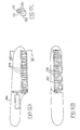
- FIGs. 1A and 1B illustrate a depilatory device constructed and operative in accordance with a preferred embodiment of the present invention and comprising a housing 10 including a handle portion 12 and an operating head portion 14.
- Rotatably mounted within the operating head portion 14 of the housing 10 is a rotating member 16.
- Member 16 includes a collar portion 18, which is slidably and rotatably mounted on a shaft 20, which is fixedly mounted onto a wall 22 of housing operating head portion 14.
- Rotating member 16 includes a top surface 24 onto which are formed gear teeth for operative engagement with a gear 26 which is driven by the output shaft 28 of an electric motor 30.
- Rotating member 16 also includes a bottom surface which defines a recess 32 into which is fixedly seated an annulus 34 formed of rubber or other material having a high coefficient of friction. Annulus 34 rotates together with member 16 about an axis 40 defined by shaft 20.
- a plurality of rollers 42 are rotatably mounted for rotation driven by frictional engagement with annulus 34. Rollers 42 are typically rotatably retained between a peripheral rim 44 preferably formed as part of housing operating head portion 14 and a center retaining plate 46, which may be removably mounted onto shaft 20, as by a screw 48. A plurality of connecting elements 50 may be fixed to retaining plate 46 and extend generally radially outward into engagement with rim 44.
- a compression spring 52 is seated at one end onto wall 22 and at its opposite end onto member 16. At each end a pressure bearing 56, comprising a plurality of balls and a washer, is provided in order to enable spring 52 to remain static notwithstanding rotation of element 16. Spring 52 is operative to urge member 16 and annulus 34 into driving frictional engagement with rollers 42.
- the device of Figs. 1A and 1B operates generally as follows.
- the rotational motion of annulus 34 in frictional engagement with rollers 42 causes rotation of rollers 42 and tends to draw individual hairs into frictional engagement between the annulus 34 and the rollers 42.
- the annulus 34 rotates at a rotational speed of about 800 rpm
- rollers 42 rotate at a rotational speed of about 7000 rpm and at generally the same linear speed as that of the annulus 34.
- FIGs. 2A and 2B illustrate an alternative embodiment of the present invention which is generally identical to that shown in Figs. 1A and 1B, with the following exception.
- a static operating head cover 60 having spaced apertures 62.
- identical reference numerals are employed in Figs. 1A and 2A to indicate identical components.
- annulus 34 when the operating head is located in propinquity to hair bearing skin, the rotational motion of annulus 34 tends to draw individual hairs extending through apertures 62 into frictional engagement between the annulus 34 and the cover 60. Continued rotational motion of the annulus 34 and the cover 60 tends to quickly pull the hair out of the skin.
- the annulus 34 rotates at a rotational speed of about 800 rpm relative to the cover 60.
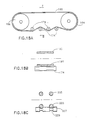
- Figs. 3A - 3C illustrate three alternative roller configurations for the embodiment of Figs. 1A and 1B.
- Fig. 3A illustrates the provision of smooth surfaced rollers, which may be formed of any suitable material, such as metal, plastic or rubber.
- Fig. 3B illustrates the provision of rollers having longitudinal grooves to enhance the frictional engagement of the rollers with the annulus 34 (Fig. 1A) and the hair, while Fig. 3C illustrates the use of rollers having a roughened surface to enhance the frictional engagement thereof with the annulus 34 and the hair.
- FIGs. 4A and 4B illustrate an alternative embodiment of the invention, identical to that illustrated in Figs. 1A and 1B, with the following exception.
- the annulus 34 and the rollers 42 lie in respective parallel planes, here, both the annulus 34 and the rollers 42 are arranged to lie over a truncated generally conical surface.
- a possible advantage of this arrangement is enhanced ease of engagement with certain regions of the body.
- identical reference numerals are employed as in Figs. 1A and 1B for the various elements of the apparatus, notwithstanding the different geometrical orientation of some of the elements.
- Figs. 5A and 5B illustrate a further alternative embodiment of the present invention which is generally identical to that of Figs. 1A and 1B with the following exceptions.
- the bottom surface, preferably, of annulus 34 is formed with a multiplicity of generally circumferentially extending slits 70.
- Curved rollers 72 are employed for frictional engagement with the annulus 34 and for simultaneously forcing the slits together, as illustrated.
- Curved rollers 72 are typically formed with varying cross-sectional radii, preferably such that the cross-sectional radii are longest at the ends of the roller and are shortest at the midpoint of the roller.
- Figs. 5A and 5B provides enhanced hair engagement inasmuch as it permits hair to enter slits 70 when the slits are spread, i.e. between engagements with rollers 72.
- the slit is squeezed closed, trapping engaged hairs therewithin and generally causing them to be pulled out of the skin.
- Figs. 6A and 6B illustrate a further alternative embodiment of the invention which is essentially similar to that of Figs. 5A and 5B but employs straight rollers 42 (i.e., rollers of generally uniform cross-section) disposed along a generally truncated, preferably conical surface, as illustrated in Fig. 4A.
- the annulus 34 remains essentially planar, such that the pressure engagement of angularly disposed straight rollers 42 with the annulus 34 bearing slits 70 produces squeezing together of the slits 70.
- FIG. 7 illustrates an alternative operating head configuration useful in the embodiment of Figs. 1A and 1B.
- the embodiment of Fig. 7 is identical to that employed in the apparatus of Figs. 1A and 1B except that the annulus 34 of Fig. 1A is replaced by a ring 80 having a generally circular, ovular, elliptical or otherwise curved cross-section, the remainder of the structure remaining generally the same.
- FIG. 8A illustrates two alternative embodiments of a static operating head cover useful in the embodiment of Figs. 2A and 2B.
- Fig. 8A illustrates an operating head cover 86 defining a curved inner surface 88 which is particularly suitable for engagement with an annulus 34 of the type shown in Fig. 5A having slits 70, for squeezing the slits together.
- Fig. 8B illustrates a static operating head cover 90 defining an inner surface 92 having a truncated generally conical configuration, as in the analogous roller embodiment of Fig. 6A.
- This embodiment is similarly particularly suitable for engagement with an annulus 34 of the type illustrated in Fig. 6A having slits 70, for squeezing the slits together.
- Figs. 9A and 9B illustrate an alternative embodiment of a depilatory device comprising a housing 100 in which are rotatably disposed first and second rollers 102 and 104, arranged for mutual frictional engagement.
- Rollers 102 and 104 are preferably formed of respective resilient materials, typically of two different materials of different harnesses.
- a motor 106 disposed in housing 100, is arranged to drive roller 102 in rotary motion via a gear 108 which is affixed to an end of roller 102 and is engaged by a corresponding gear 110, affixed to the output shaft 112 of the motor 106.
- Rotational motion of roller 102 produces corresponding rotational motion of roller 104 in an opposite direction, due to the frictional engagement between the two rollers.
- the relative motion of the two rollers may engage hair therebetween and pull the hair into the recess or deformation produced in one or each of the rollers when they are pressed against one another.
- Figs. 10A and 10B illustrate an alternative embodiment of the depilatory device of Figs. 9A and 9B wherein the difference lies in the fact that the two rollers are coupled by gearing, there being provided an additional gear 114, which engages gear 108 and is affixed to the end of roller 104. Otherwise, the structure and operation of the two embodiments is the same.
- roller 102 is formed of a relatively soft resilient material, such as rubber, having multiple circumferential slits 120 spaced along its length
- roller 104 is formed of a relatively hard material such as plastic, and comprises a series of curved elongate sections 122 (i.e.
- roller 102 is formed of a relatively resilient material, such as rubber, and has multiple circumferential slits 120 at intervals along its length, but here roller 104 is replaced by a static engagement member 124 which engages roller 102 and is operative to press the slits 120 together for grasping hair which has entered the slits, thereby causing fixed entrapment of the hair therewith and enhanced pulling thereby of the hair from the skin.
- FIG. 13A and 13B illustrate a further alternative embodiment of the invention.
- an endless band or belt 160 typically formed of a resilient material such as rubber, is disposed within a housing 162 on support rollers 164.
- a motor 166 also disposed interiorly of housing 162, drives one of the support rollers 164 via a gear 168 which is affixed to the drive shaft 170 of the motor 166.
- a platen element 172 which may be generally planar as shown or alternatively may comprise a plurality of rollers, is disposed interiorly of the band 160.
- a plurality of rollers 174 are operative to maintain a pressure engagement of the band 160 against platen element 172, such that linear motion of the band 160 produces corresponding rotation of rollers 174. Hair may be engaged between the various rollers and the bands for producing hair removal.
- Figs. 14A and 14B illustrate an alternative embodiment of the apparatus of Figs. 13A and 13B, the difference being in the structure of the band and the rollers.
- the outer surface of band 160 is provided with elongate slits 180.
- the rollers 182 are configured to be curved (i.e. with varying cross-sectional radii, preferably such that the cross-sectional radii are longest at the ends of the roller and are shortest at the midpoint of the roller) such that engagement between the rollers 182 and the band 160 serves to squeeze the slits together, thus trapping hair which may have entered gaps defined by the slits.
- a motor 190 disposed in a housing 191, produces reciprocating linear motion of a platen element 192 via a crankshaft drive 194.
- Platen element 192 is supported for linear motion by support rollers 196 and defines a preferably resilient bottom surface 198, typically formed of rubber.
- a plurality of rollers 200 are disposed, typically in a mutually parallel orientation, in pressure engagement with the bottom surface 198, thereby defining engagement locations between each of rollers 200 and bottom surface 198. Recesses may be formed at these locations if rollers 200 are harder than surface 198.
- Figs. 16A - l6E illustrate five alternative configurations of bottom surface 198 and of rollers 200.
- the bottom surface 198 is generally uniform and generally planar and the rollers 200 are straight (i.e. of generally uniform cross section).
- the bottom surface 198 comprises a plurality of spaced strips 202, preferably having generally rectangular cross-sections, and the rollers 200 are of generally uniform cross section.
- the bottom surface 198 is formed with a plurality of elongate slits 204 and the rollers 206 are curved (i.e. with varying cross-sectional radii preferably such that the cross-sectional radii are longest at the ends of the roller and are shortest at the midpoint of the roller), analogous to the embodiment of Fig. 14B.
- the bottom surface 198 comprises a plurality of strips 208 having generally circular, ovular or elliptical cross sections and the rollers 200 are straight.
- rollers 200 may be smooth, grooved or otherwise conditioned.
- Fig. 16E illustrates an alternative embodiment of the invention, similar to that illustrated in Fig. 16D.
- the cylindrical rollers 200 are replaced by rollers 207 having formed therein annular recesses 209 at locations corresponding to strips 208.
- Recesses 209 typically have generally curved configurations, which need not be of the same shape as the cross-sections of strips 208.
- FIG. 17A illustrates a construction, such as that shown in Figs. 9A, 9B, 9C and 9D, wherein two rollers 230 and 232 are employed for engaging hair.
- roller 230 is relatively soft and roller 232 is relatively hard, such that frictional engagement therebetween produces a recess or deformation 234 in roller 230, as shown.
- a recess 234 provides enhanced hair engagement due to the relatively large dimensions of the surface over which the hair is pressed between the two rollers. This arrangement also avoids localized pressure between the rollers on the hair which could cause breakage of the hair, thereby precluding effective uprooting thereof from the skin.
- Fig. 17A illustrates a situation wherein the hair 236 extends generally straight through and past the rollers
- Fig. 17B illustrates a situation wherein the hair 236 becomes wound around one of the rollers. It is immaterial which of the two situations occurs in practice. Normally, some of the hairs tend to pass straight through as in Fig. 17A and some tend to become wound as in Fig. 17B.
- Fig. 17E illustrates a situation wherein both of the rollers are of similar hardness.
- deformations are formed in both of the rollers 230 and 232, the deformations defining a generally planar interface 234 at the mutual boundary of the rollers, whose cross sections are otherwise generally circular.
- the deformations are defined by the amount of deviation from the circular configuration, of the cross sections of the rollers.
- Fig. 17C illustrates the hair engagement characteristic of the embodiments of Figs. 1A, 1B, 4A, 4B, 5A, 5B, 6A, 6B, 13A, 13B, 14A, 14B, 15A, 15B, 16A - 16E and 18A - 18C.
- a recess or deformation 240 is defined in a relatively soft annulus 242 by pressure engagement with a relatively harder roller 244.
- the hair 246 passes between the roller and the annulus and is engaged within recess 240, the engagement being enhanced by the relatively large surface area defined by the recess.
- the terms "recess" and “deformation” are and have been used interchangeably in a broad sense.
- Fig. 17D illustrates the hair engagement characteristic of the embodiment of Figs. 2A and 2B.
- a recess 250 is defined in a relatively soft annulus 252 by pressure engagement with a relatively harder cover 254.
- the hair 256 passes between the cover and the annulus and is engaged in recess 250, the engagement being enhanced by the relatively large surface areas thus defined by the recess.
- Figs. 18A and 18B illustrate an alternative embodiment of the structure of Figs. 13A, 13B, 14A and 14B.
- the platen member 172 is eliminated and rollers 174 are located on both sides of the endless band or belt 160.
- adjacent rollers are located on opposite sides of band 160.
- Fig. 18C illustrates an alternative embodiment of the invention, similar to that illustrated in Fig. 16E, wherein the single endless band or belt 160 is replaced by a plurality of endless bands, belts or rings 205, arranged in a generally mutual parallel orientation and typically of generally circular cross section.
- rollers 207 have formed therein annular recesses 209 at locations corresponding to rings 205.
- Recesses 209 typically have generally curved configurations, which need not be of the same shape as the cross-sections of bands 205.
- Fig. 19A illustrates apparatus generally similar to that of Fig. 18A wherein the endless belt 160 is formed with gear teeth 220, preferably located on its outer surface.
- the belt 160 is driven by gear engagement with a driving roller 222 which is formed with gear teeth 224 engaging gear teeth 220.
- Fig. 19B illustrates a somewhat different configuration of the embodiment of Fig. 19A in that only one support roller 164 is provided.
- Fig. 19C illustrates a further alternative embodiment of the invention wherein a pair of belts 230 and 232 preferably having interdigitated gear teeth 233 are arranged to be driven in synchronization by at least one of rollers 234, 236, 238 and 240.
Landscapes
- Massaging Devices (AREA)
- Dry Shavers And Clippers (AREA)
- Brushes (AREA)
Applications Claiming Priority (2)
| Application Number | Priority Date | Filing Date | Title |
|---|---|---|---|
| IL86447 | 1988-05-19 | ||
| IL8644788A IL86447A (en) | 1988-05-19 | 1988-05-19 | Electrically powered depilatory device |
Publications (2)
| Publication Number | Publication Date |
|---|---|
| EP0342546A2 true EP0342546A2 (de) | 1989-11-23 |
| EP0342546A3 EP0342546A3 (de) | 1991-01-23 |
Family
ID=11058849
Family Applications (1)
| Application Number | Title | Priority Date | Filing Date |
|---|---|---|---|
| EP19890108602 Withdrawn EP0342546A3 (de) | 1988-05-19 | 1989-05-12 | Enthaarungsvorrichtung |
Country Status (13)
| Country | Link |
|---|---|
| US (1) | US5078715A (de) |
| EP (1) | EP0342546A3 (de) |
| JP (1) | JPH0260603A (de) |
| AU (1) | AU3512489A (de) |
| BR (1) | BR8902203A (de) |
| ES (1) | ES2014356A6 (de) |
| FR (1) | FR2631528A1 (de) |
| GR (1) | GR890100323A (de) |
| IL (1) | IL86447A (de) |
| IT (1) | IT1229354B (de) |
| NZ (1) | NZ229170A (de) |
| PT (1) | PT90577A (de) |
| ZA (1) | ZA893222B (de) |
Cited By (7)
| Publication number | Priority date | Publication date | Assignee | Title |
|---|---|---|---|---|
| FR2658050A1 (fr) * | 1990-02-14 | 1991-08-16 | Moulinex Sa | Appareil epilatoire. |
| WO1993009694A1 (de) * | 1991-11-20 | 1993-05-27 | Payer Elektroprodukte Gesellschaft M.B.H. | Enthaarungsgerät |
| US5377699A (en) * | 1993-04-02 | 1995-01-03 | Varnum; Shirley | Hair abrader |
| EP0622033A3 (de) * | 1993-04-15 | 1995-03-15 | Matsushita Electric Works Ltd | Enthaarungsvorrichtung. |
| DE102004047875A1 (de) * | 2004-10-01 | 2006-04-20 | Braun Gmbh | Klemmeinrichtung für ein Epilationsgerät |
| US20140114328A1 (en) * | 2012-10-12 | 2014-04-24 | Braun Gmbh | Epilator |
| US9435003B2 (en) | 2010-10-05 | 2016-09-06 | Lifecell Corporation | Machine and method for hair or bristle removal |
Families Citing this family (10)
| Publication number | Priority date | Publication date | Assignee | Title |
|---|---|---|---|---|
| JPH0489207U (de) * | 1990-12-10 | 1992-08-04 | ||
| US5234441A (en) * | 1992-01-06 | 1993-08-10 | Braun Aktiengesellschaft | Epilating appliance |
| US5196021A (en) * | 1992-02-25 | 1993-03-23 | Perfect Lady Ltd. | Depilatory device |
| EP0760219B1 (de) * | 1995-08-28 | 2001-10-10 | Matsushita Electric Works, Ltd. | Handenthaarungsvorrichtung |
| EP0921744B1 (de) * | 1996-08-06 | 2002-06-12 | Braun GmbH | Drehzylinder für ein epilationsgerät |
| TW443921B (en) * | 1998-04-15 | 2001-07-01 | Matsushita Electric Works Ltd | Depilator |
| FR2810216B1 (fr) | 2000-06-15 | 2002-08-16 | Seb Sa | Appareil a epiler a pinces portees par une chaine |
| GB2389256B (en) * | 2002-05-31 | 2005-12-21 | Hitachi Ltd | Semiconductor integrated circuit device for communication radio-communications apparatus and transmission starting method |
| US20040167481A1 (en) * | 2003-01-16 | 2004-08-26 | Conair Corporation | Hand-held buffing device |
| EP2106718B1 (de) * | 2005-04-18 | 2010-11-17 | Koninklijke Philips Electronics N.V. | Enthaarungsgerät |
Family Cites Families (45)
| Publication number | Priority date | Publication date | Assignee | Title |
|---|---|---|---|---|
| US1232617A (en) * | 1916-01-25 | 1917-07-10 | John L Shipp | Spring hair-remover. |
| GB203970A (en) * | 1922-12-13 | 1923-09-20 | Charles Davis | Improvements in depilatory apparatus |
| GB225445A (en) * | 1924-03-27 | 1924-12-04 | Chin Leong Li | Improvements in and relating to hair removing instruments |
| US1875980A (en) * | 1927-11-23 | 1932-09-06 | Ringham George Cowley | Machine for plucking birds |
| US1743590A (en) * | 1928-11-14 | 1930-01-14 | Binz Matilde | Hair puller |
| FR667265A (fr) * | 1929-01-11 | 1929-10-15 | Appareil à plumer les volailles | |
| US1923415A (en) * | 1930-12-11 | 1933-08-22 | Bingham George Cowley | Machine for plucking and stubbing birds |
| FR737028A (fr) * | 1932-05-11 | 1932-12-06 | Machine à plumer les volailles | |
| CH179261A (fr) * | 1934-11-07 | 1935-08-31 | Macioce Michel | Appareil dépilatoire. |
| US2083380A (en) * | 1935-01-07 | 1937-06-08 | Wm Meyer Company | Device for shaping eyebrows and the like |
| FR788130A (fr) * | 1935-04-02 | 1935-10-04 | Commande automatique et alternative des pinces des tourteaux rotatifs | |
| US2112230A (en) * | 1935-10-21 | 1938-03-29 | James M Stockett | Feather plucking machine |
| US2458911A (en) * | 1944-08-29 | 1949-01-11 | Kerr Ellen | Device for depilatory purposes |
| US2592484A (en) * | 1946-06-15 | 1952-04-08 | Moreton A Smith | Power-driven tweezer |
| US2496223A (en) * | 1946-07-13 | 1950-01-31 | Joseph C Lanzisera | Poultry plucker |
| US2423245A (en) * | 1946-11-09 | 1947-07-01 | Carl E Magnus | Method of and device for extracting hairs by using adhesive tape |
| US2486616A (en) * | 1947-11-22 | 1949-11-01 | Carl J Schubiger | Hair tweezer |
| CH268696A (de) * | 1948-09-02 | 1950-05-31 | Fischer Rudolf | Haarentfernungsapparat. |
| FR1017490A (fr) * | 1950-01-27 | 1952-12-11 | Machine à plumer la volaille | |
| US2638623A (en) * | 1950-03-07 | 1953-05-19 | Ajax Pickers Inc | Dry picker for poultry |
| GB788072A (en) * | 1955-04-13 | 1957-12-23 | Anthony George Budd | Improvements in or relating to apparatus for carrying out plucking, stubbing and like operations |
| FR1123971A (fr) * | 1955-05-11 | 1956-10-02 | Perfectionnements aux machines à plumer les volailles | |
| FR1151495A (fr) * | 1956-03-05 | 1958-01-30 | Machine à plumer la volaille | |
| US2900661A (en) * | 1957-03-11 | 1959-08-25 | Schnell Carl | Plucking device for feathers, hairs or the like |
| US3150409A (en) * | 1963-04-10 | 1964-09-29 | Frederick F Wilcox | Dehairing and skinning device |
| US3613690A (en) * | 1969-07-25 | 1971-10-19 | Francis Lee Newell | Hair removal tool |
| FR2126084A1 (de) * | 1971-02-24 | 1972-10-06 | Warde Jacques | |
| US3911530A (en) * | 1973-02-05 | 1975-10-14 | James S Kalfsbeek | System and method for removing feathers from ducks and other fowl |
| FR2245314A1 (en) * | 1973-10-02 | 1975-04-25 | Amstutz Daniel | Mechanical device for depilation of superfluous hair - has two rotating bands which frictionally grip and pull out hairs |
| FR2307491A1 (fr) * | 1975-04-15 | 1976-11-12 | Dzikowski Francis | Appareil a epiler automatique |
| GB1508528A (en) * | 1975-12-09 | 1978-04-26 | Daar Y | Apparatus for plucking hair from skin |
| US4171701A (en) * | 1977-07-01 | 1979-10-23 | Clairol Incorporated | Tweezer |
| NL7805230A (nl) * | 1978-05-16 | 1979-11-20 | Philips Nv | Epileerapparaat. |
| FR2454283A1 (fr) * | 1979-04-18 | 1980-11-14 | Lamy Perret Emile | Appareil a epiler les duvets |
| IE54383B1 (en) * | 1982-08-20 | 1989-09-13 | Improver Corp | Apparatus for hair removal |
| CH652899A5 (en) * | 1983-04-11 | 1985-12-13 | Reine Damiani | Hair-removing apparatus |
| FR2556939B1 (fr) * | 1983-12-22 | 1987-10-23 | Jean Alazet | Appareil a epiler |
| FR2588732B1 (fr) * | 1985-10-23 | 1991-02-08 | Alazet Jean | Appareil a epiler |
| FR2598067A1 (fr) * | 1986-05-02 | 1987-11-06 | Guillon Robert | Appareil pour pratiquer l'epilation |
| EP0270222A1 (de) * | 1986-10-10 | 1988-06-08 | Jal Hammoudi Jabouri | Haarentfernungsmechanismus |
| IL81780A (en) * | 1987-03-04 | 1988-09-30 | Hair Remover Ltd | Depilatory device for removing hair |
| IL81779A0 (en) * | 1987-03-04 | 1987-10-20 | Gross Joseph | Depilatory device |
| IL82002A0 (en) * | 1987-03-25 | 1987-10-20 | Gen Ideas & Prod Ltd | Depilatory device |
| US4960421A (en) * | 1988-02-22 | 1990-10-02 | Yair Daar | Depilatory device |
| US4917678A (en) * | 1988-09-01 | 1990-04-17 | Remington Products, Inc. | Depilatory device |
-
1988
- 1988-05-19 IL IL8644788A patent/IL86447A/en unknown
-
1989
- 1989-05-02 ZA ZA893222A patent/ZA893222B/xx unknown
- 1989-05-05 US US07/347,917 patent/US5078715A/en not_active Expired - Fee Related
- 1989-05-05 IT IT8920400A patent/IT1229354B/it active
- 1989-05-11 BR BR898902203A patent/BR8902203A/pt unknown
- 1989-05-12 EP EP19890108602 patent/EP0342546A3/de not_active Withdrawn
- 1989-05-15 GR GR890100323A patent/GR890100323A/el unknown
- 1989-05-16 FR FR8906340A patent/FR2631528A1/fr not_active Withdrawn
- 1989-05-17 PT PT90577A patent/PT90577A/pt not_active Application Discontinuation
- 1989-05-17 NZ NZ229170A patent/NZ229170A/xx unknown
- 1989-05-18 ES ES8901672A patent/ES2014356A6/es not_active Expired - Lifetime
- 1989-05-19 JP JP1126550A patent/JPH0260603A/ja active Pending
- 1989-05-23 AU AU35124/89A patent/AU3512489A/en not_active Abandoned
Cited By (12)
| Publication number | Priority date | Publication date | Assignee | Title |
|---|---|---|---|---|
| FR2658050A1 (fr) * | 1990-02-14 | 1991-08-16 | Moulinex Sa | Appareil epilatoire. |
| EP0442419A3 (en) * | 1990-02-14 | 1993-01-20 | Moulinex | Epilating apparatus |
| WO1993009694A1 (de) * | 1991-11-20 | 1993-05-27 | Payer Elektroprodukte Gesellschaft M.B.H. | Enthaarungsgerät |
| US5377699A (en) * | 1993-04-02 | 1995-01-03 | Varnum; Shirley | Hair abrader |
| EP0622033A3 (de) * | 1993-04-15 | 1995-03-15 | Matsushita Electric Works Ltd | Enthaarungsvorrichtung. |
| US5507753A (en) * | 1993-04-15 | 1996-04-16 | Matsushita Electric Works, Ltd. | Depilating device with skin guide stretcher |
| DE102004047875A1 (de) * | 2004-10-01 | 2006-04-20 | Braun Gmbh | Klemmeinrichtung für ein Epilationsgerät |
| US8303603B2 (en) | 2004-10-01 | 2012-11-06 | Braun Gmbh | Clamping device for an epliation device |
| US9435003B2 (en) | 2010-10-05 | 2016-09-06 | Lifecell Corporation | Machine and method for hair or bristle removal |
| US20140114328A1 (en) * | 2012-10-12 | 2014-04-24 | Braun Gmbh | Epilator |
| WO2014057475A3 (en) * | 2012-10-12 | 2015-02-26 | Braun Gmbh | Epilator |
| EP2719299A3 (de) * | 2012-10-12 | 2017-09-06 | Braun GmbH | Epilierer |
Also Published As
| Publication number | Publication date |
|---|---|
| NZ229170A (en) | 1991-03-26 |
| FR2631528A1 (fr) | 1989-11-24 |
| PT90577A (pt) | 1989-11-30 |
| IL86447A0 (en) | 1988-11-15 |
| US5078715A (en) | 1992-01-07 |
| EP0342546A3 (de) | 1991-01-23 |
| ZA893222B (en) | 1990-11-28 |
| BR8902203A (pt) | 1990-01-02 |
| AU3512489A (en) | 1989-11-30 |
| IT8920400A0 (it) | 1989-05-05 |
| JPH0260603A (ja) | 1990-03-01 |
| ES2014356A6 (es) | 1990-07-01 |
| GR890100323A (el) | 1991-10-10 |
| IT1229354B (it) | 1991-08-08 |
| IL86447A (en) | 1994-04-12 |
Similar Documents
| Publication | Publication Date | Title |
|---|---|---|
| US5078715A (en) | Depilatory device | |
| RU2284163C2 (ru) | Электроприбор для обработки волосяного покрова | |
| US4524772A (en) | Apparatus for hair removal | |
| US5281233A (en) | Disc assembly hair remover | |
| JP2738669B2 (ja) | 脱毛器具 | |
| US4935024A (en) | Hair removal device | |
| EP0577692B1 (de) | Enthaarungsvorrichtung mit einem zentralen element das mehrere pinzetten aufweist | |
| JP2798498B2 (ja) | 脱毛器具 | |
| US5011485A (en) | Depilatory device | |
| EP0290120A2 (de) | Enthaarungsgerät | |
| US5100414A (en) | Rotary head multi-spring hair removal device | |
| US20050187563A1 (en) | Hair removal device with disc and vibration assemblies | |
| US4983175A (en) | Depilatory device | |
| US4917678A (en) | Depilatory device | |
| US5100413A (en) | Rotary head multi-tweezer hair removal device | |
| JP3401034B2 (ja) | 脱毛器具 | |
| US4960421A (en) | Depilatory device | |
| JP2837269B2 (ja) | 脱毛装置 | |
| US5084046A (en) | Depilator | |
| JP2823316B2 (ja) | 脱毛装置 | |
| US5007915A (en) | Depilatory device | |
| EP0386327A2 (de) | Vorrichtung zum Enthaaren | |
| US5217469A (en) | Rotary head spring-loaded tweezer hair removal device | |
| JP3517928B2 (ja) | 脱毛装置 | |
| EP0383321A1 (de) | Enthaarungsgerät |
Legal Events
| Date | Code | Title | Description |
|---|---|---|---|
| PUAI | Public reference made under article 153(3) epc to a published international application that has entered the european phase |
Free format text: ORIGINAL CODE: 0009012 |
|
| AK | Designated contracting states |
Kind code of ref document: A2 Designated state(s): AT BE CH DE ES FR GB GR IT LI LU NL SE |
|
| PUAL | Search report despatched |
Free format text: ORIGINAL CODE: 0009013 |
|
| AK | Designated contracting states |
Kind code of ref document: A3 Designated state(s): AT BE CH DE ES FR GB GR IT LI LU NL SE |
|
| 17P | Request for examination filed |
Effective date: 19910723 |
|
| STAA | Information on the status of an ep patent application or granted ep patent |
Free format text: STATUS: THE APPLICATION IS DEEMED TO BE WITHDRAWN |
|
| 18D | Application deemed to be withdrawn |
Effective date: 19921201 |