EP0342529A2 - Verfahren zum Orten eines Radiofrequenz-Senders - Google Patents
Verfahren zum Orten eines Radiofrequenz-Senders Download PDFInfo
- Publication number
- EP0342529A2 EP0342529A2 EP89108528A EP89108528A EP0342529A2 EP 0342529 A2 EP0342529 A2 EP 0342529A2 EP 89108528 A EP89108528 A EP 89108528A EP 89108528 A EP89108528 A EP 89108528A EP 0342529 A2 EP0342529 A2 EP 0342529A2
- Authority
- EP
- European Patent Office
- Prior art keywords
- emitter
- terrain
- point
- pulses
- observation point
- Prior art date
- Legal status (The legal status is an assumption and is not a legal conclusion. Google has not performed a legal analysis and makes no representation as to the accuracy of the status listed.)
- Granted
Links
Images


Classifications
-
- G—PHYSICS
- G01—MEASURING; TESTING
- G01S—RADIO DIRECTION-FINDING; RADIO NAVIGATION; DETERMINING DISTANCE OR VELOCITY BY USE OF RADIO WAVES; LOCATING OR PRESENCE-DETECTING BY USE OF THE REFLECTION OR RERADIATION OF RADIO WAVES; ANALOGOUS ARRANGEMENTS USING OTHER WAVES
- G01S5/00—Position-fixing by co-ordinating two or more direction or position line determinations; Position-fixing by co-ordinating two or more distance determinations
- G01S5/02—Position-fixing by co-ordinating two or more direction or position line determinations; Position-fixing by co-ordinating two or more distance determinations using radio waves
- G01S5/06—Position of source determined by co-ordinating a plurality of position lines defined by path-difference measurements
-
- G—PHYSICS
- G01—MEASURING; TESTING
- G01S—RADIO DIRECTION-FINDING; RADIO NAVIGATION; DETERMINING DISTANCE OR VELOCITY BY USE OF RADIO WAVES; LOCATING OR PRESENCE-DETECTING BY USE OF THE REFLECTION OR RERADIATION OF RADIO WAVES; ANALOGOUS ARRANGEMENTS USING OTHER WAVES
- G01S5/00—Position-fixing by co-ordinating two or more direction or position line determinations; Position-fixing by co-ordinating two or more distance determinations
- G01S5/02—Position-fixing by co-ordinating two or more direction or position line determinations; Position-fixing by co-ordinating two or more distance determinations using radio waves
- G01S5/12—Position-fixing by co-ordinating two or more direction or position line determinations; Position-fixing by co-ordinating two or more distance determinations using radio waves by co-ordinating position lines of different shape, e.g. hyperbolic, circular, elliptical or radial
-
- G—PHYSICS
- G01—MEASURING; TESTING
- G01S—RADIO DIRECTION-FINDING; RADIO NAVIGATION; DETERMINING DISTANCE OR VELOCITY BY USE OF RADIO WAVES; LOCATING OR PRESENCE-DETECTING BY USE OF THE REFLECTION OR RERADIATION OF RADIO WAVES; ANALOGOUS ARRANGEMENTS USING OTHER WAVES
- G01S13/00—Systems using the reflection or reradiation of radio waves, e.g. radar systems; Analogous systems using reflection or reradiation of waves whose nature or wavelength is irrelevant or unspecified
- G01S13/003—Bistatic radar systems; Multistatic radar systems
-
- G—PHYSICS
- G01—MEASURING; TESTING
- G01S—RADIO DIRECTION-FINDING; RADIO NAVIGATION; DETERMINING DISTANCE OR VELOCITY BY USE OF RADIO WAVES; LOCATING OR PRESENCE-DETECTING BY USE OF THE REFLECTION OR RERADIATION OF RADIO WAVES; ANALOGOUS ARRANGEMENTS USING OTHER WAVES
- G01S13/00—Systems using the reflection or reradiation of radio waves, e.g. radar systems; Analogous systems using reflection or reradiation of waves whose nature or wavelength is irrelevant or unspecified
- G01S13/87—Combinations of radar systems, e.g. primary radar and secondary radar
- G01S13/876—Combination of several spaced transponders or reflectors of known location for determining the position of a receiver
Definitions
- This invention relates to a method for locating a radio frequency emitter that transmits pulses in a swept beam pattern.
- a radio frequency emitter that transmits pulses in a swept beam.
- a swept beam is usually produced by a rotating antenna, but could also be produced by an oscillating antenna.
- Current techniques for locating such an emitter require that the observation point lie in the line of sight of the emitter. This requirement means that an emitter can only be located when the observation point is exposed to attack from the emitter.
- the accuracy of some current techniques for locating a radio frequency emitter also depends upon precise angle measurements, which may be difficult to obtain.
- the invention is a method for locating a radio frequency emitter at an observation point that does not have to be in a direct line of sight from the emitter by using terrain intervisibility data and the relative times of arrival of signals from a single pulse reflected from different points on the terrain at the observation point.
- the emitter transmits pulses in a regular swept beam pattern. As a result of this regular pattern, the angles of transmission of the pulses can be inferred.
- Intervisibility data of terrain points in a region around the observation point are stored in computer memory.
- measurements are made of the times of arrival of a plurality of terrain point reflections of a single pulse transmitted by the emitter. These measurements are repeated for a plurality of pulses transmitted by the emitter.
- a comparison is made of the terrain points of reflection calculated from the measured times of arrival for candidate, i.e., assumed emitter locations with the stored intervisibility data of terrain points. Precise angle measurements are not required to locate a radio frequency emitter in this way.
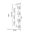
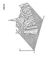
- FIG. 1 is a schematic plan view of a terrain based emitter 10 to be located relative to an observation point 12. It is assumed that emitter 10 rotates at a constant angular velocity of 30° per second and transmits pulsed radio frequency waves, e.g., at 1.344 gigahertz, with a pulse repetition rate, e.g., of 450 pulses per second. It is also assumed that emitter 10 has a directional radiation pattern with a narrow main beam or lobe, e.g., 2 to 3 ⁇ , and lower intensity side lobes.
- observation point 12 is not in a direct line of sight from emitter 10, i.e., observation point 12 is below the line of sight of emitter 10.
- Observation point 12 could be a low flying aircraft, a ground site, or a ship on water.
- the main beam of emitter 10 is not directed at observation point 12, some of the radio frequency energy from the side lobes reaches observation point 12 through ground reflections in a direct line, as depicted by the broken line in FIG. 1.
- Some of the radio frequency energy from the main beam also reaches observation point 12 after lateral reflection from terrain points, such as a point 14, as depicted by the unbroken line in FIG. 1.
- each pulse transmitted by emitter 10 reaches observation point 12 in the direct line path and thereafter reaches observation point 12 from a number of laterally reflective paths via various terrain points such as point 14.
- the time delays between the direct line pulse and the reflected pulses received at observation point 12 are indicative of the specific terrain points from which the delayed pulses are reflected. The longer the transmission path from emitter 10 to the terrain point of reflection and from there to observation point 12, the longer the time delay.
- the angular velocity at which emitter 10 rotates, its pulse repetition rate, and its direction from observation point 12 as a function of time can be determined.
- an extraordinarily large radio frequency energy pulse hereafter called Peak of Beam (POB)
- POB Peak of Beam
- the approximate angular position of the main beam of emitter 10 at the time of reception of each direct line pulse at observation point 12 can be inferred.
- This pulse is, in general, detectable even though the observer does not have direct line of sight to the emitter.
- emitter 10 is at an angle of 90°.
- point 0 represents observation point 12 and points E 1 and E 2 represent two emitter locations in the same direction from observation point 12 in a rectangular coordinate system having an I axis and a J axis.
- the coordinate system is defined so point 0 is at the origin and points E 1 and E 2 are on the J axis.
- a given pulse transmitted when the main beam is at an angle 8 and arriving at point 0 after a specified time delay would be reflected from a terrain point F 1 if emitter 10 were located at point E 1 and would be reflected from a terrain point F 2 if emitter 10 were located at point E 2 .
- FIG. 3 a single emitter location E is assumed.
- the distance between points E and 0, which defines the emitter location relative to observation point 12, is represented by a distance r. 8 is the angle of the main beam at the time of pulse transmission, I is one coordinate of a terrain point of reflection, and J is the other coordinate of the same terrain point of reflection.
- the locus of possible terrain points from which a reflected pulse could reach observation point 12 after a given time delay relative to a directly transmitted pulse is defined by an ellipse, as illustrated in FIG. 2, because the reflected transmission paths for all such terrain paths are the same.
- the delayed pulses received at observation point 12 correspond to ellipses increasing in size about points O and E with increasing time delay.
- This relationship is expressed by the equation: where the difference between each reflected transmission path, i.e., the sum of the distance from point E to a point (I, J) and the distance from such point (I, J) to point O, and the direct transmission path r equals D.
- the pulse time delay, r equals D divided by the speed of light.
- the coordinates of a point of reflection can be expressed in terms of the distance r, the angle of the main beam e , and D, the difference between the reflected and direct transmission paths from point E to point 0 as follows:
- the additional information about emitter location that can be obtained from delays due to terrain reflections for successive pulses from the emitter at the assumed pulse repetition rate is not significant. Therefore, only a fraction of the pulses transmitted by the emitter are ordinarily processed in the practice of the invention. By way of example, every 30th pulse transmitted by the emitter could be processed. Thus, for every 2 rotation of e, a set of time delay data is collected.
- FIG. 4 represents the directly transmitted pulses from the emitter received at the observation point.
- Large pulses 18 represent the POB pulses transmitted at twelve second intervals.
- Pulses 20 represent the pulses directly transmitted at successive angular positions of the emitter between the POB pulses. For the assumed emitter characteristics, 5,400 pulses 20 appear between successive pulses 18.
- Each 30th pulse 20 is processed to derive information about the emitter location during a sampling interval T, e.g., 600 microseconds, which is less than the period between pulses 20.
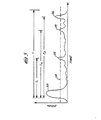
- FIG. 5 represents the radio frequency energy from a single pulse received at the observation point from the emitter.
- Pulse 20, as before, is the directly transmitted pulse.
- Pulses 22, 24 and 26 are reflections from terrain points in the region around the observation point.
- a broken horizontal line 28 represents the threshold for discriminating between reflected pulses and noise.
- the time delay between pulses 20 and 22 is represented as ⁇ 1 .
- the time delay between pulses 20 and 24 is represented as T2 .
- the time delay between pulses 20 and 26 is represented as r 3 . Delays ⁇ 1 , r 2 , and T3 are proportional to the transmission paths from the emitter to the observation points via the terrain points of reflection minus the direct transmission paths from the emitter to the observation point, i.e., r.
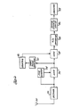
- FIG. 6 illustrates apparatus for collecting and processing the pulses from the emitter at the observation point.
- the radio frequency energy is intercepted by an antenna 30 and fed to a receiver 32, which converts the radio frequency energy to intermediate frequency.
- a Peak of Beam (POB) detector 34 controls a transmission gate 36. With reference to FIG. 4, detector 34 opens gate 36 for the interval between two successive POB pulses 18, during which a total of 5,400 directly transmitted pulses pass from receiver 32 through gate 36 to a transmission gate 38. These pulses are sensed by a direct pulse detector 40 and applied to a counter 42. After every 30th pulse, counter 42 opens gate 38 for a sampling interval T. The resulting sample as represented in FIG.
- POB Peak of Beam
- A/D converter 44 which digitizes a large number of samples, e.g., 3,000 samples at sampling intervals of 0.2 microsecond.
- the digitized samples are collected in a buffer storage device 46. After all the samples have been digitized they are transferred en masse to the memory of computer 48.
- the emitter is located by comparing the time delays of the reflected pulses with intervisibility data stored in the memory of computer 48. For each terrain point (I, J) in the region around the observation point there are stored in the memory of computer 48 a value of masking depth, Z i.e., the height above the terrain point that is visible from the observation point.
- a value of masking depth, Z i.e., the height above the terrain point that is visible from the observation point.
- Computer 48 compares terrain points of reflection (I, J) calculated from the measured times of arrival of a pulse transmitted by the emitter using equations (3) and (4) for candidate, i.e., assumed emitter locations, r, with the stored intervisibility data of terrain points (I, J). From this comparison, emitter locations corresponding to some terrain points (I, J) can be eliminated from consideration for the location of the emitter, because of the intervisibility data at such terrain points. For example, the masking depth at a particular terrain point might be so high that a reflection from such terrain point to the observation point would be virtually impossible.
- the masking depth at a particular terrain point might be near zero or the terrain point may be visible from the observation point so that a pulse transmitted from an assumed emitter location could have been reflected from that terrain point with the time delay, r, of the signal received at the observation point; such an assumed emitter location is a good candidate for acceptance as the actual emitter location.
- the evaluation of possible emitter locations, vis-a-vis the terrain points in the region around the observation point can be further refined.
- Intervisibility data represented by a block 50 namely I, J, and r
- reflected signal data represented by a block 52 namely D and e are evaluated, as represented by a block 54.
- the result of this evaluation provides a feasibility of candidate emitter locations at the terrain points in the region about the observation point, as represented by a block 56.
- other data can also be evaluated to refine the feasibility indication.
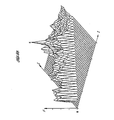
- FIGS. 8A to 8D represent plots of feasibility of various emitter locations.
- the feasibility (F) is indicated on the vertical axis, and the terrain points of candidate emitter locations from the observation point (0) are indicated on the J and I axes.
- the feasibility (F) for each terrain point is determined by counting the number of reflections received at the observation point that could have been transmitted from each terrain point, assuming that it was the emitter location, based on the comparison of time delays of reflected pulses with intervisibility data.
- the highest value of feasibility (F) occurs at the likely emitter location (E).
- FIGS. 8A to 8D depict a scoring function of the possible emitter locations based on the described comparison of the time delays of the reflected pulses with the intervisibility data. Different measures of scoring, i.e., evaluating these comparisons, could be employed to further refine the feasibility data.
Landscapes
- Engineering & Computer Science (AREA)
- Radar, Positioning & Navigation (AREA)
- Remote Sensing (AREA)
- Physics & Mathematics (AREA)
- General Physics & Mathematics (AREA)
- Computer Networks & Wireless Communication (AREA)
- Radar Systems Or Details Thereof (AREA)
- Position Fixing By Use Of Radio Waves (AREA)
- Measurement Of Velocity Or Position Using Acoustic Or Ultrasonic Waves (AREA)
Applications Claiming Priority (2)
| Application Number | Priority Date | Filing Date | Title |
|---|---|---|---|
| US07/195,740 US4882590A (en) | 1988-05-18 | 1988-05-18 | Method for locating a radio frequency emitter |
| US195740 | 1988-05-18 |
Publications (3)
| Publication Number | Publication Date |
|---|---|
| EP0342529A2 true EP0342529A2 (de) | 1989-11-23 |
| EP0342529A3 EP0342529A3 (de) | 1992-07-15 |
| EP0342529B1 EP0342529B1 (de) | 1996-01-10 |
Family
ID=22722592
Family Applications (1)
| Application Number | Title | Priority Date | Filing Date |
|---|---|---|---|
| EP89108528A Expired - Lifetime EP0342529B1 (de) | 1988-05-18 | 1989-05-11 | Verfahren zum Orten eines Radiofrequenz-Senders |
Country Status (10)
| Country | Link |
|---|---|
| US (1) | US4882590A (de) |
| EP (1) | EP0342529B1 (de) |
| JP (1) | JP2567094B2 (de) |
| KR (1) | KR920009025B1 (de) |
| AU (1) | AU602449B2 (de) |
| CA (1) | CA1328684C (de) |
| DE (1) | DE68925384T2 (de) |
| DK (1) | DK236589A (de) |
| ES (1) | ES2082758T3 (de) |
| IL (1) | IL89757A (de) |
Cited By (5)
| Publication number | Priority date | Publication date | Assignee | Title |
|---|---|---|---|---|
| RU2166199C2 (ru) * | 1999-06-01 | 2001-04-27 | Тамбовский военный авиационный инженерный институт | Способ определения горизонтальной дальности цели по излучению сканирующей рлс |
| WO2001067130A1 (en) * | 2000-03-08 | 2001-09-13 | University Corporation For Atmospheric Research | System for measuring characteristics of scatterers using spaced receiver remote sensors |
| WO2003001228A2 (en) | 2001-06-25 | 2003-01-03 | Harris Corporation | System and method for determining the location |
| RU2503969C1 (ru) * | 2012-05-03 | 2014-01-10 | Закрытое акционерное общество Научно-производственное предприятие "Спец-Радио" (ЗАО НПП "Спец-Радио") | Триангуляционно-гиперболический способ определения координат радиоизлучающих воздушных объектов в пространстве |
| RU2758832C1 (ru) * | 2020-12-10 | 2021-11-02 | Федеральное государственное бюджетное образовательное учреждение высшего образования "Санкт-Петербургский государственный университет телекоммуникаций им. проф. М.А. Бонч-Бруевича" | Способ определения местоположения сканирующей РЛС пассивным многолучевым пеленгатором |
Families Citing this family (11)
| Publication number | Priority date | Publication date | Assignee | Title |
|---|---|---|---|---|
| US4882590A (en) * | 1988-05-18 | 1989-11-21 | Hughes Aircraft Company | Method for locating a radio frequency emitter |
| US5181041A (en) * | 1991-07-02 | 1993-01-19 | Hughes Aircraft Company | Accurate location system using transponded and correlated LORAN signals |
| US5247311A (en) * | 1992-06-10 | 1993-09-21 | Sobocinski Richard S | Loro antenna and pulse pattern detection system |
| IL112186A (en) * | 1994-01-18 | 1998-09-24 | Honeywell Inc | A device for calculating inter-point vision |
| IL112237A (en) * | 1994-01-18 | 1998-03-10 | Honeywell Inc | System and method for evading threats to aircraft |
| RU2457505C2 (ru) * | 2010-09-30 | 2012-07-27 | Государственное образовательное учреждение высшего профессионального образования Томский государственный университет систем управления и радиоэлектроники (ТУСУР) | Устройство для определения местоположения работающей радиолокационной станции |
| RU2633962C1 (ru) * | 2016-07-14 | 2017-10-20 | Федеральное государственное бюджетное образовательное учреждение высшего образования "Санкт-Петербургский государственный университет телекоммуникаций им. проф. М.А. Бонч-Бруевича" | Способ определения местоположения сканирующей РЛС пассивным многолучевым пеленгатором |
| RU2657237C1 (ru) * | 2016-10-03 | 2018-06-09 | Общество с ограниченной ответственностью "Квадрокс" | Однопозиционный способ определения координат местоположения источников радиоизлучения |
| RU2741331C2 (ru) * | 2018-12-24 | 2021-01-25 | Федеральное государственное бюджетное образовательное учреждение высшего образования "Санкт-Петербургский государственный университет телекоммуникаций им. проф. М.А. Бонч-Бруевича" | Способ определения местоположения обзорной РЛС пассивным пеленгатором |
| RU2716145C1 (ru) * | 2019-04-24 | 2020-03-06 | Акционерное общество "Всероссийский научно-исследовательский институт "Градиент" (АО "ВНИИ "Градиент") | Способ пространственной локализации радиоизлучающих объектов |
| RU2741333C1 (ru) * | 2019-10-28 | 2021-01-25 | Федеральное государственное бюджетное образовательное учреждение высшего образования "Санкт-Петербургский государственный университет телекоммуникаций им. проф. М.А. Бонч-Бруевича" | Способ определения местоположения работающей РЛС пассивным многолучевым пеленгатором |
Family Cites Families (7)
| Publication number | Priority date | Publication date | Assignee | Title |
|---|---|---|---|---|
| US4386355A (en) * | 1980-03-31 | 1983-05-31 | The Boeing Company | System for determining the location of an airborne vehicle to the earth using a satellite-base signal source |
| US4370656A (en) * | 1980-10-27 | 1983-01-25 | General Dynamics, Pomona Division | Use of bistatic radar system for determining distance between airborne aircraft |
| US4438439A (en) * | 1981-04-29 | 1984-03-20 | The United States Of America As Represented By The Secretary Of The Army | Self-survey means |
| US4670757A (en) * | 1985-04-26 | 1987-06-02 | Eaton Corporation | Bistatic object location method |
| US4746924A (en) * | 1985-09-30 | 1988-05-24 | The Boeing Company | Apparatus and methods for locating a target utilizing signals generated from a non-cooperative source |
| US4828382A (en) * | 1986-04-18 | 1989-05-09 | Sundstrand Data Control, Inc. | Passive radio altimeter |
| US4882590A (en) * | 1988-05-18 | 1989-11-21 | Hughes Aircraft Company | Method for locating a radio frequency emitter |
-
1988
- 1988-05-18 US US07/195,740 patent/US4882590A/en not_active Expired - Fee Related
-
1989
- 1989-03-27 IL IL89757A patent/IL89757A/xx not_active IP Right Cessation
- 1989-05-11 EP EP89108528A patent/EP0342529B1/de not_active Expired - Lifetime
- 1989-05-11 ES ES89108528T patent/ES2082758T3/es not_active Expired - Lifetime
- 1989-05-11 DE DE68925384T patent/DE68925384T2/de not_active Expired - Fee Related
- 1989-05-12 AU AU34745/89A patent/AU602449B2/en not_active Ceased
- 1989-05-16 JP JP1120630A patent/JP2567094B2/ja not_active Expired - Lifetime
- 1989-05-16 DK DK236589A patent/DK236589A/da not_active Application Discontinuation
- 1989-05-17 CA CA000599943A patent/CA1328684C/en not_active Expired - Fee Related
- 1989-05-17 KR KR1019890006547A patent/KR920009025B1/ko not_active Expired
Cited By (7)
| Publication number | Priority date | Publication date | Assignee | Title |
|---|---|---|---|---|
| RU2166199C2 (ru) * | 1999-06-01 | 2001-04-27 | Тамбовский военный авиационный инженерный институт | Способ определения горизонтальной дальности цели по излучению сканирующей рлс |
| WO2001067130A1 (en) * | 2000-03-08 | 2001-09-13 | University Corporation For Atmospheric Research | System for measuring characteristics of scatterers using spaced receiver remote sensors |
| US6512996B1 (en) | 2000-03-08 | 2003-01-28 | University Corporation For Atmospheric Research | System for measuring characteristic of scatterers using spaced receiver remote sensors |
| WO2003001228A2 (en) | 2001-06-25 | 2003-01-03 | Harris Corporation | System and method for determining the location |
| EP1399752A4 (de) * | 2001-06-25 | 2008-09-03 | Harris Corp | System und verfahren zur bestimmung der position eines senders unter verwendung passiver reflektoren oder refraktoren als proxy-empfänger und unter verwendung von datenbankabfragen |
| RU2503969C1 (ru) * | 2012-05-03 | 2014-01-10 | Закрытое акционерное общество Научно-производственное предприятие "Спец-Радио" (ЗАО НПП "Спец-Радио") | Триангуляционно-гиперболический способ определения координат радиоизлучающих воздушных объектов в пространстве |
| RU2758832C1 (ru) * | 2020-12-10 | 2021-11-02 | Федеральное государственное бюджетное образовательное учреждение высшего образования "Санкт-Петербургский государственный университет телекоммуникаций им. проф. М.А. Бонч-Бруевича" | Способ определения местоположения сканирующей РЛС пассивным многолучевым пеленгатором |
Also Published As
| Publication number | Publication date |
|---|---|
| DE68925384T2 (de) | 1996-05-15 |
| DK236589D0 (da) | 1989-05-16 |
| JP2567094B2 (ja) | 1996-12-25 |
| DE68925384D1 (de) | 1996-02-22 |
| DK236589A (da) | 1989-11-19 |
| KR920009025B1 (ko) | 1992-10-12 |
| ES2082758T3 (es) | 1996-04-01 |
| AU602449B2 (en) | 1990-10-11 |
| CA1328684C (en) | 1994-04-19 |
| KR890017549A (ko) | 1989-12-16 |
| EP0342529B1 (de) | 1996-01-10 |
| JPH0264482A (ja) | 1990-03-05 |
| IL89757A (en) | 1993-01-31 |
| EP0342529A3 (de) | 1992-07-15 |
| US4882590A (en) | 1989-11-21 |
| AU3474589A (en) | 1989-11-23 |
Similar Documents
| Publication | Publication Date | Title |
|---|---|---|
| EP0342529A2 (de) | Verfahren zum Orten eines Radiofrequenz-Senders | |
| US6690317B2 (en) | Terrain database based ground return suppression | |
| US4438439A (en) | Self-survey means | |
| EP1260833B1 (de) | Methode zur Beseitigung der falschen reflektierten Ziele und zur automatischen Reflektorkartierung bei Sekundärüberwachungsradar | |
| EP0853769B1 (de) | System zum detektieren von mikro-burst | |
| CA2459944C (en) | Process and system for emitter location | |
| US4370656A (en) | Use of bistatic radar system for determining distance between airborne aircraft | |
| EP0466239B1 (de) | Vorrichtung zur Lokalisierung und Identifizierung von Transpondern | |
| US4429312A (en) | Independent landing monitoring system | |
| EP0763750B1 (de) | Radarsysteme. | |
| CA2176607C (en) | Radar system and method for detecting targets in clutter using target intensity and angular position | |
| US3716855A (en) | Glideslope position detection system for use with an independent aircraft landing monitor | |
| US4138660A (en) | Automated flash-bang method and apparatus for determining lightning stroke distances | |
| EP1123516B1 (de) | Adaptive verweilzeitsteuerung für zielverfolgung mittels radar | |
| US3364484A (en) | Low ambiguity radar scanning | |
| US5239310A (en) | Passive self-determined position fixing system | |
| US7274324B2 (en) | Apparatus and method of tracking objects in flight | |
| US4621267A (en) | Bearing intersection deghosting by altitude comparison system and methods | |
| RU2403588C2 (ru) | Способ радиолокационного обзора пространства (варианты) и комплекс радиолокационных станций для его реализации | |
| RU2092868C1 (ru) | Способ радиолокационного обнаружения и сопровождения объектов | |
| RU2128846C1 (ru) | Способ определения параметров наземных препятствий при полете летательных аппаратов на малой высоте | |
| RU2745108C1 (ru) | Способ определения разности расстояний до постановщика многократной ответно-импульсной помехи в активно-пассивной многопозиционной радиолокационной системе | |
| RU2196342C2 (ru) | Способ определения координат объектов при пассивной бистатической радиолокации | |
| US2703880A (en) | Radio object locating system | |
| JPH02136776A (ja) | レーダ装置 |
Legal Events
| Date | Code | Title | Description |
|---|---|---|---|
| PUAI | Public reference made under article 153(3) epc to a published international application that has entered the european phase |
Free format text: ORIGINAL CODE: 0009012 |
|
| 17P | Request for examination filed |
Effective date: 19890602 |
|
| AK | Designated contracting states |
Kind code of ref document: A2 Designated state(s): CH DE ES FR GB IT LI SE |
|
| PUAL | Search report despatched |
Free format text: ORIGINAL CODE: 0009013 |
|
| AK | Designated contracting states |
Kind code of ref document: A3 Designated state(s): CH DE ES FR GB IT LI SE |
|
| 17Q | First examination report despatched |
Effective date: 19940301 |
|
| GRAA | (expected) grant |
Free format text: ORIGINAL CODE: 0009210 |
|
| AK | Designated contracting states |
Kind code of ref document: B1 Designated state(s): CH DE ES FR GB IT LI SE |
|
| REF | Corresponds to: |
Ref document number: 68925384 Country of ref document: DE Date of ref document: 19960222 |
|
| ITF | It: translation for a ep patent filed | ||
| REG | Reference to a national code |
Ref country code: CH Ref legal event code: NV Representative=s name: ISLER & PEDRAZZINI AG PATENTANWAELTE |
|
| ET | Fr: translation filed | ||
| REG | Reference to a national code |
Ref country code: ES Ref legal event code: FG2A Ref document number: 2082758 Country of ref document: ES Kind code of ref document: T3 |
|
| PLBE | No opposition filed within time limit |
Free format text: ORIGINAL CODE: 0009261 |
|
| STAA | Information on the status of an ep patent application or granted ep patent |
Free format text: STATUS: NO OPPOSITION FILED WITHIN TIME LIMIT |
|
| 26N | No opposition filed | ||
| REG | Reference to a national code |
Ref country code: GB Ref legal event code: 732E |
|
| PGFP | Annual fee paid to national office [announced via postgrant information from national office to epo] |
Ref country code: FR Payment date: 19990412 Year of fee payment: 11 |
|
| PGFP | Annual fee paid to national office [announced via postgrant information from national office to epo] |
Ref country code: GB Payment date: 19990420 Year of fee payment: 11 |
|
| PGFP | Annual fee paid to national office [announced via postgrant information from national office to epo] |
Ref country code: DE Payment date: 19990426 Year of fee payment: 11 Ref country code: CH Payment date: 19990426 Year of fee payment: 11 |
|
| PGFP | Annual fee paid to national office [announced via postgrant information from national office to epo] |
Ref country code: SE Payment date: 19990427 Year of fee payment: 11 |
|
| PGFP | Annual fee paid to national office [announced via postgrant information from national office to epo] |
Ref country code: ES Payment date: 19990505 Year of fee payment: 11 |
|
| REG | Reference to a national code |
Ref country code: ES Ref legal event code: PC2A |
|
| REG | Reference to a national code |
Ref country code: FR Ref legal event code: TP Ref country code: FR Ref legal event code: CD Ref country code: FR Ref legal event code: CA |
|
| PG25 | Lapsed in a contracting state [announced via postgrant information from national office to epo] |
Ref country code: GB Free format text: LAPSE BECAUSE OF NON-PAYMENT OF DUE FEES Effective date: 20000511 |
|
| PG25 | Lapsed in a contracting state [announced via postgrant information from national office to epo] |
Ref country code: SE Free format text: LAPSE BECAUSE OF NON-PAYMENT OF DUE FEES Effective date: 20000512 Ref country code: ES Free format text: THE PATENT HAS BEEN ANNULLED BY A DECISION OF A NATIONAL AUTHORITY Effective date: 20000512 |
|
| PG25 | Lapsed in a contracting state [announced via postgrant information from national office to epo] |
Ref country code: LI Free format text: LAPSE BECAUSE OF NON-PAYMENT OF DUE FEES Effective date: 20000531 Ref country code: CH Free format text: LAPSE BECAUSE OF NON-PAYMENT OF DUE FEES Effective date: 20000531 |
|
| GBPC | Gb: european patent ceased through non-payment of renewal fee |
Effective date: 20000511 |
|
| REG | Reference to a national code |
Ref country code: CH Ref legal event code: PL |
|
| EUG | Se: european patent has lapsed |
Ref document number: 89108528.4 |
|
| PG25 | Lapsed in a contracting state [announced via postgrant information from national office to epo] |
Ref country code: FR Free format text: LAPSE BECAUSE OF NON-PAYMENT OF DUE FEES Effective date: 20010131 |
|
| PG25 | Lapsed in a contracting state [announced via postgrant information from national office to epo] |
Ref country code: DE Free format text: LAPSE BECAUSE OF NON-PAYMENT OF DUE FEES Effective date: 20010301 |
|
| REG | Reference to a national code |
Ref country code: FR Ref legal event code: ST |
|
| REG | Reference to a national code |
Ref country code: ES Ref legal event code: FD2A Effective date: 20020304 |
|
| PG25 | Lapsed in a contracting state [announced via postgrant information from national office to epo] |
Ref country code: IT Free format text: LAPSE BECAUSE OF NON-PAYMENT OF DUE FEES Effective date: 20050511 |