EP0342476B1 - Überladebrücke für Rampen - Google Patents
Überladebrücke für Rampen Download PDFInfo
- Publication number
- EP0342476B1 EP0342476B1 EP89108294A EP89108294A EP0342476B1 EP 0342476 B1 EP0342476 B1 EP 0342476B1 EP 89108294 A EP89108294 A EP 89108294A EP 89108294 A EP89108294 A EP 89108294A EP 0342476 B1 EP0342476 B1 EP 0342476B1
- Authority
- EP
- European Patent Office
- Prior art keywords
- bridge
- extension
- loading bridge
- loading
- section
- Prior art date
- Legal status (The legal status is an assumption and is not a legal conclusion. Google has not performed a legal analysis and makes no representation as to the accuracy of the status listed.)
- Expired - Lifetime
Links
Images
Classifications
-
- B—PERFORMING OPERATIONS; TRANSPORTING
- B65—CONVEYING; PACKING; STORING; HANDLING THIN OR FILAMENTARY MATERIAL
- B65G—TRANSPORT OR STORAGE DEVICES, e.g. CONVEYORS FOR LOADING OR TIPPING, SHOP CONVEYOR SYSTEMS OR PNEUMATIC TUBE CONVEYORS
- B65G69/00—Auxiliary measures taken, or devices used, in connection with loading or unloading
- B65G69/28—Loading ramps; Loading docks
- B65G69/2805—Loading ramps; Loading docks permanently installed on the dock
- B65G69/2811—Loading ramps; Loading docks permanently installed on the dock pivoting ramps
- B65G69/2817—Loading ramps; Loading docks permanently installed on the dock pivoting ramps with fluid-operated means
- B65G69/2829—Loading ramps; Loading docks permanently installed on the dock pivoting ramps with fluid-operated means extensible by sliding parts
Definitions
- the invention relates to a dock leveler for ramps according to the preamble of claim 1.
- a dock leveler is known from DE-A-2552433.
- the pivotable areas are designed as tongues that can be pushed in against a restoring force, in order to be able to adapt the dock leveler to platforms of different widths for the vehicles to be loaded or unloaded.
- This adjustment takes place automatically; the side walls of the vehicles grasp the tongue that stands in their way and push it backwards, while the parts of the extension located between the inserted tongues are supported on the platform.
- this possibility of adaptation is limited and only intended for vehicles which differ from one another in any case only by small width differences.
- the invention has for its object to design the dock levellers mentioned above with a support option over the entire width of the bridge that the effective width of the extension can be significantly reduced e.g. in such a way that even vehicles can be loaded or unloaded that have only one- or half-sided loading openings.
- the features of the characterizing part of claim 1 are used to achieve this object. Accordingly, the pivotable areas - preferably only a single area extending over about half the bridge width - are equipped with their own drive, which the two operating positions mentioned Ranges allowed.
- the effective width of the extension is reduced to about half; If the area is unfolded, the entire bridge width can be used, as is the case with bridges whose extension is rigid.
- the swivel cylinder is preferably connected to the lifting cylinder of the bridge plate in such a way that it is also pressurized when the bridge plate is lifted, that is to say when the lifting cylinder is acted upon, in order to fold it out.
- a valve switched into the supply line of the swivel cylinder allows a shut-off if the swiveling areas are not to be unfolded when the bridge plate is raised.
- the extension is expediently divided in such a way that one half is rigid in the above sense and the other half of the bridge is pivotable.
- the bridge plate 1 is pivotally mounted at its rear end about a horizontal axis on the ramp 2; the bridge plate 1 is located in a recess 3 of the ramp 2. In the rest position, the bridge plate 1 closes off with the surface 4 of the ramp 2, but it can be pivoted upwards - see FIG. 1 - or downwards into the recess 3 .
- an extension 6 which can be moved back and forth along this plate and can be moved in the sense of the double arrow 5, the working cylinder of which is not shown and which in the extended state according to FIG. 1 is on the platform of a truck or the like. lies on. Since the bridge plate 1 is supported on the platform via the extension 6, the bridge may follow changes in height of the platform.
- the bridge plate 1 is closed at the top by a plate 7, which laterally merges into side plates 8.
- the extension 6 is attached to a carriage 9, on which the aforementioned cylinder engages.
- the carriage 9 carries the front, continuous, extending over the bridge width part 10 of the extension 6, which on a Side of the bridge, namely over half the bridge width, into a section 11 rigidly connected to the part 10; on the other half of the extension 6, the part 10 is provided with a hinge 12 which serves to articulate an area 13 which, according to FIG. 1, is folded down and thereby extends approximately vertically downwards.
- a swivel cylinder 14 which grips it and acts on the slide 9 is provided. If the pivot cylinder 14 is not acted on, the region 13 folds downward into the vertical rest position according to FIG. 1 due to its own weight, which of course presupposes that the pressure medium located in the cylinder can flow away.
- the hydraulic system shown schematically by dashed lines in FIG. 2 provides a pump 15, a pressure line 16, a switching valve 17 for the swivel cylinder 14 and a lowering valve 18. If the pump 15 is turned on when the lowering valve 18 is closed and the switching valve 17 is open, the lifting cylinder 19 pivots the bridge plate 1 upwards. If the switching valve 17 is open, the pivot cylinder 14 is also acted on, so that the area 13 is unfolded, specifically into the position according to FIG. 2, the area 13 being able to fully assume the tasks of section 11 because it is articulated and can support itself stiffly at 20 on part 10.
- the area 13 remains in the vertical rest position according to FIG have a narrow loading door or only a flap which, for example, only extends over half the width of the truck or the like, it being understood that the bridge in this state also with, for example, only half-open doors can be used, which can be advantageous for thermal reasons.
- the bridge plate 1 drops due to its own weight when the pressure medium flows away. If the switching valve 17 is open, the area 13 folds down due to its own weight; however, if the switching valve 17 is closed, the area 13 remains in its approximately horizontal operating position while the bridge plate 1 sinks.
- the length of the pivotable area 13 should be approximately 2/3 of the total length of the extension 6 (lengths measured in the longitudinal direction of the bridge).
- the rear part 10 which extends over the bridge width is expediently box-shaped, at least in the section of the pivotable region 13; the carriage 9, which extends to the rear, is then also fastened to this part of the box, preferably in the form of beams which extend to the rear.
Landscapes
- Engineering & Computer Science (AREA)
- Mechanical Engineering (AREA)
- Auxiliary Methods And Devices For Loading And Unloading (AREA)
- Actuator (AREA)
Description
- Die Erfindung bezieht sich auf eine Überladebrücke für Rampen gemäß dem Oberbegriff des Anspruchs 1. Eine solche Überladebrücke ist aus DE-A-2552433 bekannt.
- Bei den bekannten Überladebrücken dieser Ausführung sind die schwenkbaren Bereiche als gegen eine Rückstellkraft einstossbare Zungen ausgebildet, um so die Überladebrücke an unterschiedlich breite Plattformen der zu be- bzw. entladenden Fahrzeuge anpassen zu können. Diese Anpassung erfolgt selbsttätig; die Seitenwände der Fahrzeuge erfassen die ihnen im Wege stehende Zunge und verdrängen diese nach hinten, während sich die zwischen den eingestossenen Zungen befindlichen Teile der Verlängerung auf der Plattform abstützen. Diese Anpassungsmöglichkeit ist jedoch beschränkt und nur für die sich ohnehin nur durch geringe Breitenunterschiede voneinander unterscheidenden Fahrzeuge bestimmt.
- Der Erfindung liegt die Aufgabe zugrunde, die eingangs erwähnten Überladebrücken so mit einer Abstützmöglichkeit über die gesamte Brückenbreite auszuführen, dass die wirksame Breite der Verlängerung erheblich vermindert werden kann z.B. in der Weise, dass sogar Fahrzeuge be- oder entladen werden können, die nur über ein- oder halbseitige Ladeöffnungen verfügen.
- Zur Lösung dieser Aufgabe dienen erfindungsgemäss die Merkmale des Kennzeichnenden Teils des Anspruchs 1. Demgemäss sind die schwenkbaren Bereiche ― vorzugsweise ist allerdings nur ein einziger Bereich sich über etwa eine Hälfte der Brückenbreite erstreckend vorgesehen ― mit einem eigenen Antrieb ausgestattet, der die beiden erwähnten Betriebsstellungen der Bereiche zulässt.
- Ist der Bereich nach unten geklappt, so ist die wirksame Breite der Verlängerung auf etwa die Hälfte verringert; ist der Bereich ausgeklappt, so kann die gesamte Brückenbreite ausgenutzt werden, wie dies bei Brücken der Fall ist, deren Verlängerung insgesamt starr ausgeführt ist.
- Der Schwenkzylinder wird vorzugsweise in der Weise mit dem Hubzylinder der Brückenplatte verbunden, dass er mit dem Anheben der Brückenplatte, also mit der Beaufschlagung des Hubzylinders ebenfalls unter Druck gesetzt wird, um so ein Ausklappen zu vollziehen. Ein in die Zuleitung des Schwenkzylinders eingeschaltetes Ventil erlaubt eine Absperrung, wenn mit dem Anheben der Brückenplatte die schwenkbaren Bereiche nicht ausgeklappt werden sollen.
- Zweckmässigerweise wird die Aufteilung der Verlängerung so vorgenommen, dass eine Hälfte im obigen Sinne starr und die andere Hälfte der Brücke schwenkbar ausgeführt wird.
- Weitere Einzelheiten der Erfindung werden anhand der Zeichnung erläutert, in der ein Ausführungsbeispiel der Erfindung dargestellt ist. Es zeigen:
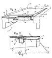
- Fig. 1
- eine Überladebrücke für Rampen in schaubildlicher Darstellung, und zwar bei ausgefahrener Verlängerung und
- Fig. 2
- einen Teillängsschnitt nach der Linie II-II von Fig. 1 unter Hinzufügung weiterer Bauteile der Überladebrücke allerdings bei eingezogener Verlängerung.
- Die Brückenplatte 1 ist an ihrem hinteren Ende um eine waagerechte Achse an der Rampe 2 schwenkbar gelagert; dabei befindet sich die Brückenplatte 1 in einer Ausnehmung 3 der Rampe 2. In der Ruhestellung schliesst die Brückenplatte 1 mit der Oberfläche 4 der Rampe 2 ab, sie kann jedoch nach oben ― siehe Fig. 1 ― oder nach unten in die Ausnehmung 3 geschwenkt werden. Am freien Ende der Brückenplatte 1 befindet sich eine längs zu dieser Platte hin und her bewegbare, im Sinne des Doppelpfeiles 5 verfahrbare Verlängerung 6, deren Arbeitszylinder nicht dargestellt ist und die im ausgefahrenen Zustand gemäss Fig. 1 auf der Plattform eines LKW od. dgl. aufliegt. Da sich die Brückenplatte 1 über die Verlängerung 6 auf der Plattform abstützt, folgt die Brücke evtl. Höhenänderungen der Plattform. Die Brückenplatte 1 wird oben durch ein Blech 7 abgeschlossen, das seitlich in Seitenbleche 8 übergeht.
- Die Verlängerung 6 ist an einem Schlitten 9 befestigt, an dem der erwähnte Arbeitszylinder angreift. Der Schlitten 9 trägt vorne das hintere, durchgehende, sich über die Brückenbreite erstreckende Teil 10 der Verlängerung 6, das auf einer Seite der Brücke, und zwar über die Hälfte der Brückenbreite hinweg in einen starr mit dem Teil 10 verbundenen Abschnitt 11 übergeht; auf der anderen Hälfte der Verlängerung 6 ist der Teil 10 mit einem Scharnier 12 versehen, das zur Anlenkung eines Bereiches 13 dient, der gemäss Fig. 1 nach unten geklappt ist und dabei sich etwa senkrecht nach unten erstreckt. Um den Bereich 13 von der Ruhestellung aus in die Betriebsstellung klappen zu können, wobei er mit dem Abschnitt 11 in einer Ebene liegt, ist ein ihn erfassender und an dem Schlitten 9 angreifender Schwenkzylinder 14 vorgesehen. Bei Nichtbeaufschlägung des Schwenkzylinders 14 klappt der Bereich 13 aufgrund seines Eigengewichtes nach unten in die senkrechte Ruhelage gemäss Fig. 1, was natürlich voraussetzt, dass das im Zylinder befindliche Druckmittel abfliessen kann.
- Die durch Strichelung in Fig. 2 schematisch wiedergegebene hydraulische Anlage sieht eine Pumpe 15, eine Druckleitung 16, ein Schaltventil 17 für den Schwenkzylinder 14 und ein Absenkventil 18 vor. Wird bei geschlossenem Absenkventil 18 die Pumpe 15 angestellt und ist dabei das Schaltventil 17 geöffnet, schwenkt der Hubzylinder 19 die Brückenplatte 1 nach oben. Ist das Schaltventil 17 geöffnet, so wird auch der Schwenkzylinder 14 beaufschlagt, so dass der Bereich 13 ausgeklappt wird, und zwar in die Stellung gemäss Fig. 2, wobei der Bereich 13 voll die Aufgaben des Abschnittes 11 mit übernehmen kann, weil er angelenkt ist und sich hinten steif bei 20 am Teil 10 abstützen kann.
- Wird das Schaltventil 17 nicht betätigt, so bleibt der Bereich 13 in der senkrechten Ruhelage gemäss Fig. 1. Dabei übernimmt der Abschnitt 11 alleine die Abstützung auf der Plattform, und die Brücke kann dabei bei solchen LKW od. dgl. benutzt werden, die nur über eine schmale Ladetür bzw. nur über eine Klappe verfügen, die sich z.B. nur über die halbe Breite des LKW od. dgl. erstreckt, wobei es sich versteht, dass die Brücke in diesem Zustand auch bei z.B. nur halbseitig geöffneten Türen verwendet werden kann, was aus wärmetechnischen Gründen von Vorteil sein kann.
- Bei geöffnetem Absenkventil 18 sinkt bei abfliessendem Druckmittel die Brückenplatte 1 aufgrund ihres Eigengewichtes ab. Ist dabei das Schaltventil 17 geöffnet, klappt der Bereich 13 aufgrund seines Eigengewichtes nach unten; ist das Schaltventil 17 hingegen geschlossen, verharrt der Bereich 13 in seiner etwa waagerechten Betriebsstellung, während die Brückenplatte 1 absinkt.
- Um bei einem nach unten geklappten Bereich 13 den starr angebrachten Abschnitt 11 weit über die zu be- bzw. entladende Plattform führen zu können, sollte die Länge des schwenkbaren Bereichs 13 etwa 2/3 der Gesamtlänge der Verlängerung 6 betragen (Längen in Brückenlängsrichtung gemessen).
- Um die Steifigkeit der Verlängerung 6 sicherzustellen, ist zweckmässigerweise der hintere, sich über die Brückenbreite erstreckende Teil 10 zumindest im Abschnitt des schwenkbaren Bereichs 13 kastenartig ausgeführt; an diesem Kastenteil ist dann auch der sich nach hinten erstreckende Schlitten 9 ― vorzugsweise in Form von sich nach hinten erstreckenden Trägern ― befestigt.
Claims (10)
Priority Applications (1)
| Application Number | Priority Date | Filing Date | Title |
|---|---|---|---|
| AT89108294T ATE67151T1 (de) | 1988-05-17 | 1989-05-09 | Ueberladebruecke fuer rampen. |
Applications Claiming Priority (4)
| Application Number | Priority Date | Filing Date | Title |
|---|---|---|---|
| DE19883816719 DE3816719A1 (de) | 1988-05-17 | 1988-05-17 | Ueberladebruecke fuer rampen |
| DE3816719 | 1988-05-17 | ||
| DE3839342A DE3839342A1 (de) | 1988-05-17 | 1988-11-22 | Ueberladebruecke fuer rampen |
| DE3839342 | 1988-11-22 |
Publications (3)
| Publication Number | Publication Date |
|---|---|
| EP0342476A2 EP0342476A2 (de) | 1989-11-23 |
| EP0342476A3 EP0342476A3 (en) | 1990-04-18 |
| EP0342476B1 true EP0342476B1 (de) | 1991-09-11 |
Family
ID=25868165
Family Applications (1)
| Application Number | Title | Priority Date | Filing Date |
|---|---|---|---|
| EP89108294A Expired - Lifetime EP0342476B1 (de) | 1988-05-17 | 1989-05-09 | Überladebrücke für Rampen |
Country Status (3)
| Country | Link |
|---|---|
| EP (1) | EP0342476B1 (de) |
| DE (2) | DE3839342A1 (de) |
| ES (1) | ES2026713T3 (de) |
Families Citing this family (3)
| Publication number | Priority date | Publication date | Assignee | Title |
|---|---|---|---|---|
| US6880301B2 (en) | 2001-03-06 | 2005-04-19 | Rite-Hite Holding Corporation | Pivotal and translational dock leveler lip |
| US7213285B2 (en) | 2004-08-12 | 2007-05-08 | Rite-Hite Holding Corporation | Pivotal and vertically translatable dock leveler lip |
| CN108869421B (zh) * | 2018-08-01 | 2023-10-20 | 甘肃工大舞台技术工程有限公司 | 一种液压驱动开合桥 |
Family Cites Families (4)
| Publication number | Priority date | Publication date | Assignee | Title |
|---|---|---|---|---|
| US2714735A (en) * | 1949-06-08 | 1955-08-09 | Margaret Redick Pennington | Adjustable loading ramp |
| CH576387A5 (en) * | 1974-04-02 | 1976-06-15 | Moser E Ag | Lorry loading ramp - has movable tongues on leading edge retracted by pivot arms into folded position |
| DE2552433A1 (de) * | 1975-11-22 | 1977-05-26 | Alten K | Ueberladebruecke fuer rampen |
| DE2851502A1 (de) * | 1978-11-29 | 1980-06-12 | Trepel Ag | Ueberfahrbruecke fuer rampen |
-
1988
- 1988-11-22 DE DE3839342A patent/DE3839342A1/de not_active Ceased
-
1989
- 1989-05-09 ES ES198989108294T patent/ES2026713T3/es not_active Expired - Lifetime
- 1989-05-09 EP EP89108294A patent/EP0342476B1/de not_active Expired - Lifetime
- 1989-05-09 DE DE8989108294T patent/DE58900275D1/de not_active Expired - Lifetime
Also Published As
| Publication number | Publication date |
|---|---|
| DE3839342A1 (de) | 1990-05-31 |
| EP0342476A2 (de) | 1989-11-23 |
| DE58900275D1 (de) | 1991-10-17 |
| EP0342476A3 (en) | 1990-04-18 |
| ES2026713T3 (es) | 1992-05-01 |
Similar Documents
| Publication | Publication Date | Title |
|---|---|---|
| DE7124021U (de) | Frachtladevorrichtung | |
| CH649970A5 (de) | Ueberfuehrvorrichtung an verladerampen. | |
| EP0342476B1 (de) | Überladebrücke für Rampen | |
| DE3301746C2 (de) | Klapptritt für Schienenfahrzeuge | |
| DE102010003378B4 (de) | Rampenauflage mit beweglicher Befestigung auf einer schwenkbaren Ladeklappe eines Fahrzeuges | |
| EP0484679B1 (de) | Zum Überbrücken von Eisenbahngleisen dienende Überfahrbrücke | |
| DE102007052349B4 (de) | Verladeeinrichtung | |
| DE3439651C1 (de) | UEberladebruecke fuer Rampen | |
| DE3708446C1 (de) | UEberladebruecke fuer Rampen | |
| DE3518727C2 (de) | ||
| EP0253263B1 (de) | Fahrzeug mit einem kastenförmigen Aufbau und einer Hubmechanik | |
| DE3816719C2 (de) | ||
| EP1882654B1 (de) | Überladebrücke mit Sicherheitssperre und Verfahren zum Betreiben der Überladebrücke | |
| EP1607366B1 (de) | Hubfahrzeug mit einer Scherenhubeinrichtung | |
| EP0319665A2 (de) | Behälter | |
| DE10205610B4 (de) | Lastfahrzeug mit Hubdach und verschließbarem Lastabteil | |
| DE3025625A1 (de) | Lastenaufzug, insbesondere fuer ro-ro-schiffe | |
| EP0114265B1 (de) | Klapptritt für Schienenfahrzeuge | |
| DE2218866A1 (de) | Vorrichtung zum Wegklappen der hinteren Bordwand an der Pritsche eines Kipperfahrzeuges | |
| DE19751623C1 (de) | Überladebrücke für Rampen | |
| DE1274156B (de) | Gedeckter Eisenbahngueterwagen, dessen Seitenwaende aus je zwei in geschlossenem Zustand in einer Ebene liegenden Schiebewandteilen bestehen | |
| DE2736184A1 (de) | Ueberfahrbruecke | |
| DE3336668A1 (de) | Kippaufbau an kraftfahrzeugen, insbesondere fuer mulden-hinterkipper | |
| DE19607274C2 (de) | Überladebrücke für Rampen | |
| DE29620266U1 (de) | Laderaum eines Kraftfahrzeuges |
Legal Events
| Date | Code | Title | Description |
|---|---|---|---|
| PUAI | Public reference made under article 153(3) epc to a published international application that has entered the european phase |
Free format text: ORIGINAL CODE: 0009012 |
|
| AK | Designated contracting states |
Kind code of ref document: A2 Designated state(s): AT BE CH DE ES FR GB GR IT LI LU NL SE |
|
| PUAL | Search report despatched |
Free format text: ORIGINAL CODE: 0009013 |
|
| AK | Designated contracting states |
Kind code of ref document: A3 Designated state(s): AT BE CH DE ES FR GB GR IT LI LU NL SE |
|
| RHK1 | Main classification (correction) |
Ipc: B65G 69/28 |
|
| 17P | Request for examination filed |
Effective date: 19900420 |
|
| 17Q | First examination report despatched |
Effective date: 19900823 |
|
| GRAA | (expected) grant |
Free format text: ORIGINAL CODE: 0009210 |
|
| AK | Designated contracting states |
Kind code of ref document: B1 Designated state(s): AT BE CH DE ES FR GB GR IT LI LU NL SE |
|
| PG25 | Lapsed in a contracting state [announced via postgrant information from national office to epo] |
Ref country code: GR Free format text: LAPSE BECAUSE OF FAILURE TO SUBMIT A TRANSLATION OF THE DESCRIPTION OR TO PAY THE FEE WITHIN THE PRESCRIBED TIME-LIMIT Effective date: 19910911 |
|
| REF | Corresponds to: |
Ref document number: 67151 Country of ref document: AT Date of ref document: 19910915 Kind code of ref document: T |
|
| REF | Corresponds to: |
Ref document number: 58900275 Country of ref document: DE Date of ref document: 19911017 |
|
| ITF | It: translation for a ep patent filed | ||
| ET | Fr: translation filed | ||
| GBT | Gb: translation of ep patent filed (gb section 77(6)(a)/1977) | ||
| REG | Reference to a national code |
Ref country code: ES Ref legal event code: FG2A Ref document number: 2026713 Country of ref document: ES Kind code of ref document: T3 |
|
| PG25 | Lapsed in a contracting state [announced via postgrant information from national office to epo] |
Ref country code: LU Free format text: LAPSE BECAUSE OF NON-PAYMENT OF DUE FEES Effective date: 19920531 |
|
| PLBE | No opposition filed within time limit |
Free format text: ORIGINAL CODE: 0009261 |
|
| STAA | Information on the status of an ep patent application or granted ep patent |
Free format text: STATUS: NO OPPOSITION FILED WITHIN TIME LIMIT |
|
| 26N | No opposition filed | ||
| EAL | Se: european patent in force in sweden |
Ref document number: 89108294.3 |
|
| REG | Reference to a national code |
Ref country code: FR Ref legal event code: TP |
|
| NLS | Nl: assignments of ep-patents |
Owner name: ALTEN GERAETEBAU GMBH |
|
| REG | Reference to a national code |
Ref country code: CH Ref legal event code: PUE Owner name: KURT ALTEN TRANSFER- ALTEN GERAETEBAU GMBH |
|
| REG | Reference to a national code |
Ref country code: GB Ref legal event code: 732E |
|
| REG | Reference to a national code |
Ref country code: ES Ref legal event code: PC2A |
|
| PGFP | Annual fee paid to national office [announced via postgrant information from national office to epo] |
Ref country code: DE Payment date: 20010723 Year of fee payment: 13 |
|
| REG | Reference to a national code |
Ref country code: GB Ref legal event code: IF02 |
|
| PGFP | Annual fee paid to national office [announced via postgrant information from national office to epo] |
Ref country code: GB Payment date: 20020426 Year of fee payment: 14 |
|
| PGFP | Annual fee paid to national office [announced via postgrant information from national office to epo] |
Ref country code: ES Payment date: 20020517 Year of fee payment: 14 |
|
| PGFP | Annual fee paid to national office [announced via postgrant information from national office to epo] |
Ref country code: FR Payment date: 20020522 Year of fee payment: 14 |
|
| PGFP | Annual fee paid to national office [announced via postgrant information from national office to epo] |
Ref country code: CH Payment date: 20020523 Year of fee payment: 14 |
|
| PGFP | Annual fee paid to national office [announced via postgrant information from national office to epo] |
Ref country code: SE Payment date: 20020524 Year of fee payment: 14 |
|
| PGFP | Annual fee paid to national office [announced via postgrant information from national office to epo] |
Ref country code: AT Payment date: 20020529 Year of fee payment: 14 |
|
| PGFP | Annual fee paid to national office [announced via postgrant information from national office to epo] |
Ref country code: NL Payment date: 20020531 Year of fee payment: 14 |
|
| PGFP | Annual fee paid to national office [announced via postgrant information from national office to epo] |
Ref country code: BE Payment date: 20020605 Year of fee payment: 14 |
|
| PG25 | Lapsed in a contracting state [announced via postgrant information from national office to epo] |
Ref country code: DE Free format text: LAPSE BECAUSE OF NON-PAYMENT OF DUE FEES Effective date: 20021203 |
|
| PG25 | Lapsed in a contracting state [announced via postgrant information from national office to epo] |
Ref country code: GB Free format text: LAPSE BECAUSE OF NON-PAYMENT OF DUE FEES Effective date: 20030509 Ref country code: AT Free format text: LAPSE BECAUSE OF NON-PAYMENT OF DUE FEES Effective date: 20030509 |
|
| PG25 | Lapsed in a contracting state [announced via postgrant information from national office to epo] |
Ref country code: SE Free format text: LAPSE BECAUSE OF NON-PAYMENT OF DUE FEES Effective date: 20030510 Ref country code: ES Free format text: LAPSE BECAUSE OF NON-PAYMENT OF DUE FEES Effective date: 20030510 |
|
| PG25 | Lapsed in a contracting state [announced via postgrant information from national office to epo] |
Ref country code: LI Free format text: LAPSE BECAUSE OF NON-PAYMENT OF DUE FEES Effective date: 20030531 Ref country code: CH Free format text: LAPSE BECAUSE OF NON-PAYMENT OF DUE FEES Effective date: 20030531 Ref country code: BE Free format text: LAPSE BECAUSE OF NON-PAYMENT OF DUE FEES Effective date: 20030531 |
|
| BERE | Be: lapsed |
Owner name: *ALTEN GERATEBAU G.M.B.H. Effective date: 20030531 |
|
| PG25 | Lapsed in a contracting state [announced via postgrant information from national office to epo] |
Ref country code: NL Free format text: LAPSE BECAUSE OF NON-PAYMENT OF DUE FEES Effective date: 20031201 |
|
| GBPC | Gb: european patent ceased through non-payment of renewal fee |
Effective date: 20030509 |
|
| EUG | Se: european patent has lapsed | ||
| REG | Reference to a national code |
Ref country code: CH Ref legal event code: PL |
|
| PG25 | Lapsed in a contracting state [announced via postgrant information from national office to epo] |
Ref country code: FR Free format text: LAPSE BECAUSE OF NON-PAYMENT OF DUE FEES Effective date: 20040130 |
|
| NLV4 | Nl: lapsed or anulled due to non-payment of the annual fee |
Effective date: 20031201 |
|
| REG | Reference to a national code |
Ref country code: FR Ref legal event code: ST |
|
| REG | Reference to a national code |
Ref country code: ES Ref legal event code: FD2A Effective date: 20030510 |
|
| PG25 | Lapsed in a contracting state [announced via postgrant information from national office to epo] |
Ref country code: IT Free format text: LAPSE BECAUSE OF NON-PAYMENT OF DUE FEES;WARNING: LAPSES OF ITALIAN PATENTS WITH EFFECTIVE DATE BEFORE 2007 MAY HAVE OCCURRED AT ANY TIME BEFORE 2007. THE CORRECT EFFECTIVE DATE MAY BE DIFFERENT FROM THE ONE RECORDED. Effective date: 20050509 |