EP0342467A2 - Dispositif d'épissage bout à bout des bandes de remplissage en élastomère appliquées sur les tringles de pneus - Google Patents
Dispositif d'épissage bout à bout des bandes de remplissage en élastomère appliquées sur les tringles de pneus Download PDFInfo
- Publication number
- EP0342467A2 EP0342467A2 EP89108236A EP89108236A EP0342467A2 EP 0342467 A2 EP0342467 A2 EP 0342467A2 EP 89108236 A EP89108236 A EP 89108236A EP 89108236 A EP89108236 A EP 89108236A EP 0342467 A2 EP0342467 A2 EP 0342467A2
- Authority
- EP
- European Patent Office
- Prior art keywords
- filler
- pliers
- primary
- systems
- respect
- Prior art date
- Legal status (The legal status is an assumption and is not a legal conclusion. Google has not performed a legal analysis and makes no representation as to the accuracy of the status listed.)
- Granted
Links
- 239000000945 filler Substances 0.000 title claims abstract description 76
- 239000011324 bead Substances 0.000 title claims abstract description 37
- 230000009471 action Effects 0.000 claims abstract description 7
- 241000254043 Melolonthinae Species 0.000 claims description 10
- 239000012530 fluid Substances 0.000 claims description 9
- 230000002093 peripheral effect Effects 0.000 claims description 3
- 238000000926 separation method Methods 0.000 claims description 3
- 230000000875 corresponding effect Effects 0.000 description 8
- 238000000034 method Methods 0.000 description 4
- 239000013536 elastomeric material Substances 0.000 description 3
- 239000004744 fabric Substances 0.000 description 2
- 230000009467 reduction Effects 0.000 description 2
- 230000007480 spreading Effects 0.000 description 2
- 230000015572 biosynthetic process Effects 0.000 description 1
- 230000006835 compression Effects 0.000 description 1
- 238000007906 compression Methods 0.000 description 1
- 238000001125 extrusion Methods 0.000 description 1
- 239000000463 material Substances 0.000 description 1
- 229910052751 metal Inorganic materials 0.000 description 1
- 230000008569 process Effects 0.000 description 1
- 230000002787 reinforcement Effects 0.000 description 1
Images

Classifications
-
- B—PERFORMING OPERATIONS; TRANSPORTING
- B29—WORKING OF PLASTICS; WORKING OF SUBSTANCES IN A PLASTIC STATE IN GENERAL
- B29D—PRODUCING PARTICULAR ARTICLES FROM PLASTICS OR FROM SUBSTANCES IN A PLASTIC STATE
- B29D30/00—Producing pneumatic or solid tyres or parts thereof
- B29D30/06—Pneumatic tyres or parts thereof (e.g. produced by casting, moulding, compression moulding, injection moulding, centrifugal casting)
- B29D30/48—Bead-rings or bead-cores; Treatment thereof prior to building the tyre
-
- B—PERFORMING OPERATIONS; TRANSPORTING
- B29—WORKING OF PLASTICS; WORKING OF SUBSTANCES IN A PLASTIC STATE IN GENERAL
- B29D—PRODUCING PARTICULAR ARTICLES FROM PLASTICS OR FROM SUBSTANCES IN A PLASTIC STATE
- B29D30/00—Producing pneumatic or solid tyres or parts thereof
- B29D30/06—Pneumatic tyres or parts thereof (e.g. produced by casting, moulding, compression moulding, injection moulding, centrifugal casting)
- B29D30/38—Textile inserts, e.g. cord or canvas layers, for tyres; Treatment of inserts prior to building the tyre
- B29D30/42—Endless textile bands without bead-rings
-
- B—PERFORMING OPERATIONS; TRANSPORTING
- B29—WORKING OF PLASTICS; WORKING OF SUBSTANCES IN A PLASTIC STATE IN GENERAL
- B29D—PRODUCING PARTICULAR ARTICLES FROM PLASTICS OR FROM SUBSTANCES IN A PLASTIC STATE
- B29D30/00—Producing pneumatic or solid tyres or parts thereof
- B29D30/06—Pneumatic tyres or parts thereof (e.g. produced by casting, moulding, compression moulding, injection moulding, centrifugal casting)
- B29D30/48—Bead-rings or bead-cores; Treatment thereof prior to building the tyre
- B29D2030/482—Applying fillers or apexes to bead cores
Definitions
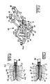
- the device 1 comprises two primary pliers systems 2, 2a respectively opposite and supported by respective arms 3, 3a which on their turn are engaged in a rotating manner, around a common axis, with a stationary sleeve 4 rigidly engaged with a collar 5 integral with a supporting frame 6, shown only in part.
- an arm 3, associated to the first pliers system 2 is fastened to a hub 7 splined on a driving small shaft 8, while the second arm 3a is fastened to a mobile sleeve 9 engaged in a rotating manner with the stationary sleeve 4 and engaging on its turn, in a rotating manner, the hub 7 of the first arm 3.
- a first gear wheel is splined, said gear wheel engaging when working with a second like gear wheel 16 splined on the pin 14 associated to the second clamping element 12.
- the gear wheels 15 and 16 mutually connect the clamping elements 11 and 12, so that to an angular rotation of one of the clamping elements, an angular rotation of equal entity but in opposite sense of the other clamping element corresponds.
- the deviation portions 20 of the first clamping element 11 forms a surface reduction with respect to the corresponding centering portion 21
- the deviation portion of the second clamping element 12 forms a surface relief countershaped to the above said reduction.
- the geometric characteristics and the dimensional ratios between the deviation portions and the centering portions must be time by time chosen according to the type of filler on which the splicing operation has to be effected.
- the contacting surfaces 19 are obtained on interchangeable plates 22 releasably fastened to the clamping elements 11 and 12 through threaded elements 23.
- the gripping elements 25, 26 have moreover respective continuations 33, 34 that, as better stressed in figure 2, diverge symmetrically when moving away from the stationary pin 27 to be rotatably engaged, at the respective free ends, with corresponding control rods 35, 36 mutually connected by a mobile pin 37.
- the mobile pin 37 is guided in a sliding manner by previous possible interposition of ball bearings or the like, through one or both the supporting plates 28, 29 along guiding slots 38 (only one is partially visible in figure 1) obtained in the plates themselves and extending according to the axis of alignment between the mobile pin and the stationary pin 27.
- the mobile pin 37 is translated along the guiding slots 38 through at least a return plate 39 provided with a shaped opening 40 in which a small block 41 connected on its turn to the mobile pin is guided in a sliding manner transversely of the development direction of the guiding slot 38.
- the return plate 39 is integral with a control pin 42 which crosses in a rotating manner the supporting plates 28, 29 and is rigidly engaged on the part opposite to the return plate, by a control lever 43; a driving fluid mechanics cylinder 44 (figure 1) connected to the first supporting plate 28 works on said control lever 43.
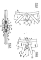
- the arms 3 and 4 are rotated angularly around their common pivoting axis to lead the pliers systems 2a and 2b from a rest position where, as shown in figure 3, are mutually spaced for permitting the engagement of the filler 45 by the clamping elements themselves, to an operative position in which, as shown in figure 4, the pliers systems are mutually approached to splice the ends 45a and 45b.
- the movement of the arms 3 and 4 can be obtained for instance through a not shown fluid mechanics cylinder, working between the driving small shaft 8 and the mobile sleeve 9 so as to rotate the one with respect to the other
- the pivoting axis of the arms 3 and 4 namely the axis around which the primary pliers systems 2, 2a rotate angularly, passes in proximity of the point in which the "V", configuration of the ends 45a and 45b converges.
- the above axis of rotation results lightly moved toward the center of the bead core with respect to the converging point of the "V".
- the primary pliers systems 2 and 2a rotate the one with respect to the other according to an angulation of figure 4 which is greater than the angle ⁇ formed by the ends 45a, 45b.
- the stem 44a of the fluid mechanics cylinder 44 is removed from the cylinder itself to cause, through the control pin 42, a rotation of the return plate 39 according to the direction of the arrow A of figure 2.
- the mobile pin 37 is moved along the guiding slots 38 toward the stationary pin 27, determining through the control rods 35, 36 a mutual spreading out of the continuations 33 and 34 presented by the gripping elements 25, 26.
- a mutual approaching of the gripping elements 25, 26 corresponds to the spreading out of the continuations33, 34. Consequently, the circumferential outer zones "E" of the ends 45a and 45b, mutually placed side by side, are compressed the one against the other between the contacting surfaces 30 of the gripping elements 25, 26.
- the lateral compression made on the ends of the filler by the ancillary pliers system eliminate the drawbacks given, in the known technique, by the unavoidable expansion of the filler section at the splicing zone.
Landscapes
- Engineering & Computer Science (AREA)
- Mechanical Engineering (AREA)
- Textile Engineering (AREA)
- Tyre Moulding (AREA)
Applications Claiming Priority (2)
| Application Number | Priority Date | Filing Date | Title |
|---|---|---|---|
| IT2062188 | 1988-05-18 | ||
| IT20621/88A IT1217631B (it) | 1988-05-18 | 1988-05-18 | Dispositivo per giuntare le estremita' di riempitivi elastomerici applicati su cerchietti di pneumatici |
Publications (3)
| Publication Number | Publication Date |
|---|---|
| EP0342467A2 true EP0342467A2 (fr) | 1989-11-23 |
| EP0342467A3 EP0342467A3 (fr) | 1991-11-06 |
| EP0342467B1 EP0342467B1 (fr) | 1993-06-09 |
Family
ID=11169677
Family Applications (1)
| Application Number | Title | Priority Date | Filing Date |
|---|---|---|---|
| EP89108236A Expired - Lifetime EP0342467B1 (fr) | 1988-05-18 | 1989-05-08 | Dispositif d'épissage bout à bout des bandes de remplissage en élastomère appliquées sur les tringles de pneus |
Country Status (6)
| Country | Link |
|---|---|
| US (2) | US4994136A (fr) |
| EP (1) | EP0342467B1 (fr) |
| JP (1) | JP2667905B2 (fr) |
| AR (1) | AR241877A1 (fr) |
| DE (1) | DE68906958T2 (fr) |
| IT (1) | IT1217631B (fr) |
Cited By (1)
| Publication number | Priority date | Publication date | Assignee | Title |
|---|---|---|---|---|
| WO2001017762A1 (fr) * | 1999-09-03 | 2001-03-15 | Bartell Machinery Systems, Llc | Dispositif de rouletage et de piquage de garnitures elastomeres sur des talons de pneumatiques |
Families Citing this family (13)
| Publication number | Priority date | Publication date | Assignee | Title |
|---|---|---|---|---|
| US5221409A (en) * | 1992-01-06 | 1993-06-22 | The Goodyear Tire & Rubber Company | Apparatus for butt splicing ply stock |
| JP2524059B2 (ja) * | 1992-09-29 | 1996-08-14 | 住友ゴム工業株式会社 | ビ―ド・エ―ペックス自動アッセンブル方法及びその装置 |
| JP4501265B2 (ja) * | 2000-09-25 | 2010-07-14 | 横浜ゴム株式会社 | ビードフィラーの圧着方法及びその装置 |
| JP2006186318A (ja) * | 2004-11-30 | 2006-07-13 | Nidec Tosok Corp | リードフレーム押出装置 |
| WO2008010293A1 (fr) | 2006-07-21 | 2008-01-24 | Toyo Tire & Rubber Co., Ltd. | Procédé et dispositif de production de talon de pneu |
| KR101015917B1 (ko) * | 2008-12-04 | 2011-02-23 | 한국타이어 주식회사 | 타이어 재단설비에서 카카스 원단에 부착되는 사이드 필링 테이프 부착장치 |
| FR2953444B1 (fr) * | 2009-12-09 | 2012-01-13 | Michelin Soc Tech | Procede de fabrication d'une tringle destinee a la realisation d'un pneumatique |
| NL2009946C2 (en) | 2012-12-10 | 2014-06-11 | Vmi Holland Bv | Tyre building machine for forming a bead-apex assembly. |
| NL2010201C2 (en) * | 2013-01-30 | 2014-08-04 | Vmi Holland Bv | Apparatus for forming an annular apex filler. |
| JP6228221B2 (ja) * | 2013-10-03 | 2017-11-08 | 不二精工株式会社 | ビードコアに対するフィラーの装着方法及び装着装置 |
| CN105682908B (zh) * | 2013-10-18 | 2019-11-05 | 巴特尔机械系统有限责任公司 | 用于夹持和处理轮胎胎圈三角胶条的系统及方法 |
| US10688745B2 (en) * | 2014-03-24 | 2020-06-23 | Fuji Seiko Co., Ltd. | Winding method and winding device for bead filler for tire |
| NL2027901B1 (en) * | 2021-04-01 | 2022-10-17 | Vmi Holland Bv | Method for positioning a strip for splicing, gripper for supplying said strip for splicing and tire building machine comprising said gripper |
Family Cites Families (15)
| Publication number | Priority date | Publication date | Assignee | Title |
|---|---|---|---|---|
| US2309305A (en) * | 1941-03-10 | 1943-01-26 | Carborundum Co | Abrasive article |
| US2565703A (en) * | 1948-05-22 | 1951-08-28 | Goodrich Co B F | Apparatus for splicing cushion tires |
| US2497461A (en) * | 1949-04-19 | 1950-02-14 | Dunlop Tire & Rubber Corp | Apparatus for splicing inner tubes of tires |
| US2647555A (en) * | 1950-12-12 | 1953-08-04 | Us Rubber Co | Method and apparatus for splicing |
| US2679888A (en) * | 1953-02-06 | 1954-06-01 | William K Bohon | Belt splicer |
| US3026569A (en) * | 1959-02-16 | 1962-03-27 | Philip B Keller | Method of fabricating omicron-rings |
| NL6802950A (fr) * | 1968-03-01 | 1969-09-03 | ||
| US3976534A (en) * | 1973-07-28 | 1976-08-24 | Howaldtswerke-Deutsche Werft Aktiengesellschaft Hamburg Und Kiel | Device for use in uniting the adjacent ends of radially split sealing rings |
| IT1115688B (it) * | 1977-12-15 | 1986-02-03 | Pirelli | Dispositivo per l'applicazione di un riempitivo elastomerico ad un cerchietto di pneumatico |
| IT1094441B (it) * | 1978-04-19 | 1985-08-02 | Pirelli | Miglioramenti ad applicatrice di riempitivo elastomerico a cerchietto di pneumatico |
| IT1124588B (it) * | 1979-10-09 | 1986-05-07 | Pirelli | Perfezionamenti nelle apparecchiatura per l'applicazione di riempitivi elastomerici a cerchietti di pneumatici |
| US4452660A (en) * | 1982-09-27 | 1984-06-05 | The Goodyear Tire & Rubber Company | Bead jamming or crimping apparatus |
| US4484975A (en) * | 1984-01-23 | 1984-11-27 | Mcelroy Manufacturing, Inc. | Hand held apparatus for joining small diameter plastic pipe |
| JPS6490736A (en) * | 1987-09-30 | 1989-04-07 | Sumitomo Rubber Ind | Apex mounting and its device |
| US5006385A (en) * | 1988-07-22 | 1991-04-09 | Signode Corporation | Strapping joint and method for forming same |
-
1988
- 1988-05-18 IT IT20621/88A patent/IT1217631B/it active
-
1989
- 1989-05-01 US US07/345,299 patent/US4994136A/en not_active Expired - Lifetime
- 1989-05-08 DE DE89108236T patent/DE68906958T2/de not_active Expired - Lifetime
- 1989-05-08 EP EP89108236A patent/EP0342467B1/fr not_active Expired - Lifetime
- 1989-05-16 AR AR89313932A patent/AR241877A1/es active
- 1989-05-18 JP JP1125478A patent/JP2667905B2/ja not_active Expired - Fee Related
-
1990
- 1990-12-27 US US07/634,715 patent/US5133817A/en not_active Expired - Lifetime
Cited By (1)
| Publication number | Priority date | Publication date | Assignee | Title |
|---|---|---|---|---|
| WO2001017762A1 (fr) * | 1999-09-03 | 2001-03-15 | Bartell Machinery Systems, Llc | Dispositif de rouletage et de piquage de garnitures elastomeres sur des talons de pneumatiques |
Also Published As
| Publication number | Publication date |
|---|---|
| EP0342467A3 (fr) | 1991-11-06 |
| JPH0220331A (ja) | 1990-01-23 |
| IT8820621A0 (it) | 1988-05-18 |
| AR241877A1 (es) | 1993-01-29 |
| JP2667905B2 (ja) | 1997-10-27 |
| EP0342467B1 (fr) | 1993-06-09 |
| US5133817A (en) | 1992-07-28 |
| US4994136A (en) | 1991-02-19 |
| DE68906958T2 (de) | 1994-01-20 |
| IT1217631B (it) | 1990-03-30 |
| DE68906958D1 (de) | 1993-07-15 |
Similar Documents
| Publication | Publication Date | Title |
|---|---|---|
| EP0342467B1 (fr) | Dispositif d'épissage bout à bout des bandes de remplissage en élastomère appliquées sur les tringles de pneus | |
| US3380115A (en) | Universal tire press loader | |
| US3674604A (en) | Tire building drum | |
| IE40287B1 (en) | Improvements in or relating to a method and apparatus for producing a cowtinuous band of rubberised fabric | |
| US5466182A (en) | Machine for scraping tires with controllable relative positioning of tire and work tool | |
| US5195411A (en) | Method and apparatus for correcting cut edge position | |
| JPH0243029A (ja) | 空気タイヤのビードコア上に弾性的フィラーを施すための装置 | |
| US3332820A (en) | Band support | |
| EP0325295B1 (fr) | Dispositif automatique pour la liaison transversale de feuilles en matière élastomère non vulcanisée | |
| US4584049A (en) | Radial tire forming blank supply apparatus | |
| GB1597199A (en) | Device for the application of elastomeric fillers on bead cores of pneumatic tyres | |
| US5100489A (en) | Method and apparatus for sticking belt-shaped member onto forming drum | |
| US2143443A (en) | Bending machine | |
| KR920009951B1 (ko) | 타이어성형기에 있어서의 트레드첩부(貼付)방법 | |
| US4278193A (en) | Glass breaking and separating apparatus and method | |
| US3423272A (en) | Stitching machine and tire builder | |
| US4565084A (en) | Method and a tool for bending the edge of thick sheet metal | |
| US2510715A (en) | Curing bag splicing machine | |
| US2489324A (en) | Splicing apparatus | |
| JP3583172B2 (ja) | 自動車用車輪のタイヤのフィッティング装置 | |
| US5379667A (en) | Pinch cutting method and apparatus | |
| US2971563A (en) | Method and apparatus for applying tread to rubber tires | |
| JPH0140630Y2 (fr) | ||
| US4682641A (en) | System for manufacture of high-lug tires | |
| CA1313349C (fr) | Dispositif de montage/demontage de pneus |
Legal Events
| Date | Code | Title | Description |
|---|---|---|---|
| PUAI | Public reference made under article 153(3) epc to a published international application that has entered the european phase |
Free format text: ORIGINAL CODE: 0009012 |
|
| AK | Designated contracting states |
Kind code of ref document: A2 Designated state(s): DE FR GB |
|
| PUAL | Search report despatched |
Free format text: ORIGINAL CODE: 0009013 |
|
| AK | Designated contracting states |
Kind code of ref document: A3 Designated state(s): DE FR GB |
|
| 17P | Request for examination filed |
Effective date: 19920416 |
|
| 17Q | First examination report despatched |
Effective date: 19921027 |
|
| GRAA | (expected) grant |
Free format text: ORIGINAL CODE: 0009210 |
|
| AK | Designated contracting states |
Kind code of ref document: B1 Designated state(s): DE FR GB |
|
| REF | Corresponds to: |
Ref document number: 68906958 Country of ref document: DE Date of ref document: 19930715 |
|
| ET | Fr: translation filed | ||
| PLBE | No opposition filed within time limit |
Free format text: ORIGINAL CODE: 0009261 |
|
| STAA | Information on the status of an ep patent application or granted ep patent |
Free format text: STATUS: NO OPPOSITION FILED WITHIN TIME LIMIT |
|
| 26N | No opposition filed | ||
| REG | Reference to a national code |
Ref country code: GB Ref legal event code: IF02 |
|
| PGFP | Annual fee paid to national office [announced via postgrant information from national office to epo] |
Ref country code: FR Payment date: 20060517 Year of fee payment: 18 |
|
| PGFP | Annual fee paid to national office [announced via postgrant information from national office to epo] |
Ref country code: GB Payment date: 20060525 Year of fee payment: 18 |
|
| GBPC | Gb: european patent ceased through non-payment of renewal fee |
Effective date: 20070508 |
|
| REG | Reference to a national code |
Ref country code: FR Ref legal event code: ST Effective date: 20080131 |
|
| PG25 | Lapsed in a contracting state [announced via postgrant information from national office to epo] |
Ref country code: GB Free format text: LAPSE BECAUSE OF NON-PAYMENT OF DUE FEES Effective date: 20070508 |
|
| PG25 | Lapsed in a contracting state [announced via postgrant information from national office to epo] |
Ref country code: FR Free format text: LAPSE BECAUSE OF NON-PAYMENT OF DUE FEES Effective date: 20070531 |
|
| PGFP | Annual fee paid to national office [announced via postgrant information from national office to epo] |
Ref country code: DE Payment date: 20080630 Year of fee payment: 20 |