EP0342415A2 - Russfilter für Dieselfahrzeuge - Google Patents
Russfilter für Dieselfahrzeuge Download PDFInfo
- Publication number
- EP0342415A2 EP0342415A2 EP89107750A EP89107750A EP0342415A2 EP 0342415 A2 EP0342415 A2 EP 0342415A2 EP 89107750 A EP89107750 A EP 89107750A EP 89107750 A EP89107750 A EP 89107750A EP 0342415 A2 EP0342415 A2 EP 0342415A2
- Authority
- EP
- European Patent Office
- Prior art keywords
- soot
- filter
- chamber
- channels
- soot filter
- Prior art date
- Legal status (The legal status is an assumption and is not a legal conclusion. Google has not performed a legal analysis and makes no representation as to the accuracy of the status listed.)
- Withdrawn
Links
Images
Classifications
-
- B—PERFORMING OPERATIONS; TRANSPORTING
- B01—PHYSICAL OR CHEMICAL PROCESSES OR APPARATUS IN GENERAL
- B01D—SEPARATION
- B01D46/00—Filters or filtering processes specially modified for separating dispersed particles from gases or vapours
- B01D46/24—Particle separators, e.g. dust precipitators, using rigid hollow filter bodies
- B01D46/2403—Particle separators, e.g. dust precipitators, using rigid hollow filter bodies characterised by the physical shape or structure of the filtering element
- B01D46/2418—Honeycomb filters
- B01D46/2451—Honeycomb filters characterized by the geometrical structure, shape, pattern or configuration or parameters related to the geometry of the structure
- B01D46/2474—Honeycomb filters characterized by the geometrical structure, shape, pattern or configuration or parameters related to the geometry of the structure of the walls along the length of the honeycomb
-
- F—MECHANICAL ENGINEERING; LIGHTING; HEATING; WEAPONS; BLASTING
- F01—MACHINES OR ENGINES IN GENERAL; ENGINE PLANTS IN GENERAL; STEAM ENGINES
- F01N—GAS-FLOW SILENCERS OR EXHAUST APPARATUS FOR MACHINES OR ENGINES IN GENERAL; GAS-FLOW SILENCERS OR EXHAUST APPARATUS FOR INTERNAL-COMBUSTION ENGINES
- F01N3/00—Exhaust or silencing apparatus having means for purifying, rendering innocuous, or otherwise treating exhaust
- F01N3/02—Exhaust or silencing apparatus having means for purifying, rendering innocuous, or otherwise treating exhaust for cooling, or for removing solid constituents of, exhaust
- F01N3/021—Exhaust or silencing apparatus having means for purifying, rendering innocuous, or otherwise treating exhaust for cooling, or for removing solid constituents of, exhaust by means of filters
- F01N3/0211—Arrangements for mounting filtering elements in housing, e.g. with means for compensating thermal expansion or vibration
-
- F—MECHANICAL ENGINEERING; LIGHTING; HEATING; WEAPONS; BLASTING
- F01—MACHINES OR ENGINES IN GENERAL; ENGINE PLANTS IN GENERAL; STEAM ENGINES
- F01N—GAS-FLOW SILENCERS OR EXHAUST APPARATUS FOR MACHINES OR ENGINES IN GENERAL; GAS-FLOW SILENCERS OR EXHAUST APPARATUS FOR INTERNAL-COMBUSTION ENGINES
- F01N3/00—Exhaust or silencing apparatus having means for purifying, rendering innocuous, or otherwise treating exhaust
- F01N3/02—Exhaust or silencing apparatus having means for purifying, rendering innocuous, or otherwise treating exhaust for cooling, or for removing solid constituents of, exhaust
- F01N3/021—Exhaust or silencing apparatus having means for purifying, rendering innocuous, or otherwise treating exhaust for cooling, or for removing solid constituents of, exhaust by means of filters
- F01N3/022—Exhaust or silencing apparatus having means for purifying, rendering innocuous, or otherwise treating exhaust for cooling, or for removing solid constituents of, exhaust by means of filters characterised by specially adapted filtering structure, e.g. honeycomb, mesh or fibrous
- F01N3/0222—Exhaust or silencing apparatus having means for purifying, rendering innocuous, or otherwise treating exhaust for cooling, or for removing solid constituents of, exhaust by means of filters characterised by specially adapted filtering structure, e.g. honeycomb, mesh or fibrous the structure being monolithic, e.g. honeycombs
-
- F—MECHANICAL ENGINEERING; LIGHTING; HEATING; WEAPONS; BLASTING
- F01—MACHINES OR ENGINES IN GENERAL; ENGINE PLANTS IN GENERAL; STEAM ENGINES
- F01N—GAS-FLOW SILENCERS OR EXHAUST APPARATUS FOR MACHINES OR ENGINES IN GENERAL; GAS-FLOW SILENCERS OR EXHAUST APPARATUS FOR INTERNAL-COMBUSTION ENGINES
- F01N3/00—Exhaust or silencing apparatus having means for purifying, rendering innocuous, or otherwise treating exhaust
- F01N3/02—Exhaust or silencing apparatus having means for purifying, rendering innocuous, or otherwise treating exhaust for cooling, or for removing solid constituents of, exhaust
- F01N3/021—Exhaust or silencing apparatus having means for purifying, rendering innocuous, or otherwise treating exhaust for cooling, or for removing solid constituents of, exhaust by means of filters
- F01N3/023—Exhaust or silencing apparatus having means for purifying, rendering innocuous, or otherwise treating exhaust for cooling, or for removing solid constituents of, exhaust by means of filters using means for regenerating the filters, e.g. by burning trapped particles
- F01N3/025—Exhaust or silencing apparatus having means for purifying, rendering innocuous, or otherwise treating exhaust for cooling, or for removing solid constituents of, exhaust by means of filters using means for regenerating the filters, e.g. by burning trapped particles using fuel burner or by adding fuel to exhaust
-
- F—MECHANICAL ENGINEERING; LIGHTING; HEATING; WEAPONS; BLASTING
- F01—MACHINES OR ENGINES IN GENERAL; ENGINE PLANTS IN GENERAL; STEAM ENGINES
- F01N—GAS-FLOW SILENCERS OR EXHAUST APPARATUS FOR MACHINES OR ENGINES IN GENERAL; GAS-FLOW SILENCERS OR EXHAUST APPARATUS FOR INTERNAL-COMBUSTION ENGINES
- F01N3/00—Exhaust or silencing apparatus having means for purifying, rendering innocuous, or otherwise treating exhaust
- F01N3/02—Exhaust or silencing apparatus having means for purifying, rendering innocuous, or otherwise treating exhaust for cooling, or for removing solid constituents of, exhaust
- F01N3/021—Exhaust or silencing apparatus having means for purifying, rendering innocuous, or otherwise treating exhaust for cooling, or for removing solid constituents of, exhaust by means of filters
- F01N3/031—Exhaust or silencing apparatus having means for purifying, rendering innocuous, or otherwise treating exhaust for cooling, or for removing solid constituents of, exhaust by means of filters having means for by-passing filters, e.g. when clogged or during cold engine start
- F01N3/032—Exhaust or silencing apparatus having means for purifying, rendering innocuous, or otherwise treating exhaust for cooling, or for removing solid constituents of, exhaust by means of filters having means for by-passing filters, e.g. when clogged or during cold engine start during filter regeneration only
-
- B—PERFORMING OPERATIONS; TRANSPORTING
- B01—PHYSICAL OR CHEMICAL PROCESSES OR APPARATUS IN GENERAL
- B01D—SEPARATION
- B01D2279/00—Filters adapted for separating dispersed particles from gases or vapours specially modified for specific uses
- B01D2279/30—Filters adapted for separating dispersed particles from gases or vapours specially modified for specific uses for treatment of exhaust gases from IC Engines
-
- F—MECHANICAL ENGINEERING; LIGHTING; HEATING; WEAPONS; BLASTING
- F01—MACHINES OR ENGINES IN GENERAL; ENGINE PLANTS IN GENERAL; STEAM ENGINES
- F01N—GAS-FLOW SILENCERS OR EXHAUST APPARATUS FOR MACHINES OR ENGINES IN GENERAL; GAS-FLOW SILENCERS OR EXHAUST APPARATUS FOR INTERNAL-COMBUSTION ENGINES
- F01N2240/00—Combination or association of two or more different exhaust treating devices, or of at least one such device with an auxiliary device, not covered by indexing codes F01N2230/00 or F01N2250/00, one of the devices being
- F01N2240/20—Combination or association of two or more different exhaust treating devices, or of at least one such device with an auxiliary device, not covered by indexing codes F01N2230/00 or F01N2250/00, one of the devices being a flow director or deflector
-
- F—MECHANICAL ENGINEERING; LIGHTING; HEATING; WEAPONS; BLASTING
- F01—MACHINES OR ENGINES IN GENERAL; ENGINE PLANTS IN GENERAL; STEAM ENGINES
- F01N—GAS-FLOW SILENCERS OR EXHAUST APPARATUS FOR MACHINES OR ENGINES IN GENERAL; GAS-FLOW SILENCERS OR EXHAUST APPARATUS FOR INTERNAL-COMBUSTION ENGINES
- F01N2270/00—Mixing air with exhaust gases
- F01N2270/08—Mixing air with exhaust gases for evacuation of exhaust gases, e.g. in tail-pipes
-
- F—MECHANICAL ENGINEERING; LIGHTING; HEATING; WEAPONS; BLASTING
- F01—MACHINES OR ENGINES IN GENERAL; ENGINE PLANTS IN GENERAL; STEAM ENGINES
- F01N—GAS-FLOW SILENCERS OR EXHAUST APPARATUS FOR MACHINES OR ENGINES IN GENERAL; GAS-FLOW SILENCERS OR EXHAUST APPARATUS FOR INTERNAL-COMBUSTION ENGINES
- F01N2330/00—Structure of catalyst support or particle filter
- F01N2330/02—Metallic plates or honeycombs, e.g. superposed or rolled-up corrugated or otherwise deformed sheet metal
-
- F—MECHANICAL ENGINEERING; LIGHTING; HEATING; WEAPONS; BLASTING
- F01—MACHINES OR ENGINES IN GENERAL; ENGINE PLANTS IN GENERAL; STEAM ENGINES
- F01N—GAS-FLOW SILENCERS OR EXHAUST APPARATUS FOR MACHINES OR ENGINES IN GENERAL; GAS-FLOW SILENCERS OR EXHAUST APPARATUS FOR INTERNAL-COMBUSTION ENGINES
- F01N2330/00—Structure of catalyst support or particle filter
- F01N2330/06—Ceramic, e.g. monoliths
-
- F—MECHANICAL ENGINEERING; LIGHTING; HEATING; WEAPONS; BLASTING
- F01—MACHINES OR ENGINES IN GENERAL; ENGINE PLANTS IN GENERAL; STEAM ENGINES
- F01N—GAS-FLOW SILENCERS OR EXHAUST APPARATUS FOR MACHINES OR ENGINES IN GENERAL; GAS-FLOW SILENCERS OR EXHAUST APPARATUS FOR INTERNAL-COMBUSTION ENGINES
- F01N2610/00—Adding substances to exhaust gases
- F01N2610/14—Arrangements for the supply of substances, e.g. conduits
- F01N2610/1453—Sprayers or atomisers; Arrangement thereof in the exhaust apparatus
-
- F—MECHANICAL ENGINEERING; LIGHTING; HEATING; WEAPONS; BLASTING
- F01—MACHINES OR ENGINES IN GENERAL; ENGINE PLANTS IN GENERAL; STEAM ENGINES
- F01N—GAS-FLOW SILENCERS OR EXHAUST APPARATUS FOR MACHINES OR ENGINES IN GENERAL; GAS-FLOW SILENCERS OR EXHAUST APPARATUS FOR INTERNAL-COMBUSTION ENGINES
- F01N3/00—Exhaust or silencing apparatus having means for purifying, rendering innocuous, or otherwise treating exhaust
- F01N3/08—Exhaust or silencing apparatus having means for purifying, rendering innocuous, or otherwise treating exhaust for rendering innocuous
- F01N3/10—Exhaust or silencing apparatus having means for purifying, rendering innocuous, or otherwise treating exhaust for rendering innocuous by thermal or catalytic conversion of noxious components of exhaust
- F01N3/24—Exhaust or silencing apparatus having means for purifying, rendering innocuous, or otherwise treating exhaust for rendering innocuous by thermal or catalytic conversion of noxious components of exhaust characterised by constructional aspects of converting apparatus
- F01N3/30—Arrangements for supply of additional air
-
- F—MECHANICAL ENGINEERING; LIGHTING; HEATING; WEAPONS; BLASTING
- F01—MACHINES OR ENGINES IN GENERAL; ENGINE PLANTS IN GENERAL; STEAM ENGINES
- F01N—GAS-FLOW SILENCERS OR EXHAUST APPARATUS FOR MACHINES OR ENGINES IN GENERAL; GAS-FLOW SILENCERS OR EXHAUST APPARATUS FOR INTERNAL-COMBUSTION ENGINES
- F01N3/00—Exhaust or silencing apparatus having means for purifying, rendering innocuous, or otherwise treating exhaust
- F01N3/08—Exhaust or silencing apparatus having means for purifying, rendering innocuous, or otherwise treating exhaust for rendering innocuous
- F01N3/10—Exhaust or silencing apparatus having means for purifying, rendering innocuous, or otherwise treating exhaust for rendering innocuous by thermal or catalytic conversion of noxious components of exhaust
- F01N3/24—Exhaust or silencing apparatus having means for purifying, rendering innocuous, or otherwise treating exhaust for rendering innocuous by thermal or catalytic conversion of noxious components of exhaust characterised by constructional aspects of converting apparatus
- F01N3/36—Arrangements for supply of additional fuel
-
- F—MECHANICAL ENGINEERING; LIGHTING; HEATING; WEAPONS; BLASTING
- F01—MACHINES OR ENGINES IN GENERAL; ENGINE PLANTS IN GENERAL; STEAM ENGINES
- F01N—GAS-FLOW SILENCERS OR EXHAUST APPARATUS FOR MACHINES OR ENGINES IN GENERAL; GAS-FLOW SILENCERS OR EXHAUST APPARATUS FOR INTERNAL-COMBUSTION ENGINES
- F01N3/00—Exhaust or silencing apparatus having means for purifying, rendering innocuous, or otherwise treating exhaust
- F01N3/08—Exhaust or silencing apparatus having means for purifying, rendering innocuous, or otherwise treating exhaust for rendering innocuous
- F01N3/10—Exhaust or silencing apparatus having means for purifying, rendering innocuous, or otherwise treating exhaust for rendering innocuous by thermal or catalytic conversion of noxious components of exhaust
- F01N3/24—Exhaust or silencing apparatus having means for purifying, rendering innocuous, or otherwise treating exhaust for rendering innocuous by thermal or catalytic conversion of noxious components of exhaust characterised by constructional aspects of converting apparatus
- F01N3/38—Arrangements for igniting
-
- F—MECHANICAL ENGINEERING; LIGHTING; HEATING; WEAPONS; BLASTING
- F02—COMBUSTION ENGINES; HOT-GAS OR COMBUSTION-PRODUCT ENGINE PLANTS
- F02B—INTERNAL-COMBUSTION PISTON ENGINES; COMBUSTION ENGINES IN GENERAL
- F02B3/00—Engines characterised by air compression and subsequent fuel addition
- F02B3/06—Engines characterised by air compression and subsequent fuel addition with compression ignition
-
- Y—GENERAL TAGGING OF NEW TECHNOLOGICAL DEVELOPMENTS; GENERAL TAGGING OF CROSS-SECTIONAL TECHNOLOGIES SPANNING OVER SEVERAL SECTIONS OF THE IPC; TECHNICAL SUBJECTS COVERED BY FORMER USPC CROSS-REFERENCE ART COLLECTIONS [XRACs] AND DIGESTS
- Y02—TECHNOLOGIES OR APPLICATIONS FOR MITIGATION OR ADAPTATION AGAINST CLIMATE CHANGE
- Y02A—TECHNOLOGIES FOR ADAPTATION TO CLIMATE CHANGE
- Y02A50/00—TECHNOLOGIES FOR ADAPTATION TO CLIMATE CHANGE in human health protection, e.g. against extreme weather
- Y02A50/20—Air quality improvement or preservation, e.g. vehicle emission control or emission reduction by using catalytic converters
-
- Y—GENERAL TAGGING OF NEW TECHNOLOGICAL DEVELOPMENTS; GENERAL TAGGING OF CROSS-SECTIONAL TECHNOLOGIES SPANNING OVER SEVERAL SECTIONS OF THE IPC; TECHNICAL SUBJECTS COVERED BY FORMER USPC CROSS-REFERENCE ART COLLECTIONS [XRACs] AND DIGESTS
- Y10—TECHNICAL SUBJECTS COVERED BY FORMER USPC
- Y10S—TECHNICAL SUBJECTS COVERED BY FORMER USPC CROSS-REFERENCE ART COLLECTIONS [XRACs] AND DIGESTS
- Y10S55/00—Gas separation
- Y10S55/30—Exhaust treatment
Definitions
- the invention relates to a soot filter for diesel vehicles with a filter body arranged in a housing with preferably conical exhaust gas supply and discharge connections with a plurality of channels parallel to one another, which are separated by thin filter walls, with half of the channels (raw gas channels) to the exhaust gas supply connector and the other half (clean gas channels) to the exhaust gas outlet are open and closed on the other side.
- soot filters which have already become known in the most varied of embodiments, all show the fundamental difficulty that the walls of the filter body become clogged over time due to the soot that is separated out, and so that a high back pressure builds up so that the filter no longer fulfills its effectiveness can. For this reason, soot filters of this type must always be freed from the separated soot particles at intervals, which in addition to chemical cleaning of the filter surface is usually achieved in practice in such a way that the filter inserts are burnt off.
- the invention is therefore based on the object of designing a soot filter of the type mentioned in such a way that a simpler, gentler and also more effective cleaning of the filter body is possible.
- the invention provides that the raw gas channels open into a soot chamber, which is provided with a closable soot outlet opening.
- soot filter While with conventional soot filters of the generic type, the raw gas channels at the end of the filter were simply closed, i.e. the raw gas channels were designed as blind holes (like the rest of the clean gas channels, in which, however, the opening is arranged on the outlet side and not on the exhaust gas inlet side) the soot filter according to the invention the closure is not provided directly at the end of the filter body, but behind all raw gas channels is one So-called soot chamber switched, which in turn can be closed, so that the conditions when working such a soot filter are effectively the same.
- the raw gas enters the raw gas channels and has to penetrate the walls to the clean gas channels, since it cannot escape through the soot chamber which is closed during operation.
- soot chamber When the filter walls pass through, the soot settles on the inner walls of the raw gas channels.
- the exhaust gas thus freed from soot and other solid contaminants passes through the clean gas channels into the exhaust line arranged downstream of the filter and is expelled there.
- the provision of the soot chamber according to the invention has the advantage, however, that to clean the raw gas channels, if necessary, it is only necessary to open the soot outlet opening of the soot chamber, so that the soot particles sitting on the walls in the channels are entrained and carried away by the exhaust gas.
- a soot chamber according to the invention can be achieved very advantageously in a development of the invention in such a way that a transverse wall forming an intermediate chamber together with the filter body is provided in the housing at a distance behind the filter body, and that the clean gas or raw gas channels pass through pipe sections passing through the intermediate chamber are connected to the end chamber behind the transverse wall.
- the design can either be such that the clean gas channels open into the end chamber connected to the exhaust pipe and the intermediate chamber forms the soot chamber, or else that the raw gas channels open into the end chamber forming the soot chamber via the pipe sections and that the intermediate chamber with one , preferably lateral, clean gas outlet is provided.
- the clean gas outlet for the intermediate chamber could also be formed in the usual way coaxially with the mostly cylindrical housing and in this case coaxially within the outlet line of the soot chamber.
- the design of a soot filter according to the invention can be such that a soot bag or the like can be connected behind the soot outlet opening, so that when the raw gas ducts are blown out, the soot collects in such a soot bag designed in a similar manner to a vacuum cleaner filter and is thus removed can.
- the soot settling in the raw gas channels can also be burned out in a known manner
- the possibility according to the invention of a direct passage through the raw gas channels brings a significant improvement in the burnout and in particular the possibility that any ash and other contaminant particles are also carried away and do not remain within the channels.
- a second soot filter with soot burning device is switched on in a bypass line between the soot outlet opening and a downstream point in the clean gas outlet pipe.
- the soot outlet opening of the soot chamber is opened and the soot is brought into the second soot filter by the engine exhaust gases, where it separates.
- the soot outlet line is then closed again, which takes only a very short time, so that the engine can easily continue to operate.
- the burning off then does not take place in the main soot filter itself, but in the second soot filter into which the soot had previously been blown.
- the soot filter is usually provided with a burn-off device, such a soot filter with a soot burn-off device, which contains air and fuel supply lines arranged in the area of the exhaust gas feed pipe and an ignition device, according to a further feature of the present invention, characterized in that the exhaust gas feed pipe is double-walled is designed as a fuel and / or air mixing and distribution chamber, the inner wall being provided with a plurality of burner openings distributed all around.
- the fuel supply line preferably a gas line
- the air supply lines preferably completely penetrate the distribution chamber, being provided with one-way or pulsed valves, so that they close when the engine is started by the exhaust gas pressure, whereas when the engine is switched off and the burner is switched on, they can open to supply air.
- an additional compressed air line can also be provided in order to achieve an increase in the flow through the filter when the filter burns.
- a fan for suctioning the exhaust gas is arranged downstream of the filter body.
- This blower can either comprise a suction blower connected to the side of the exhaust pipe, in which case a swiveling flap must be attached to the end of the exhaust pipe so that when the suction blower is switched on the flap closes and air cannot be drawn in for the exhaust end.
- a pressure blower emptying downstream into the exhaust pipe could also be provided, since such a pressure blower, which causes a strong air flow through the end of the exhaust pipe, conversely a static sub at the junction point pressure arises, which in turn provides for increased suction of the combustion gases when the soot burns off on the filter body, as a result of which an improved cleaner burning and in particular a more gentle burning is achieved by maintaining lower temperatures on the filter body.
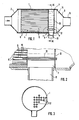
- a filter body 4 made of metal or ceramic is provided in the metallic housing 1 with conical exhaust gas supply nozzle 2 and exhaust gas discharge connector 3, which contains a plurality of channels parallel to one another.
- the gas entering the raw gas channels 5 passes through the thin filter walls to the adjacent clean gas channels, as a result of which the soot is deposited on the channel walls.
- the raw gas channels are not simply closed at the end, as are the clean gas channels at the other front end, but they all open into a soot chamber 7, which in turn can be locked by a closure device 8, shown schematically as a plate, and can also be opened if required.
- the locking device 8 is set so that the soot chamber 7 is closed, whereby in the end the same effect is achieved as if each of the raw gas channels were individually closed at the end.
- the raw gas has to pass through the thin filter walls 10 into the clean gas channels, with which the soot is separated.
- soot chamber according to the invention with the closable soot outlet opening 11 offers the possibility, when the raw gas channels are clogged, to blow them out over the soot chamber by opening the closure device 8, so that the exhaust gas flow takes the easier route and that means that it does not pass through the filter walls 10 , but flows through the raw gas channels at high speed and thereby tears the soot particles located therein and carries them out via the soot outlet opening 11, the further disposal to be described in more detail below.
- the provision of the soot chamber 7 in question requires pipe sections 12 for connecting the clean gas channels 6 to the discharge nozzle 3.
- the soot chamber 7 according to the invention also has considerable advantageous significance when the filter body is burned out, which cannot be completely avoided even with such a mechanical additional cleaning action.
- the soot particles attach themselves so firmly to the wall that they cannot simply be removed by blowing them out, but rather have to be burned off.
- the raw gas channels which are then open on both sides according to the invention a much faster flow can take place during the burning, so that on the one hand all ash particles can also be discharged and on the other hand it can be ensured that the walls of the filter body do not become so hot that they destroy them will.
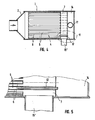
- FIGS. 4 and 5 show a modified embodiment in which it is not the intermediate chamber arranged between the filter body 4 and the transverse wall that forms the soot chamber, but the end chamber 14 that forms the soot chamber, while the intermediate chamber 7 that common collecting chamber for the clean gas channels, so that the clean gas outlet opening 15, which was arranged in Fig. 1 coaxially to the raw gas inlet opening, now appears as a laterally arranged outlet opening 15 'in Fig. 4.
- the clean gas lines are not connected to the end chamber 14 by the pipe pieces 12 attached, but instead the raw gas channels 5.
- the clean gas channels 6, open out into the intermediate chamber 7.
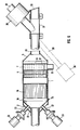
- FIG. 6 shows an expanded structure in which, in addition to the provision of a soot chamber, which in this case forms the intermediate chamber 7, with a side soot outlet opening 11 in front of the soot filter body 4, a gas diffuser 16, preferably designed as a honeycomb catalyst, is arranged.
- a gas diffuser 16 preferably designed as a honeycomb catalyst. This serves for a more even distribution of the exhaust gases and thus for a more even exposure to the soot filter body 4. At the same time, it serves for a better and more even burnout of the soot on the filter surfaces due to the more even distribution.
- the exhaust gas supply connection 2 is double-walled with an outer cone 17 and an inner cone 18.
- the fuel supply via the fuel supply line 19 takes place in the space between the two conical lateral surfaces 17 and 18, so that this space (see in particular FIG. 8) forms a mixing and distribution chamber 20 which has a plurality of burner openings 21 which cover the entire area
- the circumference of the inner cone 18 are distributed, causing a uniformly distributed flame distribution and thus a uniform burning.
- the air can also be introduced into this distribution chamber 20, in the exemplary embodiment shown it is provided that the air supply lines 22 with pulse air valves 23 are fully inserted through the double-walled exhaust gas supply nozzle.
- the Puls-Air valves are used to automatically close the air supply openings in normal engine operation (one-way valves). If, on the other hand, the engine is switched off and the soot filter is to be burnt out, a fuel electrode 24 is indicated when the fuel is supplied and the mixture is ignited with the aid of a schematically indicated the train of the fuel gas through the soot filter through the pulse air valves 23 opened so that the necessary combustion air is available.
- a temperature sensor is schematically shown at 25, which determines the combustion temperature, which can be used to control the fuel supply, in particular gas supply, and possibly also to introduce more or less compressed air into the combustion chamber in front of the filter to be burned off.
- a suction blower 26 can be provided which is flanged to the side of the exhaust line 27, a flap 28 pivotally hinged to the exhaust end closing the exhaust in the event of a fire, so that no incorrect air is sucked in from the rear can be, but the suction actually takes place through the filter body 4.
- the blower 26 is switched off and thus leaves the block 29, so that the exhaust gases can escape normally through the flap 28 by swinging up the exhaust.
- a pressure blower 26 'could also be used, which is indicated by the dashed line in FIG. which in the same way ensures better suction through the filter body, like a suction blower 26.
- FIG. 9 finally shows a tandem circuit in which the soot drain 11 of the in the engine main soot filter F1 lying exhaust pipe, a second soot filter F2 is connected, which is again connected to the exhaust line 27 in a bypass circuit via a swap flap arrangement V2.
- the valve V1 is closed, which in this case forms the closure device 8 in FIG. 1, the device according to FIG. 9 operates like the soot filter devices in FIGS. 1 to 8, although the blowers can of course also be provided if necessary, but for reasons of clarity have been omitted in FIG. 9.
- valve V1 In order to clean the main soot filter F1, the valve V1 is opened, the soot not being simply discharged, for example into a soot bag or the like, but rather entering the second soot filter F2. The valve V1 is then closed again, so that the main soot filter in the exhaust gas flow of the engine is functioning normally again and consequently the engine can continue to run, but now the soot is burned in the second soot filter F2 without impairing the engine function with the aid of a combustion device 32 which is only indicated schematically , which may include air supply line and fuel supply lines, igniters, etc.
- the soot filter F1 can of course also be cleaned by suction, which has already been mentioned several times.
- the invention is not restricted to the exemplary embodiment shown.
- a burning device is not absolutely necessary when a soot chamber is provided
- Soot filter bodies 4 it would be useful and possible, for example, in practice to provide instead of separate pipe pieces 12 that these connecting pieces 12, which pass through the intermediate chamber 7, are formed directly on the filter body 4, which is particularly easy if this is Press body is made of ceramic material.
Landscapes
- Engineering & Computer Science (AREA)
- Chemical & Material Sciences (AREA)
- Combustion & Propulsion (AREA)
- Mechanical Engineering (AREA)
- General Engineering & Computer Science (AREA)
- Physics & Mathematics (AREA)
- Geometry (AREA)
- Chemical Kinetics & Catalysis (AREA)
- Filtering Of Dispersed Particles In Gases (AREA)
- Processes For Solid Components From Exhaust (AREA)
Abstract
Description
- Die Erfindung bezieht sich auf einen Rußfilter für Dieselfahrzeuge mit einem in einem Gehäuse mit vorzugsweise konischen Abgaszu- und -abführstutzen angeordneten Filterkörper mit einer Vielzahl zueinander paralleler Kanäle, die durch dünne Filterwandungen getrennt sind, wobei eine Hälfte der Kanäle (Rohgaskanäle) zum Abgaszuführstutzen und die andere Hälfte (Reingaskanäle) zum Abgasabführstutzen hin offen und zur anderen Seite abgeschlossen sind.
- Derartige Rußfilter, die bereits in den unterschiedlichsten Ausführungsformen bekanntgeworden sind, zeigen alle die grundsätzliche Schwierigkeit, daß sich die Wandungen des Filterkörpers mit der Zeit durch den abgeschiedenen Ruß zusetzen und damit sich ein so hoher Gegendruck aufbaut, daß der Filter seine Wirksamkeit gar nicht mehr erfüllen kann. Aus diesem Grund müssen derartige Rußfilter grundsätzlich in Abständen wieder von den abgeschiedenen Rußteilchen befreit werden, was neben einer chemischen Reinigung der Filteroberfläche in der Praxis meist in der Weise erreicht wird, daß die Filtereinsätze abgebrannt werden.
- Da dieses Abbrennen im allgemeinen nicht gleichzeitig während der Funktion des Rußfilters erfolgen kann, sondern nur bei Stillstand des Motors, und das Abbrennen darüber hinaus wegen der Gefahr einer Überhitzung des häufig aus keramischem Werkstoff bestehenden Rußfilters auch die Gefahr eines Bruchs und damit einer Zerstörung des gesamten Filters mit sich bringt, besteht das Bedürfnis nach einer verbesserten einfacheren und schonenderen Filterreinigung. Darüber hinaus ergibt sich die Schwierigkeit, daß selbst mit dem Abbrand des Rußes die Probleme mit sich zusetzenden Filterflächen und erhöhtem Gegendruck noch nicht beseitigt sind, da die übrigbleibenden Verunreingiungsteilchen (Asche) nach wie vor im Filter verbleiben und somit den Gasdurchtritt des Abgases von den Rohgaskanälen zu den Reingaskanälen behindern.
- Der Erfindung liegt daher die Aufgabe zugrunde, einen Rußfilter der eingangs genannten Art so auszugestalten, daß ein einfacheres, schonenderes und auch wirksameres Reinigen des Filterkörpers möglich ist.
- Zur Lösung dieser Aufgabe ist erfindungsgemäß vorgesehen, daß die Rohgaskanäle in eine Rußkammer einmünden, die mit einer verschließbaren Ruß-Auslaßöffnung versehen ist.
- Während bei üblichen Rußfiltern der gattungsgemäßen Art die Rohgaskanäle am Ende des Filters einfach verschlossen waren, d.h. die Rohgaskanäle als Sackbohrungen ausgebildet waren (wie im übrigen auch die Reingaskanäle, bei denen allerdings die Öffnung auf der Auslaßseite und nicht der Abgaseintrittsseite angeordnet ist), ist bei dem erfindungsgemäßen Rußfilter der Verschluß nicht unmittelbar am Ende des Filterkörpers vorgesehen, sondern hinter alle Rohgaskanäle ist eine sog. Rußkammer geschaltet, die ihrerseits verschlossen werden kann, so daß wirkungsmäßig die Verhältnisse beim Arbeiten eines solchen Rußfilters die gleichen sind. Das Rohgas tritt in die Rohgaskanäle ein und muß die Wandungen zu den Reingaskanälen durchsetzen, da es ja durch die im Betrieb geschlossene Rußkammer nicht austreten kann. Beim Durchsetzen der Filterwandungen setzt sich der Ruß auf den Innenwänden der Rohgaskanäle ab. Das so von Ruß und anderen Feststoffverunreinigungen befreite Abgas gelangt über die Reingaskanäle in die stromabwärts vom Filter angeordnete Auspuffleitung und wird dort ausgestoßen. Das Vorsehen der erfindungsgemäßen Rußkammer hat aber den Vorteil, daß zum Reinigen der Rohgaskanäle im Bedarfsfall es lediglich eines Öffnens der Ruß-Auslaßöffnung der Rußkammer bedarf, damit die in den Kanälen auf den Wandungen sitzenden Rußpartikel durch das Abgas mitgerissen und ausgetragen werden. Dabei erfolgt selbstverständlich auch ein Austrag der Rußteilchen, die durch die Erschütterung und den Gasstrom von vorneherein in die Rußkammer gelangt sind und die durch ihre Anordnung in dieser Rußkammer bereits ein verringertes Zusetzen der Filterflächen des Filterkörpers zur Folge hatten und damit eine längere Standzeit des Rußfilters zur Folge haben. Unter Standzeit versteht man dabei die Zeit, die der Filter mit ausreichender Wirksamkeit arbeitet, ehe durch das Zusetzen der Filterflächen mit Ruß der Gegendruck zu hoch wird.
- Die Ausbildung einer erfindungsgemäßen Rußkammer läßt sich in Weiterbildung der Erfindung sehr vorteilhaft in der Weise erreichen, daß im Gehäuse in Abstand hinter dem Filterkörper eine, zusammen mit dem Filterkörper eine Zwischenkammer bildende Querwand vorgesehen ist, und daß die Reingas- oder Rohgaskanäle durch die Zwischenkammer durchsetzende Rohrstücke mit der Endkammer hinter der Querwand verbunden sind.
- Dabei kann die Ausbildung entweder so getroffen sein, daß die Reingaskanäle in die mit der Auspuffleitung verbundene Endkammer einmünden und die Zwischenkammer die Rußkammer bildet, oder aber auch, daß die Rohgaskanäle über die Rohrstücke in die die Rußkammer bildende Endkammer einmünden und daß die Zwischenkammer mit einem, vorzugsweise seitlichen, Reingasauslaß versehen ist. Gegebenenfalls könnte bei der letzteren Ausbildungsform der Reingasauslaß für die Zwischenkammer auch in üblicher Weise koaxial zum meist zylindrischen Gehäuse ausgebildet sein und in diesem Fall koaxial innerhalb der Auslaßleitung der Rußkammer. Zu diesem Zweck müßten dann allerdings die die Rohgaskanäle mit der Endkammer verbindenden Rohrstücke zur Endkammer hin konisch nach außen gebündelt werden, um in der Mitte Platz für die Reingasauslaßleitung zu bilden, was in der Praxis doch bauliche Schwierigkeiten bereitet, insbesondere wenn sehr viele Kanäle und damit auch sehr viele Rohrstücke vorzusehen sind.
- Die Ausbildung eines erfindungsgemäßen Rußfilters kann im einfachsten Fall so getroffen sein, daß hinter der Ruß-Auslaßöffnung ein Rußsack od. dgl. anschließbar ist, damit beim Ausblasen der Rohgaskanäle der Ruß sich in einem solchen, ähnlich einem Staubsaugerfilter ausgebildeten Rußsack sammelt und damit entfernt werden kann.
- Darüber hinaus kann selbstverständlich aber der in den Rohgaskanälen sich absetzende Ruß auch in bekannter Weise ausgebrannt werden, wobei die erfindungsgemäß gegebene Möglichkeit eines direkten Durchzugs durch die Rohgaskanäle, die ja bei den bislang bekannten Sackkanälen nicht gegeben war, eine erhebliche Verbesserung des Ausbrennens mit sich bringt und insbesondere auch die Möglichkeit, daß jegliche Asche und sonstige Verunreinigungsteilchen ebenfalls mit ausgetragen werden und nicht innerhalb der Kanäle verbleiben.
- Zum Austragen des Rußes durch Öffnen der Rußkammer kann schließlich auch vorgesehen sein, daß umschaltbar in einer Bypass-Leitung zwischen der Ruß-Auslaßöffnung und einer stromabwärtigen Stelle im Reingasauslaßrohr ein zweiter Rußfilter mit Rußabbrennvorrichtung eingeschaltet ist. Zum Reinigen des in die Motorabgasleitung eingeschalteten Hauptrußfilters wird die Rußauslaßöffnung der Rußkammer geöffnet und durch die Motorabgase der Ruß in den zweiten Rußfilter gebracht, wo er sich abscheidet. Anschließend wird - was ja nur eine sehr kurze Zeitdauer in Anspruch nimmt - die Ruß-Auslaßleitung wieder verschlossen, so daß der Motor ohne weiteres weiter in Betrieb bleiben kann. Das Abbrennen erfolgt dann nicht im eigentlichen Hauptrußfilter selbst, sondern in dem zweiten Rußfilter, in den der Ruß vorher eingeblasen worden war.
- In der Praxis wird man meist den Rußfilter mit einer Abbrennvorrichtung versehen, wobei ein solcher Rußfilter mit Rußabbrennvorrichtung, die im Bereich des Abgaszuführstutzens angeordnete Luft- und Brennstoffzuführleitung und eine Zündvorrichtung enthält, gemäß einem weiteren Merkmal der vorliegenden Erfindung dadurch gekennzeichnet ist, daß der Abgaszuführstutzen doppelwandig als Brennstoff- und/oder Luft-Misch- und Verteilkammer ausgebildet ist, wobei die Innenwand mit einer Vielzahl rundum verteilter Brenneröffnungen versehen ist.
- Während die Brennstoffzuführleitung, bevorzugt eine Gasleitung, nur die Außenwand des doppelwandigen Abgaszuführstutzens durchsetzt, um zu erreichen, daß der Brennstoff erst sich in der durch die Doppelwandigkeit gebildeten Misch- und Verteilkammer verteilt und somit ein gleichmäßiges Brennen über die gesamte Innenfläche und damit auch ein gleichmäßigeres Abbrennen des ihr gegenüberstehenden Filterkörpers stattfinden kann, durchsetzen die Luftzuführleitungen bevorzugt die Verteilkammer vollständig, wobei sie mit Einweg- oder Pulsairventilen versehen sind, so daß sie bei der Inbetriebnahme des Motors durch den Abgasdruck schließen, während bei abgeschaltetem Motor mit eingeschaltetem Brenner sie sich öffnen können, um Luft zuzuführen. Gegebenenfalls kann aber auch noch eine zusätzliche Druckluftleitung vorgesehen sein, um beim Abbrennen des Filters eine Verstärkung der Strömung durch den Filter hindurch zu erzielen.
- Eine derartige Strömungserhöhung und damit ein verbessertes Abbrennen des Rußes auf dem Filterkörper läßt sich schließlich in weiterer Ausgestaltung der Erfindung auch dadurch erzielen, daß stromabwärts vom Filterkörper ein Gebläse zum Durchsaugen des Abgases angeordnet ist. Dieses Gebläse kann dabei entweder ein seitlich an die Abgasleitung angeschlossenes Sauggebläse umfassen, in welchem Fall auf das Ende der Auspuffleitung eine schwenkbare Verschlußklappe aufgebracht sein muß, damit beim Einschalten des Sauggebläses die Klappe schließt und nicht Luft für das Auspuffende nachgesaugt werden kann. Alternativ hierzu könnte aber auch ein stromabwärts geneigt in die Abgasleitung einmündendes Druckgebläse vorgesehen sein, da durch ein solches Druckgebläse, welches eine starke Luftströmung durch das Ende des Auspuffrohrs bewirkt, umgekehrt an der Einmündungsstelle ein statischer Unter druck entsteht, der wiederum zur erhöhten Ansaugung der Verbrennungsgase beim Abbrennen des Rußes auf dem Filterkörper sorgt, wodurch ein verbessertes saubereres Abbrennen und insbesondere auch ein schonenderes Abbrennen durch Aufrechterhaltung niedrigerer Temperaturen auf dem Filterkörper erreicht wird. Diese Maßnahmen der besonderen Ausbildung der Rußabbrennvorrichtung durch die doppelwandige Ausbildung des Abgaszuführstutzens sowie die Erzielung eines besseren Abbrandes durch das Durchsaugen der Verbrennungsgase mit Hilfe eines Saug- oder speziell angeordneten Druckgebläses lassen sich ersichtlich auch bei herkömmlich ausgebildeten Rußfiltern sehr vorteilhaft einsetzen. Bevorzugt ist aber in jedem Fall das Vorsehen einer gemeinsamen Rußkammer für die auslaßseitigen Enden der Rohgaskanäle, da hierdurch die Reinigung sehr viel einfacher ist und vor allen Dingen auch beim Abbrennen ein sehr viel schonenderes gleichmäßigeres Abbrennen stattfinden kann, als es innerhalb von einseitig geschlossenen Kanälen möglich ist, wo auch die Gefahr örtlicher Hitzeüberlastungen und damit eines Brechens und einer Zerstörung des Filterkörpers gegeben wäre.
- Weitere Vorteile, Merkmale und Einzelheiten der Erfindung ergeben sich aus der nachfolgenden Beschreibung einiger Ausbildungsbeispiele sowie anhand der Zeichnung. Dabei zeigen:
- Fig. 1 einen schematischen Schnitt durch einen erfindungsgemäßen Rußfilter mit in eine Rußkammer einmündenden Rohgaskanälen,
- Fig. 2 eine vergrößerte Darstellung des Bereichs II in Fig. 1,
- Fig. 3 einen schematischen Querschnitt längs der Linie III-III in Fig. 1,
- Fig. 4 einen der Fig. 1 entsprechenden Schnitt durch eine abgewandelte Ausführungsform, bei der die Rußkammer die Endkammer des Filtergehäuses bildet,
- Fig. 5 eine vergrößerte Wiedergabe des Details V in Fig. 4,
- Fig. 6 einen Längsschnbitt durch einen Rußfilter mit Rußkammer und zusätzlichen Einrichtungen zur Vergleichmäßigung sowohl der Rußabscheidung als auch des Rußabbrandes,
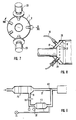
- Fig. 7 eine Stirnansicht der Anordnung nach Fig. 6 von links, wobei nicht alle einmündenden Anschlußleitungen und Bauteile mit eingezeichnet sind,
- Fig. 8 einen Schnitt längs der gewinkelten Linie VIII-VIII in Fig. 7, und
- Fig. 9 eine schematische Darstellung eines Doppelrußfilters, bei dem in Bypass-Schaltung an die Rußkammer des Hauptrußfilters ein zweiter Rußfilter angeschlossen ist.
- Im metallischen Gehäuse 1 mit konischen Abgaszuführstutzen 2 und Abgasabführstutzen 3 ist ein Filterkörper 4 aus Metall oder Keramik vorgesehen, der eine Vielzahl von zueinander parallelen Kanälen enthält. Diese bilden zur einen Hälfte Rohgaskanäle 5, die zum Abgaszuführstutzen 2 hin offen und zur anderen Seite hin abgeschlossen sind und zur anderen Hälfte Reingaskanäle 6, die zum Abgaszuführstutzen hin geschlossen sind, jedoch zum Abgasabführstutzen 3 hin offen. Das in die Rohgaskanäle 5 eintretende Gas durchsetzt die dünnen Filterwandungen zu den benachbarten Reingaskanälen, wodurch sich der Ruß auf den Kanalwandungen niederschlägt.
- Erfindungsgemäß sind nun die Rohgaskanäle nicht einfach am Ende abgeschlossen, so wie dies am anderen vorderen Ende die Reingaskanäle sind, sondern sie münden alle in eine Rußkammer 7 ein, die ihrerseits durch eine schematisch als Platte dargestellte Verschlußvorrichtung 8 abschließbar und bei Bedarf auch öffenbar ist. Im Betrieb ist die Abschließvorrichtung 8 so eingestellt, daß die Rußkammer 7 geschlossen ist, wodurch im Endeffekt die gleiche Wirkung erzielt ist, als wenn jeder der Rohgaskanäle einzeln am Ende verschlossen wäre. Im Endeffekt muß das Rohgas durch die dünnen Filterwände 10 in die Reingaskanäle, womit sich der Ruß abscheidet. Die erfindungsgemäße Rußkammer mit der verschließbaen Rußauslaßöffnung 11 bietet jedoch die Möglichkeit, bei einem Zusetzen der Rohgaskanäle diese über die Rußkammer hin auszublasen, indem die Verschlußvorrichtung 8 geöffnet wird, so daß der Abgasstrom den leichteren Weg geht und das bedeutet, er durchsetzt nicht die Filterwandungen 10, sondern durchströmt mit hoher Geschwindigkeit die Rohgaskanäle und reißt dabei die in diesen befindlichen Rußteilchen mit und trägt sie über die Ruß-Auslaßöffnung 11 aus, wobei die weitere Entsorgung weiter unten noch im einzelnen beschrieben werden soll. Das Vorsehen der angesprochenen Rußkammer 7 erfordert Rohrstücke 12 zur Verbindung der Reingaskanäle 6 mit dem Abführstutzen 3. Diese beidseits mit verjüngten Abschnitten versehenen Rohrstücke 12 werden einerseits in die Reingaskanäle eingesteckt und zum anderen in zu ihnen koaxial angeordnete Bohrungen der Querwand 13, die gemeinsam mit der rech ten Stirnkante des Filterkörpers 4 die Rußkammer 7 im Gehäuse 1 begrenzt.
- Neben dem einfachen Austragen des Rußes durch Ausblasen bei einer Öffnung der Ruß-Auslaßöffnung (11) hat die erfindungsgemäße Rußkammer 7 auch erhebliche vorteilhafte Bedeutung beim Ausbrennen des Filterkörpers, um das auch bei einer solchen mechanischen zusätzlichen Reinigungswirkung nicht vollständig herumzukommen ist. Teilweise setzen sich die Rußteilchen so fest an der Wandung an, daß sie nicht einfach durch Ausblasen herausgebracht werden können, sondern abgebrannt werden müssen. Bei den erfindungsgemäß ja dann beidseits offenen Rohgaskanälen kann beim Abbrennen ein sehr viel rascheres Durchströmen erfolgen, so daß zum einen ein Austrag auch aller Ascheteilchen mit erfolgen kann und zum anderen sichergestellt werden kann, daß die Wandungen des Filterkörpers nicht so heiß werden, daß sie zerstört werden.
- Im Gegensatz zum Ausführungsbeispiel nach den Figuren 1 bis 3 zeigen die Figuren 4 und 5 eine abgewandelte Ausführungsform, bei der nicht die zwischen dem Filterkörper 4 und der Querwand angeordnete Zwischenkammer die Rußkammer bildet, sondern die Endkammer 14 die Rußkammer bildet, während die Zwischenkammer 7 die gemeinsame Sammelkammer für die Reingaskanäle wird, so daß die Reingas-Auslaßöffnung 15, die in Fig. 1 koaxial zur Rohgas-Einlaßöffnung angeordnet war, nunmehr als seitlich angeordnete Auslaßöffnung 15′ in Fig. 4 erscheint. Zu diesem Zweck sind beim Ausführungsbeispiel nach den Figuren 4 und 5 nicht die Reingasleitungen durch die aufgesetzten Rohrstücke 12 mit der Endkammer 14 verbunden, sondern statt dessen die Rohgaskanäle 5. Die Reingaskanäle 6 münden dagegen frei in die Zwischenkammer 7 aus.
- Die Fig. 6 zeigt einen erweiterten Aufbau, bei dem zusätzlich zum Vorsehen einer in diesem Fall die Zwischenkammer 7 bildenden Rußkammer mit einer seitlichen Ruß-Auslaßöffnung 11 vor dem Ruß-Filterkörper 4 noch ein bevorzugt als Wabenkatalysator ausgebildeter Gasdiffusor 16 angeordnet ist. Dieser dient einer gleichmäßigeren Verteilung der Abgase und damit einer gleichmäßigeren Beaufschlagung des Ruß-Filterkörpers 4. Gleichzeitig dient er durch die gleichmäßigere Verteilung auch einem besseren und gleichmäßigeren Abbrand des Rußes auf den Filterflächen.
- Darüber hinaus ist bei diesem Ausführungsbeispiel vorgesehen, daß der Abgaszuführstutzen 2 doppelwandig mit einem Außenkonus 17 und einem Innenkonus 18 ausgebildet ist. Die Brennstoffzuführung über die Brennstoffzuführleitung 19 erfolgt in den Zwischenraum zwischen den beiden Konusmantelflächen 17 und 18, so daß dieser Zwischenraum (vergl. insbesondere Fig. 8) eine Misch- und Verteilkammer 20 bildet, die über eine Vielzahl von Brenneröffnungen 21, die über den gesamten Umfang des inneren Konus 18 verteilt sind, eine gleichmäßige rundum angeordnete Flammenverteilung und damit ein gleichmäßiges Abbrennen bewirken. Obgleich in Sonderfällen auch die Luft in diese Verteilkammer 20 eingeleitet werden kann, ist im gezeigten Ausführungsbeispiel abweichend davon vorgesehen, daß die Luftzuführleitungen 22 mit aufgesetzten Puls-Air-Ventilen 23 den doppelwandigen Abgaszuführstutzen ganz durchsetzen. Die Puls-Air-Ventile dienen dazu, im normalen Motorbetrieb ein selbständiges Abschließen der Luftzuführöffnungen zu bewirken (Einweg-Ventile). Wird dagegen der Motor abgeschaltet und soll der Rußfilter ausgebrannt werden, so werden beim Zuführen des Brennstoffes und dem Zünden des Gemisches mit Hilfe einer schematisch angedeuteten Brennelektrode 24 durch den Zug des Brenngases durch den Rußfilter hindurch die Puls-Air-Ventile 23 geöffnet, so daß die notwendige Verbrennungsluft zur Verfügung steht.
- Bei 25 ist schematisch ein Temperaturfühler dargestellt, der die Verbrennungstemperatur ermittelt, die zur Steuerung der Brennstoffzufuhr, insbesondere Gaszufuhr, und ggfs. auch dazu dienen kann, mehr oder weniger Druckluft in den Verbrennungsraum vor dem abzubrennenden Filter einzubringen.
- Zur Unterstützung des Brenngasstroms beim Ausbrennen des Filterkörpers 4 durch den Filterkörper hindurch kann ein Sauggebläse 26 vorgesehen sein, welches seitlich an die Auspuffleitung 27 angeflanscht ist, wobei eine schwenkbar am Auspuffende angelenkte Klappe 28 im Abbrennfall den Auspuff schließt, so daß keine Fehlluft von rückwärts eingesaugt werden kann, sondern das Einsaugen tatsächlich durch den Filterkörper 4 hindurch erfolgt. Beim normalen Motorbetrieb ist das Gebläse 26 ausgeschaltet und somit der Aus laß 29 blokkiert, so daß die Auspuffgase unter Nach-oben-Schwenken der Klappe 28 normal über den Auspuff austreten können. Anstelle eines Sauggebläses könnte ggfs. auch, was in Fig. 6 strichliert angedeutet ist, ein Druckgebläse 26′ verwendet werden, welches über eine stromabwärts geneigte Leitung 30 in das Auspuffrohr 27 einmündet und infolge der Strömungsgeschwindigkeit einen Unterdruck im Einmündungsbereich in das Auspuffrohr 27 bildet, der in gleicher Weise für ein besseres Durchsaugen durch den Filterkörper sorgt, wie ein Sauggebläse 26. Bei Verwenden eines solchen Druckgebläses mit besonderer Neigung der Einblasleitung 30 wäre im übrigen eine schwenkbar angelenkte Klappe 28 nicht erforderlich. Die Fig. 9 zeigt schließlich eine Tandemschaltung, bei der an den Rußablaß 11 des in der Motor auspuffleitung liegenden Haupt-Rußfilters F1 ein zweiter Rußfilter F2 angeschlossen ist, der über eine Wechselklappenanordnung V2 wieder an die Auspuffleitung 27 in Bypass-Schaltung angelegt ist. Bei geschlossenem Ventil V1, welches in diesem Fall die Verschlußvorrichtung 8 in Fig. 1 bildet, arbeitet die Vorrichtung gemäß Fig. 9 wie die Rußfiltervorrichtungen in den Figuren 1 bis 8, wobei ggfs. selbstverständlich auch die Gebläse vorgesehen sein können, die jedoch aus Übersichtlichkeitsgründen in Fig. 9 weggelassen worden sind. Zum Reinigen des Haupt-Rußfilters F1 wird das Ventil V1 geöffnet, wobei der Ruß nicht einfach ausgetragen wird, beispielsweise in einen Rußbeutel od.dgl., sondern in den zweiten Rußfilter F2 gelangt. Anschließend wird das Ventil V1 wieder geschlossen, so daß der Hauptrußfilter im Abgasstrom des Motors wieder normal funktioniert und demzufolge auch der Motor weiterlaufen kann, während nunmehr aber der Ruß ohne Beeinträchtigung der Motorfunktion im zweiten Rußfilter F2 mit Hilfe einer nur schematisch angedeuteten Abbrennvorrichtung 32 verbrannt wird, die Luftzuführleitung und Brennstoffzuführleitungen, Zünder usw. umfassen kann. Anstelle des Ableitens des Rußes aus dem Haupt-Rußfilter F1 über den zweiten Rußfilter F2 und der daraus resultierenden Möglichkeit des Abbrennes des Rußes während der Fahrt, kann der Rußfilter F1 selbstverständlich auch durch Absaugen gereinigt werden, was ja bereits mehrfach angesprochen worden ist.
- Die Erfindung ist nicht auf das dargestellte Ausführungsbeispiel beschränkt. Neben der Möglichkeit des Vorsehens anderer Abbrennvorrichtungen (wobei ja eine Abbrennvorrichtung bei Vorsehen einer Rußkammer gar nicht unbedingt zwingend erforderlich ist), sowie der Möglichkeit der Verwendung anderer Konfigurationen von Ruß-Filterkörpern 4 wäre es beispielsweise in der Praxis auch zweckmäßig und möglich, anstelle von gesonderten Rohrstücken 12 vorzusehen, daß diese Verbindungsstücke 12, die die Zwischenkammer 7 durchsetzen, unmittelbar am Filterkörper 4 mit angeformt sind, was besonders einfach möglich ist, wenn dieser als Preßkörper aus keramischem Werkstoff hergestellt ist.
Claims (13)
Applications Claiming Priority (2)
| Application Number | Priority Date | Filing Date | Title |
|---|---|---|---|
| DE8806440U | 1988-05-17 | ||
| DE8806440U DE8806440U1 (de) | 1988-05-17 | 1988-05-17 | Rußfilter für Dieselfahrzeuge |
Publications (2)
| Publication Number | Publication Date |
|---|---|
| EP0342415A2 true EP0342415A2 (de) | 1989-11-23 |
| EP0342415A3 EP0342415A3 (de) | 1990-08-08 |
Family
ID=6824102
Family Applications (1)
| Application Number | Title | Priority Date | Filing Date |
|---|---|---|---|
| EP89107750A Withdrawn EP0342415A3 (de) | 1988-05-17 | 1989-04-28 | Russfilter für Dieselfahrzeuge |
Country Status (3)
| Country | Link |
|---|---|
| US (1) | US5019142A (de) |
| EP (1) | EP0342415A3 (de) |
| DE (1) | DE8806440U1 (de) |
Cited By (4)
| Publication number | Priority date | Publication date | Assignee | Title |
|---|---|---|---|---|
| FR2693382A1 (fr) * | 1992-07-07 | 1994-01-14 | Rhone Poulenc Chimie | Filtre pour épuration des fumées de moteurs, notamment de moteurs diesel. |
| US6576032B2 (en) | 1999-05-28 | 2003-06-10 | Emitec Gesellschaft Fuer Emissionstechnologie Mbh | Particle filter of metal foil and process for producing a particle filter |
| WO2003064829A1 (de) * | 2002-01-31 | 2003-08-07 | Burger Ag | Einrichtung zum zurückhalten von verbrennungsrückständen |
| EP1431529A1 (de) * | 2002-12-20 | 2004-06-23 | DEUTZ Aktiengesellschaft | Verfahren und Vorrichtung zur Anhebung oder Absenkung der Abgastemperatur bei Dieselmotoren |
Families Citing this family (24)
| Publication number | Priority date | Publication date | Assignee | Title |
|---|---|---|---|---|
| US5250090A (en) * | 1992-06-01 | 1993-10-05 | Hps Merrimack, Inc. | Separation devices |
| CA2481774A1 (en) * | 2002-04-12 | 2003-10-23 | Illinois Valley Holding Company | Apparatus and method for filtering particulate and reducing nox emissions |
| US7090714B2 (en) * | 2002-06-17 | 2006-08-15 | Hitachi Metals, Ltd. | Ceramic honeycomb filter |
| US6835224B2 (en) * | 2003-01-03 | 2004-12-28 | General Motors Corporation | Open end diesel particulate trap |
| SE0302014D0 (sv) * | 2003-07-04 | 2003-07-04 | Volvo Technology Corp | A filter assembly for treatment of a gas flow, and a particulate filter |
| CN100393386C (zh) * | 2003-07-14 | 2008-06-11 | 日立金属株式会社 | 陶瓷蜂窝过滤器及其制造方法 |
| US7992382B2 (en) * | 2003-08-01 | 2011-08-09 | Illinois Valley Holding Company | Particulate trap system and method |
| US7462222B2 (en) * | 2004-10-05 | 2008-12-09 | Caterpillar Inc. | Filter service system |
| US7410529B2 (en) * | 2004-10-05 | 2008-08-12 | Caterpillar Inc. | Filter service system and method |
| US7419532B2 (en) * | 2004-10-05 | 2008-09-02 | Caterpillar Inc. | Deposition system and method |
| US7384455B2 (en) * | 2004-10-05 | 2008-06-10 | Caterpillar Inc. | Filter service system and method |
| US20060070360A1 (en) * | 2004-10-05 | 2006-04-06 | Caterpillar Inc. | Filter service system and method |
| FR2876731A1 (fr) | 2004-10-14 | 2006-04-21 | Saint Gobain Ct Recherches | Structure de filtration des gaz d'echappement d'un moteur a combustion interne et ligne d'echappement associee |
| EP1877651B1 (de) * | 2004-11-29 | 2015-04-22 | DEUTZ Aktiengesellschaft | Filtervorrichtung zum entfernen von teilchen aus abgas |
| US7410521B2 (en) * | 2005-02-28 | 2008-08-12 | Caterpillar Inc. | Filter service system and method |
| US20060191412A1 (en) * | 2005-02-28 | 2006-08-31 | Caterpillar Inc. | Filter service system and method |
| US7716921B2 (en) * | 2005-09-01 | 2010-05-18 | Gm Global Technology Operations, Inc. | Exhaust particulate filter |
| US8011177B2 (en) * | 2005-09-01 | 2011-09-06 | GM Global Technology Operations LLC | Exhaust particulate filter |
| US20070199310A1 (en) * | 2006-02-24 | 2007-08-30 | Eaton Corporation | Particulate trap regeneration system and method |
| US20080006155A1 (en) * | 2006-07-07 | 2008-01-10 | Sellers Cheryl L | Particulate filter cleaning device |
| ES2494790T3 (es) * | 2007-12-21 | 2014-09-16 | Volvo Technology Corporation | Dispositivo de filtración de partículas |
| DE102008062217A1 (de) | 2008-12-13 | 2010-06-17 | Deutz Ag | Partikelfiltersystem mit variablem Abscheidegrad |
| EP3862065B1 (de) * | 2014-10-28 | 2023-11-29 | Boehringer Ingelheim Pharma GmbH & Co. KG | Abreinigungsvorrichtung, filtersystem und anlage |
| US11555472B2 (en) * | 2019-12-23 | 2023-01-17 | Caterpillar Inc. | Siloxane mitigation in machine system having blower for pressure drop compensation |
Family Cites Families (10)
| Publication number | Priority date | Publication date | Assignee | Title |
|---|---|---|---|---|
| FR2183635B1 (de) * | 1972-05-08 | 1975-06-13 | Vicard Pierre G | |
| US4456457A (en) * | 1981-04-28 | 1984-06-26 | Nippon Soken, Inc. | Exhaust gas cleaning device for diesel engine |
| JPS5939915A (ja) * | 1982-08-27 | 1984-03-05 | Mazda Motor Corp | ディ−ゼルエンジンの排気ガス浄化装置 |
| JPS5988209U (ja) * | 1982-12-04 | 1984-06-14 | マツダ株式会社 | デイ−ゼルエンジンの排気ガス浄化装置 |
| SE434469B (sv) * | 1982-12-13 | 1984-07-30 | Soederhamn Ind Arbetshygien Ab | Stoftavskiljaraggregat |
| US4608640A (en) * | 1983-01-10 | 1986-08-26 | Nissan Motor Company, Limited | Trap regenerative device control apparatus |
| US4651524A (en) * | 1984-12-24 | 1987-03-24 | Arvin Industries, Inc. | Exhaust processor |
| JPH062204B2 (ja) * | 1985-06-24 | 1994-01-12 | 日本電装株式会社 | セラミツク構造体 |
| DE8608480U1 (de) * | 1986-03-27 | 1987-09-17 | MAN Technologie GmbH, 8000 München | Vorrichtung zum Trennen von Feststoffpartikeln aus Gasen |
| DE8716319U1 (de) * | 1987-12-10 | 1988-05-05 | Waschkuttis, Gerhard, 8551 Wiesenthau | Rußfilter für Diesel-Fahrzeuge |
-
1988
- 1988-05-17 DE DE8806440U patent/DE8806440U1/de not_active Expired
-
1989
- 1989-04-28 EP EP89107750A patent/EP0342415A3/de not_active Withdrawn
- 1989-05-16 US US07/353,748 patent/US5019142A/en not_active Expired - Fee Related
Cited By (5)
| Publication number | Priority date | Publication date | Assignee | Title |
|---|---|---|---|---|
| FR2693382A1 (fr) * | 1992-07-07 | 1994-01-14 | Rhone Poulenc Chimie | Filtre pour épuration des fumées de moteurs, notamment de moteurs diesel. |
| US6576032B2 (en) | 1999-05-28 | 2003-06-10 | Emitec Gesellschaft Fuer Emissionstechnologie Mbh | Particle filter of metal foil and process for producing a particle filter |
| US6857188B2 (en) | 1999-05-28 | 2005-02-22 | Emitec Gesellschaft Fuer Emissionstechnologie Mbh | Process for producing a particle filter |
| WO2003064829A1 (de) * | 2002-01-31 | 2003-08-07 | Burger Ag | Einrichtung zum zurückhalten von verbrennungsrückständen |
| EP1431529A1 (de) * | 2002-12-20 | 2004-06-23 | DEUTZ Aktiengesellschaft | Verfahren und Vorrichtung zur Anhebung oder Absenkung der Abgastemperatur bei Dieselmotoren |
Also Published As
| Publication number | Publication date |
|---|---|
| US5019142A (en) | 1991-05-28 |
| EP0342415A3 (de) | 1990-08-08 |
| DE8806440U1 (de) | 1988-06-30 |
Similar Documents
| Publication | Publication Date | Title |
|---|---|---|
| EP0342415A2 (de) | Russfilter für Dieselfahrzeuge | |
| DE69507728T2 (de) | Verfahren und Vorrichtung zur Behandlung von Abgasen | |
| DE2953010C2 (de) | ||
| DE2519609A1 (de) | Vorrichtung zum entfernen des russes aus abgasen von brennkraftmaschinen, insbesondere dieselbrennkraftmaschinen | |
| DE19917165C2 (de) | Verfahren zum Abreinigen von rohrförmigen Filterelementen und Vorrichtung zur Ausübung des Verfahrens | |
| DE2758827C2 (de) | Auf einem Fahrzeug kippbar befestigter, mehrstufiger Abscheider | |
| DE3205366C2 (de) | Austragsvorrichtung für einen Drehrohrofen | |
| DE2719544C2 (de) | Einrichtung zum Reinigen eines Filterbetts aus körnigem Material | |
| DE2935564A1 (de) | Heissgasfilter | |
| EP0472008B1 (de) | Durch Freibrennen regenerierbarer Partikelfilter für die Abgase von Brennkraftmaschinen | |
| DE2518128C3 (de) | Verfahren zum Reinigen von in Verbrennungsanlagen entstehenden Rauchgasen und Verbrennungsanlage | |
| EP0212396A2 (de) | Vorrichtung zum Beseitigen von Russ o. dgl. ausden Abgasen einer Brennkraftmaschine | |
| DE102004036083B4 (de) | Ansaugvorrichtung | |
| DE69522153T2 (de) | Staubsammelapparat | |
| DE19935597C2 (de) | Feuerung | |
| DE69711257T2 (de) | Kremationsöfen | |
| DE29923422U1 (de) | Filter zum Entfernen von Ruß- und Aschepartikeln aus dem Abgasstrom eines Dieselmotors | |
| DE69614245T2 (de) | Russbehandlungsvorrichtung mit einem Staubsammler | |
| DE2709671A1 (de) | Fliessbett-drehrohrofen zur pyrolythischen verbrennung von abfaellen | |
| DE3627734C2 (de) | ||
| EP1771683B1 (de) | Thermische nachverbrennungsvorrichtung sowie verfahren zum betreiben einer solchen | |
| EP1664496B1 (de) | Verfahren zur gegendruckunschädlichen abscheidung und entsorgung von partikeln aus fluidströmen | |
| DE3725587A1 (de) | Vorrichtung zur reinigung von teilchenfiltern, insbesondere russfiltern von dieselmotoren | |
| DE102023109038B4 (de) | Verbrennungsanordnung für kontaminierte Abfälle | |
| DE10312995B4 (de) | Verfahren und Vorrichtung zum Reinigen eines Partikelfilters |
Legal Events
| Date | Code | Title | Description |
|---|---|---|---|
| PUAI | Public reference made under article 153(3) epc to a published international application that has entered the european phase |
Free format text: ORIGINAL CODE: 0009012 |
|
| AK | Designated contracting states |
Kind code of ref document: A2 Designated state(s): AT BE CH DE ES FR GB GR IT LI LU NL SE |
|
| PUAL | Search report despatched |
Free format text: ORIGINAL CODE: 0009013 |
|
| RHK1 | Main classification (correction) |
Ipc: F01N 3/02 |
|
| AK | Designated contracting states |
Kind code of ref document: A3 Designated state(s): AT BE CH DE ES FR GB GR IT LI LU NL SE |
|
| 17P | Request for examination filed |
Effective date: 19900915 |
|
| 17Q | First examination report despatched |
Effective date: 19920116 |
|
| STAA | Information on the status of an ep patent application or granted ep patent |
Free format text: STATUS: THE APPLICATION IS DEEMED TO BE WITHDRAWN |
|
| 18D | Application deemed to be withdrawn |
Effective date: 19931103 |