EP0342318B1 - Ajustement automatique de la netteté pour tubes images - Google Patents
Ajustement automatique de la netteté pour tubes images Download PDFInfo
- Publication number
- EP0342318B1 EP0342318B1 EP89103420A EP89103420A EP0342318B1 EP 0342318 B1 EP0342318 B1 EP 0342318B1 EP 89103420 A EP89103420 A EP 89103420A EP 89103420 A EP89103420 A EP 89103420A EP 0342318 B1 EP0342318 B1 EP 0342318B1
- Authority
- EP
- European Patent Office
- Prior art keywords
- picture
- monitor
- focus
- image
- screen
- Prior art date
- Legal status (The legal status is an assumption and is not a legal conclusion. Google has not performed a legal analysis and makes no representation as to the accuracy of the status listed.)
- Expired - Lifetime
Links
- 239000004065 semiconductor Substances 0.000 claims abstract description 5
- 238000000034 method Methods 0.000 claims description 12
- 230000007704 transition Effects 0.000 claims description 3
- 238000003384 imaging method Methods 0.000 claims description 2
- 235000005121 Sorbus torminalis Nutrition 0.000 claims 1
- 244000152100 Sorbus torminalis Species 0.000 claims 1
- 238000010894 electron beam technology Methods 0.000 claims 1
- 238000012545 processing Methods 0.000 abstract description 6
- 238000004519 manufacturing process Methods 0.000 description 4
- 230000008859 change Effects 0.000 description 2
- 238000013461 design Methods 0.000 description 2
- 238000001514 detection method Methods 0.000 description 2
- 238000011161 development Methods 0.000 description 2
- 230000018109 developmental process Effects 0.000 description 2
- 238000005259 measurement Methods 0.000 description 2
- 230000008569 process Effects 0.000 description 2
- 230000006978 adaptation Effects 0.000 description 1
- 230000008901 benefit Effects 0.000 description 1
- 238000011156 evaluation Methods 0.000 description 1
- 230000001360 synchronised effect Effects 0.000 description 1
- 238000012360 testing method Methods 0.000 description 1
- 238000012549 training Methods 0.000 description 1
Images
Classifications
-
- H—ELECTRICITY
- H01—ELECTRIC ELEMENTS
- H01J—ELECTRIC DISCHARGE TUBES OR DISCHARGE LAMPS
- H01J9/00—Apparatus or processes specially adapted for the manufacture, installation, removal, maintenance of electric discharge tubes, discharge lamps, or parts thereof; Recovery of material from discharge tubes or lamps
- H01J9/44—Factory adjustment of completed discharge tubes or lamps to comply with desired tolerances
-
- H—ELECTRICITY
- H04—ELECTRIC COMMUNICATION TECHNIQUE
- H04N—PICTORIAL COMMUNICATION, e.g. TELEVISION
- H04N17/00—Diagnosis, testing or measuring for television systems or their details
- H04N17/04—Diagnosis, testing or measuring for television systems or their details for receivers
Definitions
- the invention relates to a method according to the preamble of claim 1.
- a method is known, for example, from the publication: Funkschau/2017 Anlagen-Shion, Volume 58, No. 5, February 1986, pp. 40-42; D. Beisse: geometry adjustment with camera and computer known.
- the automation of image matching should not only increase the cost-effectiveness of production, but also bring about quality improvements.
- Known sensor systems can be used, for example, to determine the image height, image width, image position and image brightness.
- an automatic determination of the image sharpness is difficult to implement or involves considerable effort.
- the recording camera is to be synchronized with the various monitors.
- the screen has been viewed with the eye in most cases.
- the employee can see the difference between the sharpness of the image on the edge and that in the middle.
- the sharpness of the image is adjusted by adjusting a potentiometer on the deflection module.
- measuring marks are recorded on a part of the monitor image using known methods, for example with a semiconductor camera.
- the camera signal is evaluated and the image sharpness is recorded.
- monitors with different frame rates are to be compared, the above-mentioned solution for 50 Hz monitors can only be used in principle.
- the measurement of the image sharpness of the entire image content and the expansion of the hardware circuit are carried out in such a way that a quick adaptation to the different image change frequencies is possible.
- the invention has for its object to design a method for automating the image matching of picture tubes, which can also be used when the picture is taken, for example different monitors or televisions should take place, which are compared, for example, with three different frame rates.
- the imaging scale should be selected so that the pixels of the monitor are recorded with twice the resolution in relation to the line resolution of the camera.
- the main advantage of the invention is that the image sharpness can be determined with appropriate image acquisition and image processing systems using appropriate programs, on monitors or television sets with different image change frequencies without extensive electronic hardware expenditure.
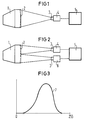
- 1 denotes a monitor.
- the image on the screen 2 is recorded by a camera 4 via optics 3.
- the values output by the camera are processed in an evaluation logic 5.
- Figure 2 differs from Figure 1 only in that several cameras 4, 6 are used in this structure.
- a special image is generated on the monitor to be adjusted.
- a dot structure similar to a fine checkerboard pattern was used.
- Other structures such as Use line structures.
- the purpose of this special image is to generate as many light-dark transitions on the screen as possible.
- the term “as many light-dark transitions as possible” is to be understood to mean that the finest structures are displayed on the screen, which can be displayed due to the technical design of the monitor to be adjusted.
- the monitor image is recorded with a semiconductor camera 4, 6.
- the image section and thus the resolution should be selected so that the fine dot structure in the camera signal is recorded at full resolution.
- the cameras used here with CCD semiconductor sensors have a certain number of photosensitive surface elements (pixels) on the sensor chip. Similar to the definition of the vertical and horizontal resolution of television pictures, the line resolution is given for each camera. This resolution depends not only on the number of pixels, but also on the bandwidth of the subsequent camera video amplifier. The resolution required here is achieved, for example, if the monitor dot structure is recorded with double resolution, based on the camera resolution.
- the camera signal is evaluated using a known image processing system.
- the image processing system is also used to determine image position, image height, image width, etc. using other test images on the screen.
- the sharpness of the gray image captured by the camera is now determined using the histogram, for example in a binary image system using the following method:
- the threshold value level n the number of pixels is formed (sum m), the voltage values of which lie in the gray image above the threshold value n.
- the threshold value is then increased by one value and the sum (m + 1) of the pixels is determined, the voltage values of which lie above the threshold value (n + 1). From the Difference (m + 1) and m results in the height of the bar to be displayed for the gray value n in the histogram. This calculation is carried out for the gray scale levels 0 to 255 ( Figure 3).
- the width of the histogram curve can be a measure of the sharpness of the image.
- the corresponding potentiometer on the deflection module of the monitor can be adjusted using a suitable device, for example.
- a suitable device for example, if an electric motor screwdriver is attached to a robot's gripper, the flexibility required for a specific purpose can be achieved.
- the different monitors differ not only in size, the potentiometers are also located in different positions on the respective deflection modules.
- the histogram can be calculated in a short time (a few hundred milliseconds). This achieves a short acquisition time for image sharpness, which is necessary for production automation.
- an average value of the image sharpness can be calculated for the entire monitor image.
- the line direction of the recording cameras must be 90 ° to the line direction of the monitor.
- a simple synchronization of the image acquisition can be realized.
Landscapes
- Engineering & Computer Science (AREA)
- Manufacturing & Machinery (AREA)
- Health & Medical Sciences (AREA)
- Biomedical Technology (AREA)
- General Health & Medical Sciences (AREA)
- Multimedia (AREA)
- Signal Processing (AREA)
- Testing, Inspecting, Measuring Of Stereoscopic Televisions And Televisions (AREA)
- Image Processing (AREA)
- Length Measuring Devices By Optical Means (AREA)
- Stereophonic System (AREA)
- Power Steering Mechanism (AREA)
- Grinding Of Cylindrical And Plane Surfaces (AREA)
- Controls And Circuits For Display Device (AREA)
- Video Image Reproduction Devices For Color Tv Systems (AREA)
- Control Of Combustion (AREA)
- Cleaning In Electrography (AREA)
- Automatic Focus Adjustment (AREA)
Claims (5)
- Procédé pour déterminer automatiquement la netteté de l'image dans des tubes images, notamment dans des moniteurs monochromes ou en couleurs, qui, au moyen d'un faisceau d'électrons, balayent l'écran (2) sous la forme de lignes parallèles, un potentiomètre permettant le réglage de la netteté étant présent dans le module de déviation du moniteur,
caractérisé par les étapes suivantes :- sur l'écran (2) d'un moniteur (1), une image particulière unique comportant un nombre optimum de transitions clairsombre, est formée sous la forme d'un damier fin ou d'un modèle de lignes,- l'image est enregistrée au moyen d'une caméra à semiconducteurs (4), l'échelle de grandissement lors de l'enregistrement de l'image détectant la structure de fond du moniteur dans le signal de la caméra, au moins avec une résolution double,- le signal délivré par la caméra est évalué au moyen d'une unité logique d'évaluation (5), pour ce qui concerne la netteté de l'image, dans les directions verticale et horizontale à l'aide d'un calcul d'histogramme, la largeur de la courbe d'histogramme déterminée sur la base d'échelons de valeurs de gris étant une mesure de la netteté de l'image, et le réglage de la netteté étant réalisé au moyen du potentiomètre situé dans le module de déviation du moniteur (1). - Procédé suivant la revendication 1, caractérisé par le fait qu'on utilise comme moyens de réglage un tournevis à moteur électrique actionné manuellement ou fixé sur l'élément de préhension d'un robot industriel.
- Procédé suivant la revendication 1, caractérisé par le fait que dans le cas de l'utilisation d'un réglage électronique de la netteté de l'image, la valeur de consigne de la netteté de l'image est introduite non pas au moyen d'un potentiomètre, mais par l'intermédiaire d'une interface électronique, dans le système électronique du moniteur.
- Procédé suivant l'une des revendications précédentes, caractérisé par le fait que pour déterminer une netteté d'image répartie uniformément sur l'écran, on enregistre une majeure partie de l'écran ou de l'ensemble de l'écran, en enregistrant, à l'aide de plusieurs caméras, des éléments de surface de l'écran et en utilisant, pour la détermination de la netteté de l'image, l'information d'image fournie par toutes les caméras.
- Procédé suivant l'une des revendications précédentes, caractérisé par le fait que la direction des lignes des caméras d'enregistrement (4,6) est décalée de 90° par rapport à la direction des lignes de moniteurs (1), pour l'obtention d'un enregistrement non perturbé de différents types de moniteurs, qui travaillent avec des fréquences d'images différentes, avec des caméras vidéo qui fonctionnent à des fréquences d'images de 50 Hz ou 60 Hz.
Priority Applications (1)
| Application Number | Priority Date | Filing Date | Title |
|---|---|---|---|
| AT89103420T ATE93110T1 (de) | 1988-03-22 | 1989-02-27 | Automatischer bildschaerfeabgleich von bildroehren. |
Applications Claiming Priority (2)
| Application Number | Priority Date | Filing Date | Title |
|---|---|---|---|
| DE3809602 | 1988-03-22 | ||
| DE3809602 | 1988-03-22 |
Publications (2)
| Publication Number | Publication Date |
|---|---|
| EP0342318A1 EP0342318A1 (fr) | 1989-11-23 |
| EP0342318B1 true EP0342318B1 (fr) | 1993-08-11 |
Family
ID=6350371
Family Applications (1)
| Application Number | Title | Priority Date | Filing Date |
|---|---|---|---|
| EP89103420A Expired - Lifetime EP0342318B1 (fr) | 1988-03-22 | 1989-02-27 | Ajustement automatique de la netteté pour tubes images |
Country Status (8)
| Country | Link |
|---|---|
| US (1) | US4955680A (fr) |
| EP (1) | EP0342318B1 (fr) |
| JP (1) | JPH028893A (fr) |
| AT (1) | ATE93110T1 (fr) |
| CA (1) | CA1331804C (fr) |
| DE (1) | DE58905217D1 (fr) |
| FI (1) | FI88095C (fr) |
| NO (1) | NO891218L (fr) |
Families Citing this family (8)
| Publication number | Priority date | Publication date | Assignee | Title |
|---|---|---|---|---|
| JPH01236869A (ja) * | 1988-03-17 | 1989-09-21 | Fuji Photo Film Co Ltd | カラースキャナの画像処理方法 |
| US5115229A (en) * | 1988-11-23 | 1992-05-19 | Hanoch Shalit | Method and system in video image reproduction |
| JP2899059B2 (ja) * | 1990-04-27 | 1999-06-02 | キヤノン株式会社 | 投写型テレビジョン装置 |
| JP2819956B2 (ja) * | 1992-08-31 | 1998-11-05 | 株式会社日立製作所 | Crt表示装置 |
| US6326996B1 (en) * | 1995-11-06 | 2001-12-04 | Gateway, Inc. | Display device having self contained diagnostic image generation capability |
| US6130756A (en) * | 1998-03-12 | 2000-10-10 | Eastman Kodak Co | Method for characterizing a response function of an output |
| AU2003272790A1 (en) | 2002-10-08 | 2004-05-04 | Honeywell International Inc. | Semiconductor packages, lead-containing solders and anodes and methods of removing alpha-emitters from materials |
| KR101733103B1 (ko) * | 2012-02-02 | 2017-05-08 | 아셀산 엘렉트로닉 사나이 베 티카렛 아노님 시르케티 | 전자 이미징 시스템을 포커싱하는 시스템 및 방법 |
Family Cites Families (16)
| Publication number | Priority date | Publication date | Assignee | Title |
|---|---|---|---|---|
| DE1203041B (de) * | 1963-08-29 | 1965-10-14 | Dipl Wirtsch Ing Dieter Schade | Futterdosierungs- und Futterverteilanlage fuer koerniges Trockenfutter, insbesondere fuer trockene Schrotfuetterung von Schweinen |
| US3450833A (en) * | 1966-01-14 | 1969-06-17 | Itek Corp | Automatic focusing system for a flying-spot scanner |
| US3962722A (en) * | 1974-11-27 | 1976-06-08 | Zenith Radio Corporation | Color television setup apparatus and method |
| JPS5911152B2 (ja) * | 1976-10-19 | 1984-03-13 | 肇産業株式会社 | パタ−ンマツチング方法及びその実施装置 |
| JPS5391521A (en) * | 1977-01-24 | 1978-08-11 | Hitachi Ltd | Detector for convergence chromatic aberration |
| US4163308A (en) * | 1977-06-24 | 1979-08-07 | Hitachi, Ltd. | Deflection yoke assembly positioning device |
| DE2805691C3 (de) * | 1978-02-10 | 1983-11-03 | Siemens AG, 1000 Berlin und 8000 München | Digitale Steuereinheit in einem Farbfernseh-Empfänger zur Ansteuerung der Ablenkendstufen |
| DE2839187C2 (de) * | 1978-09-08 | 1985-04-25 | Dr.-Ing. Rudolf Hell Gmbh, 2300 Kiel | Verfahren zur Ermittlung der Normfarbwerte von auf einem Farbmonitor dargestellten Farben |
| NL7903468A (nl) * | 1979-05-03 | 1980-11-05 | Philips Nv | Inrichting voor het meten en werkwijzen voor het meten en instellen van de convergentie van de elektronen- bundels in kleurenbeeldbuizen. |
| US4258298A (en) * | 1979-12-28 | 1981-03-24 | Sperry Corporation | Dynamic focus control and power supply for cathode ray tube displays |
| US4285004A (en) * | 1980-02-25 | 1981-08-18 | Ampex Corporation | Total raster error correction apparatus and method for the automatic set up of television cameras and the like |
| US4387394A (en) * | 1980-12-31 | 1983-06-07 | Rca Corporation | Sensing focus of a color kinescope |
| US4466014A (en) * | 1982-09-30 | 1984-08-14 | Allied Corporation | Video test method and apparatus with incremental scan rate capability |
| EP0119282B1 (fr) * | 1983-03-15 | 1986-06-18 | Deutsche ITT Industries GmbH | Récepteur de télévision avec système numérique d'ajustement automatique |
| GB8315183D0 (en) * | 1983-06-02 | 1983-07-06 | Gen Electric Co Plc | Colour crt display device |
| US4746985A (en) * | 1985-04-11 | 1988-05-24 | Rank Cintel Limited | Generating picture effects in video signals |
-
1989
- 1989-02-27 EP EP89103420A patent/EP0342318B1/fr not_active Expired - Lifetime
- 1989-02-27 DE DE8989103420T patent/DE58905217D1/de not_active Expired - Fee Related
- 1989-02-27 AT AT89103420T patent/ATE93110T1/de not_active IP Right Cessation
- 1989-03-06 US US07/318,830 patent/US4955680A/en not_active Expired - Fee Related
- 1989-03-20 CA CA000594171A patent/CA1331804C/fr not_active Expired - Fee Related
- 1989-03-20 NO NO89891218A patent/NO891218L/no unknown
- 1989-03-20 JP JP1070267A patent/JPH028893A/ja active Pending
- 1989-03-21 FI FI891349A patent/FI88095C/fi not_active IP Right Cessation
Also Published As
| Publication number | Publication date |
|---|---|
| FI88095C (fi) | 1993-03-25 |
| EP0342318A1 (fr) | 1989-11-23 |
| US4955680A (en) | 1990-09-11 |
| NO891218D0 (no) | 1989-03-20 |
| CA1331804C (fr) | 1994-08-30 |
| FI88095B (fi) | 1992-12-15 |
| JPH028893A (ja) | 1990-01-12 |
| FI891349A (fi) | 1989-09-23 |
| ATE93110T1 (de) | 1993-08-15 |
| NO891218L (no) | 1989-09-25 |
| DE58905217D1 (de) | 1993-09-16 |
| FI891349A0 (fi) | 1989-03-21 |
Similar Documents
| Publication | Publication Date | Title |
|---|---|---|
| DE69515646T2 (de) | Verfahren und Vorrichtung zum Erfassen von Fehlern in Textilbahnen und dergleichen | |
| DE69328154T2 (de) | Sensor-Vorrichtung und -Verfahren mit Unterdrückung von Nichtuniformitäten und gleichzeitiger Erhaltung von Bildinhalten | |
| EP0095517B1 (fr) | Procédure et dispositif pour une suspection optique automatique | |
| DE3639636C2 (de) | Automatische Inspektion von Textilbahnen | |
| DE3347645C1 (de) | Verfahren und Einrichtung zum opto-elektronischen Pruefen eines Flaechenmusters an einem Objekt | |
| DE10000364B4 (de) | Merkmalbasierende Feststellung von Fehlern | |
| EP0309758B1 (fr) | Procédé et dispositif pour constater et évaluer des fissures superficielles sur des pièces à usiner | |
| DE3612233C2 (fr) | ||
| DE69923119T2 (de) | Vorrichtung zur integrierten Verarbeitung von Defektabbildungen | |
| DE69427989T2 (de) | Verfahren und vorrichtung zur prüfung von leiterplatten mit verschiedenen vergrösserungen | |
| EP3417237B1 (fr) | Plaque de référence et procédé pour calibrer et/ou vérifier un système de détection par déflectométrie | |
| DE102006017337A1 (de) | Verfahren zur optischen Erfassung von bewegten Objekten und Vorrichtung | |
| DE102007025304B4 (de) | Verfahren zur Verbesserung der Reproduzierbarkeit einer Koordinaten-Messmaschine und deren Genauigkeit | |
| DE102016203392B3 (de) | Bildinspektionsverfahren mit mehreren Kameras | |
| DE2011470A1 (de) | Verfahren zum Auswerten eines nach einem Rasterverfahren aufgenommenen Bildes | |
| WO1989008836A1 (fr) | Procede et dispositif de detection de defauts dans des pieces embouties a la piece ou dans d'autres pieces a usiner | |
| EP0342318B1 (fr) | Ajustement automatique de la netteté pour tubes images | |
| DE69129908T2 (de) | Verfahren zur helligkeitsverbesserung | |
| DE2653590B2 (de) | Vorrichtung zum Ermitteln von Fehlern in flächenhaften Mustern, insbesondere in Photomasken | |
| DE2439988A1 (de) | Verfahren und vorrichtung zur ermittlung von oertlich begrenzten formfehlern an gewoelbten flaechen | |
| EP0992180B1 (fr) | Procede pour regler automatiquement l'intensite d'un eclairage destine a des unites servant a detecter une position et/ou a effectuer un controle de qualite | |
| DE19848243A1 (de) | Biegewinkelerfassungssystem | |
| EP0753231B1 (fr) | Procede et dispositif de binarisation des donnees de pixel | |
| DE2916159C2 (de) | Inspektionseinrichtung | |
| DE19815066B4 (de) | Filmabtaster mit Bildstandsfehlerkorrektur |
Legal Events
| Date | Code | Title | Description |
|---|---|---|---|
| PUAI | Public reference made under article 153(3) epc to a published international application that has entered the european phase |
Free format text: ORIGINAL CODE: 0009012 |
|
| AK | Designated contracting states |
Kind code of ref document: A1 Designated state(s): AT BE CH DE FR GB IT LI LU NL SE |
|
| 17P | Request for examination filed |
Effective date: 19891206 |
|
| 17Q | First examination report despatched |
Effective date: 19911216 |
|
| GRAA | (expected) grant |
Free format text: ORIGINAL CODE: 0009210 |
|
| AK | Designated contracting states |
Kind code of ref document: B1 Designated state(s): AT BE CH DE FR GB IT LI LU NL SE |
|
| PG25 | Lapsed in a contracting state [announced via postgrant information from national office to epo] |
Ref country code: SE Effective date: 19930811 Ref country code: BE Effective date: 19930811 |
|
| REF | Corresponds to: |
Ref document number: 93110 Country of ref document: AT Date of ref document: 19930815 Kind code of ref document: T |
|
| REF | Corresponds to: |
Ref document number: 58905217 Country of ref document: DE Date of ref document: 19930916 |
|
| ITF | It: translation for a ep patent filed | ||
| GBT | Gb: translation of ep patent filed (gb section 77(6)(a)/1977) |
Effective date: 19931021 |
|
| ET | Fr: translation filed | ||
| PG25 | Lapsed in a contracting state [announced via postgrant information from national office to epo] |
Ref country code: LU Free format text: LAPSE BECAUSE OF NON-PAYMENT OF DUE FEES Effective date: 19940228 Ref country code: LI Effective date: 19940228 Ref country code: CH Effective date: 19940228 |
|
| PLBE | No opposition filed within time limit |
Free format text: ORIGINAL CODE: 0009261 |
|
| STAA | Information on the status of an ep patent application or granted ep patent |
Free format text: STATUS: NO OPPOSITION FILED WITHIN TIME LIMIT |
|
| 26N | No opposition filed | ||
| REG | Reference to a national code |
Ref country code: CH Ref legal event code: PL |
|
| PGFP | Annual fee paid to national office [announced via postgrant information from national office to epo] |
Ref country code: GB Payment date: 19970123 Year of fee payment: 9 |
|
| PGFP | Annual fee paid to national office [announced via postgrant information from national office to epo] |
Ref country code: AT Payment date: 19970129 Year of fee payment: 9 |
|
| PGFP | Annual fee paid to national office [announced via postgrant information from national office to epo] |
Ref country code: NL Payment date: 19970225 Year of fee payment: 9 Ref country code: FR Payment date: 19970225 Year of fee payment: 9 |
|
| PGFP | Annual fee paid to national office [announced via postgrant information from national office to epo] |
Ref country code: DE Payment date: 19970418 Year of fee payment: 9 |
|
| PG25 | Lapsed in a contracting state [announced via postgrant information from national office to epo] |
Ref country code: GB Free format text: LAPSE BECAUSE OF NON-PAYMENT OF DUE FEES Effective date: 19980227 Ref country code: AT Free format text: LAPSE BECAUSE OF NON-PAYMENT OF DUE FEES Effective date: 19980227 |
|
| PG25 | Lapsed in a contracting state [announced via postgrant information from national office to epo] |
Ref country code: FR Free format text: THE PATENT HAS BEEN ANNULLED BY A DECISION OF A NATIONAL AUTHORITY Effective date: 19980228 |
|
| PG25 | Lapsed in a contracting state [announced via postgrant information from national office to epo] |
Ref country code: NL Free format text: LAPSE BECAUSE OF NON-PAYMENT OF DUE FEES Effective date: 19980901 |
|
| GBPC | Gb: european patent ceased through non-payment of renewal fee |
Effective date: 19980227 |
|
| NLV4 | Nl: lapsed or anulled due to non-payment of the annual fee |
Effective date: 19980901 |
|
| PG25 | Lapsed in a contracting state [announced via postgrant information from national office to epo] |
Ref country code: DE Free format text: LAPSE BECAUSE OF NON-PAYMENT OF DUE FEES Effective date: 19981103 |
|
| REG | Reference to a national code |
Ref country code: FR Ref legal event code: ST |
|
| PG25 | Lapsed in a contracting state [announced via postgrant information from national office to epo] |
Ref country code: IT Free format text: LAPSE BECAUSE OF NON-PAYMENT OF DUE FEES;WARNING: LAPSES OF ITALIAN PATENTS WITH EFFECTIVE DATE BEFORE 2007 MAY HAVE OCCURRED AT ANY TIME BEFORE 2007. THE CORRECT EFFECTIVE DATE MAY BE DIFFERENT FROM THE ONE RECORDED. Effective date: 20050227 |