EP0342318B1 - Automatic sharpness adjustment for picture tubes - Google Patents
Automatic sharpness adjustment for picture tubes Download PDFInfo
- Publication number
- EP0342318B1 EP0342318B1 EP89103420A EP89103420A EP0342318B1 EP 0342318 B1 EP0342318 B1 EP 0342318B1 EP 89103420 A EP89103420 A EP 89103420A EP 89103420 A EP89103420 A EP 89103420A EP 0342318 B1 EP0342318 B1 EP 0342318B1
- Authority
- EP
- European Patent Office
- Prior art keywords
- picture
- monitor
- focus
- image
- screen
- Prior art date
- Legal status (The legal status is an assumption and is not a legal conclusion. Google has not performed a legal analysis and makes no representation as to the accuracy of the status listed.)
- Expired - Lifetime
Links
- 239000004065 semiconductor Substances 0.000 claims abstract description 5
- 238000000034 method Methods 0.000 claims description 12
- 230000007704 transition Effects 0.000 claims description 3
- 238000003384 imaging method Methods 0.000 claims description 2
- 235000005121 Sorbus torminalis Nutrition 0.000 claims 1
- 244000152100 Sorbus torminalis Species 0.000 claims 1
- 238000010894 electron beam technology Methods 0.000 claims 1
- 238000012545 processing Methods 0.000 abstract description 6
- 238000004519 manufacturing process Methods 0.000 description 4
- 230000008859 change Effects 0.000 description 2
- 238000013461 design Methods 0.000 description 2
- 238000001514 detection method Methods 0.000 description 2
- 238000011161 development Methods 0.000 description 2
- 230000018109 developmental process Effects 0.000 description 2
- 238000005259 measurement Methods 0.000 description 2
- 230000008569 process Effects 0.000 description 2
- 230000006978 adaptation Effects 0.000 description 1
- 230000008901 benefit Effects 0.000 description 1
- 238000011156 evaluation Methods 0.000 description 1
- 230000001360 synchronised effect Effects 0.000 description 1
- 238000012360 testing method Methods 0.000 description 1
- 238000012549 training Methods 0.000 description 1
Images
Classifications
-
- H—ELECTRICITY
- H01—ELECTRIC ELEMENTS
- H01J—ELECTRIC DISCHARGE TUBES OR DISCHARGE LAMPS
- H01J9/00—Apparatus or processes specially adapted for the manufacture, installation, removal, maintenance of electric discharge tubes, discharge lamps, or parts thereof; Recovery of material from discharge tubes or lamps
- H01J9/44—Factory adjustment of completed discharge tubes or lamps to comply with desired tolerances
-
- H—ELECTRICITY
- H04—ELECTRIC COMMUNICATION TECHNIQUE
- H04N—PICTORIAL COMMUNICATION, e.g. TELEVISION
- H04N17/00—Diagnosis, testing or measuring for television systems or their details
- H04N17/04—Diagnosis, testing or measuring for television systems or their details for receivers
Definitions
- the invention relates to a method according to the preamble of claim 1.
- a method is known, for example, from the publication: Funkschau/2017 Anlagen-Shion, Volume 58, No. 5, February 1986, pp. 40-42; D. Beisse: geometry adjustment with camera and computer known.
- the automation of image matching should not only increase the cost-effectiveness of production, but also bring about quality improvements.
- Known sensor systems can be used, for example, to determine the image height, image width, image position and image brightness.
- an automatic determination of the image sharpness is difficult to implement or involves considerable effort.
- the recording camera is to be synchronized with the various monitors.
- the screen has been viewed with the eye in most cases.
- the employee can see the difference between the sharpness of the image on the edge and that in the middle.
- the sharpness of the image is adjusted by adjusting a potentiometer on the deflection module.
- measuring marks are recorded on a part of the monitor image using known methods, for example with a semiconductor camera.
- the camera signal is evaluated and the image sharpness is recorded.
- monitors with different frame rates are to be compared, the above-mentioned solution for 50 Hz monitors can only be used in principle.
- the measurement of the image sharpness of the entire image content and the expansion of the hardware circuit are carried out in such a way that a quick adaptation to the different image change frequencies is possible.
- the invention has for its object to design a method for automating the image matching of picture tubes, which can also be used when the picture is taken, for example different monitors or televisions should take place, which are compared, for example, with three different frame rates.
- the imaging scale should be selected so that the pixels of the monitor are recorded with twice the resolution in relation to the line resolution of the camera.
- the main advantage of the invention is that the image sharpness can be determined with appropriate image acquisition and image processing systems using appropriate programs, on monitors or television sets with different image change frequencies without extensive electronic hardware expenditure.
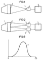
- 1 denotes a monitor.
- the image on the screen 2 is recorded by a camera 4 via optics 3.
- the values output by the camera are processed in an evaluation logic 5.
- Figure 2 differs from Figure 1 only in that several cameras 4, 6 are used in this structure.
- a special image is generated on the monitor to be adjusted.
- a dot structure similar to a fine checkerboard pattern was used.
- Other structures such as Use line structures.
- the purpose of this special image is to generate as many light-dark transitions on the screen as possible.
- the term “as many light-dark transitions as possible” is to be understood to mean that the finest structures are displayed on the screen, which can be displayed due to the technical design of the monitor to be adjusted.
- the monitor image is recorded with a semiconductor camera 4, 6.
- the image section and thus the resolution should be selected so that the fine dot structure in the camera signal is recorded at full resolution.
- the cameras used here with CCD semiconductor sensors have a certain number of photosensitive surface elements (pixels) on the sensor chip. Similar to the definition of the vertical and horizontal resolution of television pictures, the line resolution is given for each camera. This resolution depends not only on the number of pixels, but also on the bandwidth of the subsequent camera video amplifier. The resolution required here is achieved, for example, if the monitor dot structure is recorded with double resolution, based on the camera resolution.
- the camera signal is evaluated using a known image processing system.
- the image processing system is also used to determine image position, image height, image width, etc. using other test images on the screen.
- the sharpness of the gray image captured by the camera is now determined using the histogram, for example in a binary image system using the following method:
- the threshold value level n the number of pixels is formed (sum m), the voltage values of which lie in the gray image above the threshold value n.
- the threshold value is then increased by one value and the sum (m + 1) of the pixels is determined, the voltage values of which lie above the threshold value (n + 1). From the Difference (m + 1) and m results in the height of the bar to be displayed for the gray value n in the histogram. This calculation is carried out for the gray scale levels 0 to 255 ( Figure 3).
- the width of the histogram curve can be a measure of the sharpness of the image.
- the corresponding potentiometer on the deflection module of the monitor can be adjusted using a suitable device, for example.
- a suitable device for example, if an electric motor screwdriver is attached to a robot's gripper, the flexibility required for a specific purpose can be achieved.
- the different monitors differ not only in size, the potentiometers are also located in different positions on the respective deflection modules.
- the histogram can be calculated in a short time (a few hundred milliseconds). This achieves a short acquisition time for image sharpness, which is necessary for production automation.
- an average value of the image sharpness can be calculated for the entire monitor image.
- the line direction of the recording cameras must be 90 ° to the line direction of the monitor.
- a simple synchronization of the image acquisition can be realized.
Landscapes
- Engineering & Computer Science (AREA)
- Manufacturing & Machinery (AREA)
- Health & Medical Sciences (AREA)
- Biomedical Technology (AREA)
- General Health & Medical Sciences (AREA)
- Multimedia (AREA)
- Signal Processing (AREA)
- Testing, Inspecting, Measuring Of Stereoscopic Televisions And Televisions (AREA)
- Image Processing (AREA)
- Length Measuring Devices By Optical Means (AREA)
- Stereophonic System (AREA)
- Video Image Reproduction Devices For Color Tv Systems (AREA)
- Control Of Combustion (AREA)
- Cleaning In Electrography (AREA)
- Power Steering Mechanism (AREA)
- Grinding Of Cylindrical And Plane Surfaces (AREA)
- Controls And Circuits For Display Device (AREA)
- Automatic Focus Adjustment (AREA)
Abstract
Description
Die Erfindung betrifft ein Verfahren nach dem Oberbegriff des Anspruchs 1. Ein solches Verfahren ist beispielsweise aus der Druckschrift : Funkschau Fernsehgeräte-Produktion , Band 58, Nr. 5, Februar 1986, S.40- 42; D. Beisse : Geometrieabgleich mit Kamera und Computer bekannt.The invention relates to a method according to the preamble of claim 1. Such a method is known, for example, from the publication: Funkschau Fernsehgeräte-Produktion, Volume 58, No. 5, February 1986, pp. 40-42; D. Beisse: geometry adjustment with camera and computer known.
In vielen Prozeßabläufen werden auf Fernsehmonitoren Bilder, Schriften und Graphiken dargestellt. Hierzu wird eine optimale Bildschärfe benötigt. Da die Bildschärfe an verschiedenen Stellen des Bildschirms unterschiedlich sein kann, muß der gesamte Bildinhalt zur Beurteilung der Bildschärfe herangezogen werden.In many processes, images, fonts and graphics are displayed on television monitors. This requires an optimal image sharpness. Since the sharpness of the image can differ at different points on the screen, the entire image content must be used to assess the sharpness of the image.
Bisher konnte dieser Vorgang nur mit einem sehr hohen apparativen Aufwand automatisiert werden.Until now, this process could only be automated with a very high level of equipment.
Bei der Fertigung von Monitoren und Fernsehgeräten müssen nicht nur elektrische Werte geprüft und eingestellt werden, sondern es müssen auch die Bildgeometrie und andere Bildparameter eingestellt werden.When manufacturing monitors and televisions, not only must electrical values be checked and set, but also the image geometry and other image parameters must be set.
Die Automatisierung des Bildabgleichs soll nicht nur die Wirtschaftlichkeit der Fertigung erhöhen, sondern auch Qualitätsverbesserungen erbringen.The automation of image matching should not only increase the cost-effectiveness of production, but also bring about quality improvements.
Die Ermittlung von zum Beispiel Bildhöhe, Bildbreite, Bildlage und Bildhelligkeit kann mit bekannten Sensorsystemen durchgeführt werden. Dagegen ist eine automatische Ermittlung der Bildschärfe nur schwer realisierbar oder mit erheblichem Aufwand verbunden.Known sensor systems can be used, for example, to determine the image height, image width, image position and image brightness. In contrast, an automatic determination of the image sharpness is difficult to implement or involves considerable effort.
Ein weiteres Problem ergibt sich, wenn die Bildaufnahme an verschiedenen Monitoren oder Fernsehgeräten erfolgen soll. Es gibt Fernsehgeräte, die entweder mit 50 Hz oder 60 Hz-Halbbild-Wechselfrequenz arbeiten. In einer Monitor-Montagelinie sollen beispielsweise Monitore mit drei verschiedenen Bildwechselfrequenzen abgeglichen werden. Für die hier benötigte, automatischeAnother problem arises when the image is to be recorded on different monitors or television sets. There are televisions that work with either 50 Hz or 60 Hz field alternating frequency. In a monitor assembly line, for example, monitors with three different frame rates are to be compared. For the automatic one needed here
Bildaufnahme ist die aufnehmende Kamera mit den verschiedenen Monitoren zu synchronisieren.The recording camera is to be synchronized with the various monitors.
Bisher wurde in den meisten Fällen der Bildschirm mit dem Auge betrachtet. Bei ausreichender Einarbeitung kann der Mitarbeiter am Bildschirm den Unterschied zwischen der Bildschärfe am Rand und der in der Mitte erkennen. Die Einstellung der Bildschärfe erfolgt durch Justierung eines Potentiometers an der Ablenkbaugruppe.So far, the screen has been viewed with the eye in most cases. With sufficient training, the employee can see the difference between the sharpness of the image on the edge and that in the middle. The sharpness of the image is adjusted by adjusting a potentiometer on the deflection module.
Bei einer automatischen Erfassung der Bildschärfe werden nach bekannten Verfahren zum Beispiel mit einer Halbleiterkamera Meßmarken auf einem Teil des Monitorbildes aufgenommen. Mit einer speziellen, aufwendigen Hardware-Logik wird das Kamerasignal ausgewertet und die Bildschärfe erfaßt.In the case of automatic detection of the image sharpness, measuring marks are recorded on a part of the monitor image using known methods, for example with a semiconductor camera. With special, complex hardware logic, the camera signal is evaluated and the image sharpness is recorded.
Wenn Monitore mit verschiedenen Bildwechselfrequenzen abgeglichen werden sollen, kann die erwähnte Lösung für 50 Hz-Monitore nur prinzipiell eingesetzt werden. Mit einer Weiterentwicklung müßte
die Messung der Bildschärfe des gesamten Bildinhalts und die Erweiterung der Hardwareschaltung derart erfolgen, daß eine schnelle Anpassung an die verschiedenen Bildwechselfrequenzen möglich ist.If monitors with different frame rates are to be compared, the above-mentioned solution for 50 Hz monitors can only be used in principle. With a further development
the measurement of the image sharpness of the entire image content and the expansion of the hardware circuit are carried out in such a way that a quick adaptation to the different image change frequencies is possible.
Es ist auch bekannt, mit einem aufwendigen Bildverarbeitungssystem die Bildschärfe über die Gradienten-Verteilung im Graubild zu erfassen. Neben den hohen Hardware- und Softwarekosten besteht hier wie auch bei dem obengenannten Lösungsweg der Nachteil, daß mit vielen Messungen an verschiedenen Bildschirmstellen ein Bildschärfe-Mittelwert ermittelt werden muß. Damit wird die Dauer der Bildschärfe-Erfassung meist zu lang. Bei der Fertigungsautomatisierung sind Zeiten von einigen 100 Millisekunden anzustreben.It is also known to use a complex image processing system to detect the sharpness of the image via the gradient distribution in the gray image. In addition to the high hardware and software costs, as with the above-mentioned solution, there is the disadvantage that an image sharpness average must be determined with many measurements at different screen locations. The duration of the image sharpness detection is usually too long. In manufacturing automation, times of a few 100 milliseconds are desirable.
Der Erfindung liegt die Aufgabe zugrunde, ein Verfahren zur Automatisierung des Bildabgleichs von Bildröhren zu konzipieren, das auch einsetzbar ist, wenn die Bildaufnahme zum Beispiel an verschiedenen Monitoren oder Fernsehgeräten erfolgen soll, die zum Beispiel mit drei verschiedenen Bildwechselfrequenzen abgeglichen werden.The invention has for its object to design a method for automating the image matching of picture tubes, which can also be used when the picture is taken, for example different monitors or televisions should take place, which are compared, for example, with three different frame rates.
Die der Erfindung zugrundeliegende Aufgabe wird durch das Merkmal des kennzeichnenden Teils des Anspruchs 1 gelöst. Vorteilhafte Ausführungsformen und Weiterbildungen der Erfindung sind in den Unteransprüchen angegeben.The object on which the invention is based is achieved by the feature of the characterizing part of claim 1. Advantageous embodiments and developments of the invention are specified in the subclaims.
Der Abbildungsmaßstab ist so zu wählen, daß die Bildpunkte des Monitors mit zweifacher Auflösung bezogen auf die Linienauflösung der Kamera aufgenommen werden.The imaging scale should be selected so that the pixels of the monitor are recorded with twice the resolution in relation to the line resolution of the camera.
Der wesentliche Vorteil der Erfindung besteht darin, daß die Bildschärfe ohne umfangreichen Elektronik-Hardware-Aufwand mit heute üblichen Bildaufnahme- und Bildverarbeitungssystemen durch entsprechende Programme, an Monitoren oder Fernsehgeräten mit unterschiedlichen Bildwechselfrequenzen ermittelt werden kann.The main advantage of the invention is that the image sharpness can be determined with appropriate image acquisition and image processing systems using appropriate programs, on monitors or television sets with different image change frequencies without extensive electronic hardware expenditure.
Die Erfindung wird anhand der Figuren erläutert. Es zeigen
- Figur 1
- ein Prinzipbild,
- Figur 2
- diesen schematischen Aufbau mit mehreren Kameras und
- Figur 3
- eine Histogrammkurve.
- Figure 1
- a principle picture
- Figure 2
- this schematic structure with several cameras and
- Figure 3
- a histogram curve.
In der Figur 1 ist mit 1 ein Monitor bezeichnet. Das Bild auf dem Bildschirm 2 wird über eine Optik 3 von einer Kamera 4 aufgenommen. Die von der Kamera abgegebenen Werte werden in einer Auswertelogik 5 verarbeitet.In Figure 1, 1 denotes a monitor. The image on the screen 2 is recorded by a camera 4 via optics 3. The values output by the camera are processed in an evaluation logic 5.
Die Figur 2 unterschiedet sich nur insofern von der Figur 1, daß bei diesem Aufbau mehrere Kameras 4, 6 verwendet werden.Figure 2 differs from Figure 1 only in that several cameras 4, 6 are used in this structure.
In der Figur 3 sind auf der x-Achse die Grauwerte des Bildes und auf der y-Achse die Anzahl der Bildpunkte aufgetragen. Die Histogrammkurve ist mit 7 bezeichnet.3 shows the gray values of the image on the x-axis and the number of pixels on the y-axis. The histogram curve is labeled 7.
Auf dem abzugleichenden Monitor wird ein spezielles Bild erzeugt. Hier wurde eine Punktestruktur ähnlich einem feinen Schachbrettmuster verwendet. Es lassen sich auch andere Strukturen wie z.B. Linienstrukturen verwenden. Zweck dieses speziellen Bildes ist es, möglichst viele Hell-Dunkel-Übergänge am Bildschirm zu erzeugen. Unter dem Begriff "möglichst viele Hell-Dunkel-Übergänge" ist zu verstehen, daß am Bildschirm feinste Strukturen dargestellt werden, die aufgrund der technischen Ausführung des abzugleichenden Monitors abbildbar sind.A special image is generated on the monitor to be adjusted. Here a dot structure similar to a fine checkerboard pattern was used. Other structures such as Use line structures. The purpose of this special image is to generate as many light-dark transitions on the screen as possible. The term “as many light-dark transitions as possible” is to be understood to mean that the finest structures are displayed on the screen, which can be displayed due to the technical design of the monitor to be adjusted.
Das Monitorbild wird mit einer Halbleiterkamera 4, 6 aufgenommen. Der Bildausschnitt und damit die Auflösung ist so zu wählen, daß die feine Punktestruktur im Kamerasignal mit voller Auflösung erfaßt wird. Die hier verwendeten Kameras mit CCD-Halbleiter-Sensoren haben auf dem Sensor-Chip eine bestimmte Anzahl von photoempfindlichen Flächenelementen (Pixel). Ähnlich der Definition der vertikalen und horizontalen Auflösung von Fernsehbildern wird zu jeder Kamera die Linienauflösung angegeben. Diese Auflösung hängt nicht nur von der Pixelanzahl ab, sondern auch von der Bandbreite des nachfolgenden Kamera-Videoverstärkers. Die hier benötigte Auflösung wird zum Beispiel dann erreicht, wenn die Monitor-Punktestruktur mit doppelter Auflösung, bezogen auf die Kamera-Auflösung, aufgenommen wird.The monitor image is recorded with a semiconductor camera 4, 6. The image section and thus the resolution should be selected so that the fine dot structure in the camera signal is recorded at full resolution. The cameras used here with CCD semiconductor sensors have a certain number of photosensitive surface elements (pixels) on the sensor chip. Similar to the definition of the vertical and horizontal resolution of television pictures, the line resolution is given for each camera. This resolution depends not only on the number of pixels, but also on the bandwidth of the subsequent camera video amplifier. The resolution required here is achieved, for example, if the monitor dot structure is recorded with double resolution, based on the camera resolution.
Das Kamerasignal wird mit einem bekannten Bildverarbeitungssystem ausgewertet. Das Bildverarbeitungssystem wird auch dafür verwendet, um mit Hilfe anderer Testbilder am Bildschirm Bildlage, Bildhöhe, Bildbreite usw. zu ermitteln.The camera signal is evaluated using a known image processing system. The image processing system is also used to determine image position, image height, image width, etc. using other test images on the screen.
Die Bildschärfe des von der Kamera aufgenommenen Graubildes wird nun mit Hilfe des Histogramms ermittelt, zum Beispiel in einem Binärbildsystem nach folgender Methode:The sharpness of the gray image captured by the camera is now determined using the histogram, for example in a binary image system using the following method:
Bei der Schwellwertstufe n wird die Anzahl der Bildpunkte gebildet (Summe m), deren Spannungswerte im Graubild über dem Schwellwert n liegen. Anschließend wird der Schwellwert um einen Wert erhöht und die Summe (m + 1) der Bildpunkte ermittelt, deren Spannungswerte über dem Schwellwert (n + 1) liegen. Aus der Differenz (m + 1) und m ergibt sich die Höhe des darzustellenden Balkens für den Grauwert n im Histogramm. Diese Berechnung wird für die Grauwertstufen 0 bis 255 durchgeführt (Figur 3). Die Breite der Histogrammkurve kann ein Maß für die Bildschärfe sein.At the threshold value level n, the number of pixels is formed (sum m), the voltage values of which lie in the gray image above the threshold value n. The threshold value is then increased by one value and the sum (m + 1) of the pixels is determined, the voltage values of which lie above the threshold value (n + 1). From the Difference (m + 1) and m results in the height of the bar to be displayed for the gray value n in the histogram. This calculation is carried out for the gray scale levels 0 to 255 (Figure 3). The width of the histogram curve can be a measure of the sharpness of the image.
Bei unscharfem Bild kann zum Beispiel mit einer passenden Vorrichtung das zugehörige Potentiometer an der Ablenkbaugruppe des Monitors verstellt werden. Wenn zum Beispiel ein elektromotorischer Schrauber am Greifer eines Roboters befestigt wird, kann die für einen bestimmten Zweck benötigte Flexibilität erreicht werden. Die verschiedenen Monitore unterscheiden sich nicht nur durch die Größe, auch die Potentiometer befinden sich auf der jeweiligen Ablenkbaugruppe an unterschiedlicher Position.If the image is out of focus, the corresponding potentiometer on the deflection module of the monitor can be adjusted using a suitable device, for example. For example, if an electric motor screwdriver is attached to a robot's gripper, the flexibility required for a specific purpose can be achieved. The different monitors differ not only in size, the potentiometers are also located in different positions on the respective deflection modules.
Wenn das gesamte von der Kamera aufgenommene Graubild im Bildverarbeitungssystem abgespeichert wird, kann die Histogrammberechnung in kurzer Zeit erfolgen (einige hundert Millisekunden). Damit wird eine für die Fertigungsautomatisierung notwendige kurze Erfassungszeit der Bildschärfe erreicht.If the entire gray image recorded by the camera is stored in the image processing system, the histogram can be calculated in a short time (a few hundred milliseconds). This achieves a short acquisition time for image sharpness, which is necessary for production automation.
Durch Aufnahme des Bildschirms mit mehreren Kameras bei der oben erwähnten Vergrößerung bzw. Auflösung und der jeweiligen Histogrammberechnung kann ein Mittelwert der Bildschärfe für das gesamte Monitor-Bild berechnet werden.By recording the screen with several cameras at the above-mentioned magnification or resolution and the respective histogram calculation, an average value of the image sharpness can be calculated for the entire monitor image.
Um eine störungsfreie Bildaufnahme von verschiedenen Monitor- oder Fernsehgerätetypen, die mit unterschiedlichen Bildwechselfrequenzen arbeiten, mit kostengünstigen, handelsüblichen Videokameras, die normalerweise mit 50 Hz oder 60 Hz Bildwechselfrequenz (Halbbild) betrieben werden, zur erreichen, muß die Zeilenrichtung der aufnehmenden Kameras um 90° zu der Zeilenrichtung des Monitors angeordnet werden. Außerdem ist eine einfache Synchronisierung der Bildaufnahme zu realisieren.In order to achieve interference-free image recording of different types of monitors or televisions that work with different frame rates, with inexpensive, commercially available video cameras, which are normally operated with 50 Hz or 60 Hz frame rate, the line direction of the recording cameras must be 90 ° to the line direction of the monitor. In addition, a simple synchronization of the image acquisition can be realized.
Claims (5)
- Method for automatically determining the picture focus on picture tubes, preferably on monochrome or colour monitors which scan the screen (2) in the form of parallel lines by means of an electron beam, a potentiometer for focus adjustment being provided at the deflection assembly of the monitor, characterised by the following steps:- a single special picture with an optimum number of light/dark transitions in the form of a fine chequer board pattern or of a line pattern is generated on the screen (2) of a monitor (1),- the picture is picked up by means of a semiconductor camera (4), the imaging scale during the recording of the picture covering the dot structure of the monitor in the camera signal at least with twice the resolution,- the camera signal produced is analysed by means of a histogram calculation with respect to the image focus in vertical and horizontal direction by means of an analysing logic (5), the width of the histogram curve determined on the basis of grey scale steps being a measure of the picture focus and the focus being adjusted via the potentiometer at the deflection assembly of the monitor (1).
- Method according to Claim 1, characterised in that a screwdriver driven by an electric motor is used manually, or mounted on the gripper of an industrial robot, as adjusting means.
- Method according to Claim 1, characterised in that when instead of a potentiometer, an electronic picture focus adjustment is used, the nominal value of the picture focus is input into the electronics of the monitor via an electronic interface.
- Method according to one of the preceding claims, characterised in that, in order to determine a picture focus uniformly distributed over the screen, a large proportion of the screen or the total screen is recorded in that area elements of the screen are recorded by means of several cameras and the picture information of all cameras is used for determining the picture focus.
- Method according to one of the preceding claims, characterised in that the direction of the lines of the pick-up cameras (4, 6) is arranged at 90° with respect to the direction of the lines of the monitor (1) in order to achieve interference-free picture recording from different monitor types which operate with different frame rates, by means of video cameras which are operated at a frame rate of 50 Hz or 60 Hz.
Priority Applications (1)
| Application Number | Priority Date | Filing Date | Title |
|---|---|---|---|
| AT89103420T ATE93110T1 (en) | 1988-03-22 | 1989-02-27 | AUTOMATIC SHARPNESS ADJUSTMENT OF PICTURE TUBES. |
Applications Claiming Priority (2)
| Application Number | Priority Date | Filing Date | Title |
|---|---|---|---|
| DE3809602 | 1988-03-22 | ||
| DE3809602 | 1988-03-22 |
Publications (2)
| Publication Number | Publication Date |
|---|---|
| EP0342318A1 EP0342318A1 (en) | 1989-11-23 |
| EP0342318B1 true EP0342318B1 (en) | 1993-08-11 |
Family
ID=6350371
Family Applications (1)
| Application Number | Title | Priority Date | Filing Date |
|---|---|---|---|
| EP89103420A Expired - Lifetime EP0342318B1 (en) | 1988-03-22 | 1989-02-27 | Automatic sharpness adjustment for picture tubes |
Country Status (8)
| Country | Link |
|---|---|
| US (1) | US4955680A (en) |
| EP (1) | EP0342318B1 (en) |
| JP (1) | JPH028893A (en) |
| AT (1) | ATE93110T1 (en) |
| CA (1) | CA1331804C (en) |
| DE (1) | DE58905217D1 (en) |
| FI (1) | FI88095C (en) |
| NO (1) | NO891218L (en) |
Families Citing this family (8)
| Publication number | Priority date | Publication date | Assignee | Title |
|---|---|---|---|---|
| JPH01236869A (en) * | 1988-03-17 | 1989-09-21 | Fuji Photo Film Co Ltd | Image processing method for color scanner |
| US5115229A (en) * | 1988-11-23 | 1992-05-19 | Hanoch Shalit | Method and system in video image reproduction |
| JP2899059B2 (en) * | 1990-04-27 | 1999-06-02 | キヤノン株式会社 | Projection television device |
| JP2819956B2 (en) * | 1992-08-31 | 1998-11-05 | 株式会社日立製作所 | CRT display device |
| US6326996B1 (en) * | 1995-11-06 | 2001-12-04 | Gateway, Inc. | Display device having self contained diagnostic image generation capability |
| US6130756A (en) * | 1998-03-12 | 2000-10-10 | Eastman Kodak Co | Method for characterizing a response function of an output |
| AU2003272790A1 (en) | 2002-10-08 | 2004-05-04 | Honeywell International Inc. | Semiconductor packages, lead-containing solders and anodes and methods of removing alpha-emitters from materials |
| JP5883141B2 (en) * | 2012-02-02 | 2016-03-09 | アセルサン・エレクトロニク・サナイ・ヴェ・ティジャレット・アノニム・シルケティAselsan Elektronik Sanayi veTicaret Anonim Sirketi | System and method for focusing an electronic imaging system |
Family Cites Families (16)
| Publication number | Priority date | Publication date | Assignee | Title |
|---|---|---|---|---|
| DE1203041B (en) * | 1963-08-29 | 1965-10-14 | Dipl Wirtsch Ing Dieter Schade | Feed dosing and distribution system for grainy dry feed, especially for dry meal feeding of pigs |
| US3450833A (en) * | 1966-01-14 | 1969-06-17 | Itek Corp | Automatic focusing system for a flying-spot scanner |
| US3962722A (en) * | 1974-11-27 | 1976-06-08 | Zenith Radio Corporation | Color television setup apparatus and method |
| JPS5911152B2 (en) * | 1976-10-19 | 1984-03-13 | 肇産業株式会社 | Pattern matching method and its implementation device |
| JPS5391521A (en) * | 1977-01-24 | 1978-08-11 | Hitachi Ltd | Detector for convergence chromatic aberration |
| US4163308A (en) * | 1977-06-24 | 1979-08-07 | Hitachi, Ltd. | Deflection yoke assembly positioning device |
| DE2805691C3 (en) * | 1978-02-10 | 1983-11-03 | Siemens AG, 1000 Berlin und 8000 München | Digital control unit in a color television receiver to control the deflection output stages |
| DE2839187C2 (en) * | 1978-09-08 | 1985-04-25 | Dr.-Ing. Rudolf Hell Gmbh, 2300 Kiel | Process for determining the standard color values of colors displayed on a color monitor |
| NL7903468A (en) * | 1979-05-03 | 1980-11-05 | Philips Nv | MEASURING DEVICE AND METHODS FOR MEASURING AND ADJUSTING THE CONVERGENCE OF THE ELECTRON BEAMS IN COLOR IMAGE TUBES. |
| US4258298A (en) * | 1979-12-28 | 1981-03-24 | Sperry Corporation | Dynamic focus control and power supply for cathode ray tube displays |
| US4285004A (en) * | 1980-02-25 | 1981-08-18 | Ampex Corporation | Total raster error correction apparatus and method for the automatic set up of television cameras and the like |
| US4387394A (en) * | 1980-12-31 | 1983-06-07 | Rca Corporation | Sensing focus of a color kinescope |
| US4466014A (en) * | 1982-09-30 | 1984-08-14 | Allied Corporation | Video test method and apparatus with incremental scan rate capability |
| EP0119282B1 (en) * | 1983-03-15 | 1986-06-18 | Deutsche ITT Industries GmbH | Television receiver with an automatic digital adjustment system |
| GB8315183D0 (en) * | 1983-06-02 | 1983-07-06 | Gen Electric Co Plc | Colour crt display device |
| US4746985A (en) * | 1985-04-11 | 1988-05-24 | Rank Cintel Limited | Generating picture effects in video signals |
-
1989
- 1989-02-27 AT AT89103420T patent/ATE93110T1/en not_active IP Right Cessation
- 1989-02-27 DE DE8989103420T patent/DE58905217D1/en not_active Expired - Fee Related
- 1989-02-27 EP EP89103420A patent/EP0342318B1/en not_active Expired - Lifetime
- 1989-03-06 US US07/318,830 patent/US4955680A/en not_active Expired - Fee Related
- 1989-03-20 CA CA000594171A patent/CA1331804C/en not_active Expired - Fee Related
- 1989-03-20 NO NO89891218A patent/NO891218L/en unknown
- 1989-03-20 JP JP1070267A patent/JPH028893A/en active Pending
- 1989-03-21 FI FI891349A patent/FI88095C/en not_active IP Right Cessation
Also Published As
| Publication number | Publication date |
|---|---|
| US4955680A (en) | 1990-09-11 |
| FI88095C (en) | 1993-03-25 |
| FI88095B (en) | 1992-12-15 |
| ATE93110T1 (en) | 1993-08-15 |
| JPH028893A (en) | 1990-01-12 |
| NO891218L (en) | 1989-09-25 |
| NO891218D0 (en) | 1989-03-20 |
| FI891349A0 (en) | 1989-03-21 |
| DE58905217D1 (en) | 1993-09-16 |
| CA1331804C (en) | 1994-08-30 |
| FI891349L (en) | 1989-09-23 |
| EP0342318A1 (en) | 1989-11-23 |
Similar Documents
| Publication | Publication Date | Title |
|---|---|---|
| DE69515646T2 (en) | Method and device for detecting defects in textile webs and the like | |
| DE69328154T2 (en) | Sensor device and method with suppression of non-uniformities and simultaneous preservation of image content | |
| EP0095517B1 (en) | Process and device for an automatic optical inspection | |
| DE3639636C2 (en) | Automatic inspection of textile webs | |
| DE3347645C1 (en) | Method and device for opto-electronic testing of a surface pattern on an object | |
| EP0309758B1 (en) | Procedure and facility for determination and evaluation of surface cracks on workpieces | |
| DE10000364B4 (en) | Feature-based detection of errors | |
| DE3612233C2 (en) | ||
| DE69923119T2 (en) | Device for the integrated processing of defect images | |
| DE69427989T2 (en) | METHOD AND DEVICE FOR TESTING CIRCUIT BOARDS WITH VARIOUS ENLARGEMENTS | |
| DE3879015T2 (en) | METHOD AND DEVICE FOR SURVEYING PUNCH MASKS. | |
| DE112022005406B4 (en) | AI-based product surface inspection device and method | |
| DE102016203392B3 (en) | Image inspection method with multiple cameras | |
| DE102007025304B4 (en) | Method for improving the reproducibility of a coordinate measuring machine and its accuracy | |
| DE2011470A1 (en) | Method for evaluating an image recorded using a raster method | |
| WO2018077356A1 (en) | Reference plate and method for calibrating and/or checking a deflectometry sensor system | |
| EP0342318B1 (en) | Automatic sharpness adjustment for picture tubes | |
| DE3809221A1 (en) | METHOD FOR DETECTING DEFECTS IN PRESSING PARTS OR OTHER WORKPIECES, AND DEVICE FOR IMPLEMENTING THE METHOD | |
| DE69129908T2 (en) | METHOD FOR IMPROVING BRIGHTNESS | |
| DE19637234C2 (en) | Procedure for checking the color purity of surfaces | |
| DE2653590B2 (en) | Device for determining defects in two-dimensional patterns, in particular in photo masks | |
| DE2439988A1 (en) | Automatic fault detection on smooth curved surfaces - using laser scanning technique and suited to coachwork testing | |
| DE102006017337A1 (en) | Method for optically detecting moving objects and apparatus | |
| EP0992180B1 (en) | Method for automatically controlling the intensity of a lighting used in units for detecting a position and/or for quality control | |
| DE19848243A1 (en) | Bending angle detector for workpieces such as metal plate |
Legal Events
| Date | Code | Title | Description |
|---|---|---|---|
| PUAI | Public reference made under article 153(3) epc to a published international application that has entered the european phase |
Free format text: ORIGINAL CODE: 0009012 |
|
| AK | Designated contracting states |
Kind code of ref document: A1 Designated state(s): AT BE CH DE FR GB IT LI LU NL SE |
|
| 17P | Request for examination filed |
Effective date: 19891206 |
|
| 17Q | First examination report despatched |
Effective date: 19911216 |
|
| GRAA | (expected) grant |
Free format text: ORIGINAL CODE: 0009210 |
|
| AK | Designated contracting states |
Kind code of ref document: B1 Designated state(s): AT BE CH DE FR GB IT LI LU NL SE |
|
| PG25 | Lapsed in a contracting state [announced via postgrant information from national office to epo] |
Ref country code: SE Effective date: 19930811 Ref country code: BE Effective date: 19930811 |
|
| REF | Corresponds to: |
Ref document number: 93110 Country of ref document: AT Date of ref document: 19930815 Kind code of ref document: T |
|
| REF | Corresponds to: |
Ref document number: 58905217 Country of ref document: DE Date of ref document: 19930916 |
|
| ITF | It: translation for a ep patent filed | ||
| GBT | Gb: translation of ep patent filed (gb section 77(6)(a)/1977) |
Effective date: 19931021 |
|
| ET | Fr: translation filed | ||
| PG25 | Lapsed in a contracting state [announced via postgrant information from national office to epo] |
Ref country code: LU Free format text: LAPSE BECAUSE OF NON-PAYMENT OF DUE FEES Effective date: 19940228 Ref country code: LI Effective date: 19940228 Ref country code: CH Effective date: 19940228 |
|
| PLBE | No opposition filed within time limit |
Free format text: ORIGINAL CODE: 0009261 |
|
| STAA | Information on the status of an ep patent application or granted ep patent |
Free format text: STATUS: NO OPPOSITION FILED WITHIN TIME LIMIT |
|
| 26N | No opposition filed | ||
| REG | Reference to a national code |
Ref country code: CH Ref legal event code: PL |
|
| PGFP | Annual fee paid to national office [announced via postgrant information from national office to epo] |
Ref country code: GB Payment date: 19970123 Year of fee payment: 9 |
|
| PGFP | Annual fee paid to national office [announced via postgrant information from national office to epo] |
Ref country code: AT Payment date: 19970129 Year of fee payment: 9 |
|
| PGFP | Annual fee paid to national office [announced via postgrant information from national office to epo] |
Ref country code: NL Payment date: 19970225 Year of fee payment: 9 Ref country code: FR Payment date: 19970225 Year of fee payment: 9 |
|
| PGFP | Annual fee paid to national office [announced via postgrant information from national office to epo] |
Ref country code: DE Payment date: 19970418 Year of fee payment: 9 |
|
| PG25 | Lapsed in a contracting state [announced via postgrant information from national office to epo] |
Ref country code: GB Free format text: LAPSE BECAUSE OF NON-PAYMENT OF DUE FEES Effective date: 19980227 Ref country code: AT Free format text: LAPSE BECAUSE OF NON-PAYMENT OF DUE FEES Effective date: 19980227 |
|
| PG25 | Lapsed in a contracting state [announced via postgrant information from national office to epo] |
Ref country code: FR Free format text: THE PATENT HAS BEEN ANNULLED BY A DECISION OF A NATIONAL AUTHORITY Effective date: 19980228 |
|
| PG25 | Lapsed in a contracting state [announced via postgrant information from national office to epo] |
Ref country code: NL Free format text: LAPSE BECAUSE OF NON-PAYMENT OF DUE FEES Effective date: 19980901 |
|
| GBPC | Gb: european patent ceased through non-payment of renewal fee |
Effective date: 19980227 |
|
| NLV4 | Nl: lapsed or anulled due to non-payment of the annual fee |
Effective date: 19980901 |
|
| PG25 | Lapsed in a contracting state [announced via postgrant information from national office to epo] |
Ref country code: DE Free format text: LAPSE BECAUSE OF NON-PAYMENT OF DUE FEES Effective date: 19981103 |
|
| REG | Reference to a national code |
Ref country code: FR Ref legal event code: ST |
|
| PG25 | Lapsed in a contracting state [announced via postgrant information from national office to epo] |
Ref country code: IT Free format text: LAPSE BECAUSE OF NON-PAYMENT OF DUE FEES;WARNING: LAPSES OF ITALIAN PATENTS WITH EFFECTIVE DATE BEFORE 2007 MAY HAVE OCCURRED AT ANY TIME BEFORE 2007. THE CORRECT EFFECTIVE DATE MAY BE DIFFERENT FROM THE ONE RECORDED. Effective date: 20050227 |