EP0341665B1 - Système de reconnaissance - Google Patents
Système de reconnaissance Download PDFInfo
- Publication number
- EP0341665B1 EP0341665B1 EP89108332A EP89108332A EP0341665B1 EP 0341665 B1 EP0341665 B1 EP 0341665B1 EP 89108332 A EP89108332 A EP 89108332A EP 89108332 A EP89108332 A EP 89108332A EP 0341665 B1 EP0341665 B1 EP 0341665B1
- Authority
- EP
- European Patent Office
- Prior art keywords
- read
- level controller
- response
- data carrier
- command
- Prior art date
- Legal status (The legal status is an assumption and is not a legal conclusion. Google has not performed a legal analysis and makes no representation as to the accuracy of the status listed.)
- Expired - Lifetime
Links
Images


Classifications
-
- G—PHYSICS
- G07—CHECKING-DEVICES
- G07C—TIME OR ATTENDANCE REGISTERS; REGISTERING OR INDICATING THE WORKING OF MACHINES; GENERATING RANDOM NUMBERS; VOTING OR LOTTERY APPARATUS; ARRANGEMENTS, SYSTEMS OR APPARATUS FOR CHECKING NOT PROVIDED FOR ELSEWHERE
- G07C3/00—Registering or indicating the condition or the working of machines or other apparatus, other than vehicles
-
- G—PHYSICS
- G06—COMPUTING OR CALCULATING; COUNTING
- G06K—GRAPHICAL DATA READING; PRESENTATION OF DATA; RECORD CARRIERS; HANDLING RECORD CARRIERS
- G06K17/00—Methods or arrangements for effecting co-operative working between equipments covered by two or more of main groups G06K1/00 - G06K15/00, e.g. automatic card files incorporating conveying and reading operations
- G06K17/0022—Methods or arrangements for effecting co-operative working between equipments covered by two or more of main groups G06K1/00 - G06K15/00, e.g. automatic card files incorporating conveying and reading operations arrangements or provisions for transferring data to distant stations, e.g. from a sensing device
Definitions
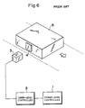
- the present invention relates to an article recognition system comprising a high-level controller, lower-level controllers connected to the higher-level controller, read/write heads, and a data carrier which is to be mounted on a moving article and which has a memory integrated therewith and loaded with identification data of the article.
- the data carrier 4 includes a memory (for example, EE-PROM) integrated therewith to store recognition data such that the data write or read operation on the memory is effected by use of a communication through an electromagnetic induction between the read/write head 3 and the data carrier 4, which is controlled by the lower-level controller 2 based on a command from the higher-level controller 1.
- a memory for example, EE-PROM
- the operation modes of the article recognition system includes, in addition to the ordinary read and write modes (in which the higher-level controller appropriately instructs the lower-level controller to detect an approach of the data carrier to the read/write head and to effect an access to the memory of the approaching data carrier so as to conduct the read/write operations), an auto read mode and an auto write mode.
- the auto read/write processing when an auto read (or an auto write) command is once transmitted from the higher-level controller 1 to the lower-level controller 2, the lower-level controller 2 catches or detects an approach of the data carrier 4 so as to effect a read (or write) operation on the pertinent data carrier.
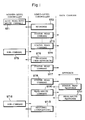
- the further detailed processing procedure of the conventional auto read (auto write) is as shown in FIG. 7.
- an auto read command is sent from the higher-level controller 1 (ST71) such that on receiving the auto read command, the lower-level controler 2 transmits a status read command to the data carrier 4 (ST72).
- the data carrier 4 is not at an approach position in a range where the read/write head 3 can effect a communication, no answer is returned from the data carrier 4.
- the lower-level controller 2 sends thereafter a status read command at a precetermined interval (ST73, ST74).
- the data carrier 4 approaches and enters a communicable range of the read/write head 3, and the data carrier 4 sends in response to the status read command a status read response (a text including status data stored in the memory of the data carrier 4) (ST76).
- the lower-level controller 2 recognizes that the data carrier 4 enters the communicable range and then sends a read command to the data carrier 4 (ST77).
- the data carreir 4 executes a read access to the memory and then returns a read response including data read out from the memory to the lower level controller 2 (ST78).
- the lower-level controller 2 sends a response including the read data to the higher-level controller 1 (ST79).
- the similar procedure is employed also in a case of the auto write.
- the article recognition system above shows the most fundamental configuration including a higher-level controller, a lower-level controller, and a read/write head.
- a higher-level controller a lower-level controller
- M read/write heads connected to each lower-level controller.
- the processing method associated with the conventional auto read/write modes described above is adopted, the auto read/write command is sent from the higher-level controller to the plural lower-level controllers; thereafter, the higher-level controller waits for an auto read/write response sent from the lower-level controllers.
- the period of time in which the auto read/write response is transmitted from the plural lowr-level controllers is not predetermined and hence cannot be determined, it is possible that there occurs a contention between auto responses from the lower-level controlers.
- the auto read (auto write) processing is achieved for a plurality of read/write heads connected to a lower-level controller, namely, there exists a fear that responses may collide with each other on a transmission path between the higher-level controler and the lower-level controllers.
- a recognition system is known from GB-A-2 190 525.
- a polling system corresponding to the communication between the higher level controller and the lower level controllers is known from US-A-4 710 616.
- the present invention is devised by paying attention to the problems above and it is therefore an object of the present invention to provide a recognition system in which the auto access can be simultaneously accomplished from a higher-level controller to a plurality of lower-level controllers and to a plurality of read/write heads.
- the invention is as defined in claim 1.
- FIG. 2 is a block diagram showing an article recognition system in which the present invention is effected.
- this article recognition system to a higher-level controller 1, there are connected a plurality of (N) lower-level controllers 2 -1 , 2 -2 , ..., 2 -N , and to each of the lower-level controllers 2 -1 , 2 -2 , ..., 2 -N , there are respectively connected M read/write heads 3 -1 , 3 -2 , ..., 3 -M such that before these read/write heads 3 -1 , 3 -2 . ..., 3 -M an arbitrary data carrier 4 passes at an arbitrary time.
- FIG. 3 shows a specific constitution of the system including the lower-level controller 2 -1 the read/write head 3 -1 , and the data carrier 4.
- the lower level-controller 2 -1 includes a higher-level transmission section 21 for effecting communications with the higher-level controller 1, a control circuit 22 for controlling the communications with the data carrier 4 based on commands from the higher-level controller 1, and a modem cicuit 23 for effecting communications with the data carrier 4.
- the control cirucit 22 comprises a CPU and a memory.
- the read/write head 3 -1 is provided with a transmit/receive circuit 31 integrated therewith.
- the other controllers and read/write heads are respectively of the similar configurations.
- the data carrier 4 includes a modem circuit 41 to be electromagnetically coupled with the read/write head, an encode/decode circuit 42 for decoding a carrier signal attained from the modem 41 and for encoding transmission data, a command memory controller 43 for controlling an EE-PROM 44 based on commands transmitted thereto, and the EE-PROM 44 for storing therein ID data of an article and other data.
- a modem circuit 41 to be electromagnetically coupled with the read/write head
- an encode/decode circuit 42 for decoding a carrier signal attained from the modem 41 and for encoding transmission data
- a command memory controller 43 for controlling an EE-PROM 44 based on commands transmitted thereto
- the EE-PROM 44 for storing therein ID data of an article and other data.
- an SRAM may be employed in place of the EE-PROM 44, there is required a backup battery in this case
- the characteristic of the article recognition system resides in that when an auto command specified with each controller unit number and a read/write head number is transmitted in a sequence of time from the higher-level contorller 1 to the respective lower-level controllers 2 -1 , 2 -2 , ..., 2 -N , and when each lower-level controller receives the auto command with a specification thereof, the lower-level controller repeatedly sends a status command via the specified read/write head until a status response is returned from the data carrier 4 at a predetetrmined interval. When the status response is returned from the data carrier 4, since the data carrier approaches the controller 2, a read/write command is next transmitted.
- the lower-level controller 2 temporarily stores and keeps the memory access data.
- the article recognition system is characterized in that the higher-level controler 1 sends, after the transmission of the auto command, a sub-command specified with each controller unit number to the respective lower-level controllers 2 -1 , 2 -2 , ..., 2 -N in a sequence of time.
- each lower-level controller sends, on receiving the sub-command with a specification thereof when the data carrier is not at an approached position, a response indicating the condition in response thereto to the higher-level controller 1; whereas when the response (including the memory access data) is already received from the data carrier and is temporarily stored, the lower-level controller returns an auto response including the memory access data thus retained to the higher-level controlelr.
- the formats of the auto read command, the sub-command, and the response to be used in the desscription below are as shown in FIG. 5 in which the auto read command includes a unit number of a specified lower-level controller, a header, a code specificaiton indicating the ASCII or HEX system, a read/write head number, a first address to be accessed in the memory of the data carrier, a byte count, and a terminator.
- the sub-command includes a unit number of a specified lower-level controller, a header, a code indicating whether the polling is continued or interrupted, a read/write header number, and a terminator.
- the auto read response comprises a unit number of a lower-level controller, a header, a termination code, read data, and a terminator.
- the termination code here is a code indicating a classification, namely, that the normal completion is detected, that the data carrier does approaches, that the initial polling auto command is received, or that the polling auto command processing is interrupted.
- an auto read/write command (either one of an auto read command and an auto write command) is sent from the higher-level controller 1 (ST1).
- the lower-level controller 2 On receiving the auto command, the lower-level controller 2 returns a response indicating the reception of the command to the higher-level controller 1 (ST2) and then sends a status read command via a specified read/write head 3 to the data carreir 4 (ST3).
- the data carrier 4 In a case where the data carrier 4 is not at an approach position within the communicable range of the specified read/write head 3, the data carrier 4 does not return the response. While the response is not returned, the lower-level controller 2 repeatedly effects a transmission of the status read command at a constant interval (ST3, ST4).
- the higher-level controller 1 sends, on receiving the response in reply to the auto command, after a predetermined period of time a sub-command to the lower-level controller 2 (ST5).
- the lower-level controller 2 having received the sub-command sends, in a case where no response is returned from the data carrier 4 in response to the status read command previously transmitted, namely, in a case where the data carrier does not approach the controller, a response indicating the condition to the higher-level controller 1 (ST6).
- the data carrier 4 when the data carrier 4 approaches, in response to the next status read command (ST8) sent from the lower-level controller 2, the data carrier 4 returns a status read response (ST9).
- the lower-level controller 2 sends a read command to the data carrier 4 (ST10).
- the data carrier 4 having received the read command conducts a read access to the memory (EE-PROM) and then returns a read response together with the data read out to the lower-level controller 2 (ST11).
- the lower-level controller 2 does not immediately return the read response and temporarily stores the response in the memory of the control circuit 22.
- the lower-level controller 2 sends a response of completion, namely, an auto read response including read data temporarily stored in the memory of the control circuit 22 in response thereto to the higher-level controller 1 (ST13).
- a response of completion namely, an auto read response including read data temporarily stored in the memory of the control circuit 22 in response thereto to the higher-level controller 1 (ST13).
- the case of the auto write command is basically the same as the case of the auto read command.
- each lower-level controller 2 when an auto read command from the higher-level controller 1 is received, a status read command is sent therefrom to the data carrier 4 at a predetermined interval such that when a status read response is returned from the data carrier 4, a read command is transmitted to the data carrier 4, and thereafter when a read response is returned from the data carrier 4, the read response is temporarily stored therein until a sub-command is transmitted from the higher-level controller 1; and then in response to the sub-command from the higher-level controller 1, the lower-level controller 2 returns a response of completion including the read response which is returned from the data carrier 4 and which is temporarily stored in the memory.
- FIG. 4 there is shown a communication example between a higher-level controller 1 and the first and second lower-level controllers 2 -1 and 2 -2 .
- the higher-level controller 1 sends, for example, an auto read command with a specification of the first lower-level controller 2 -1 (ST21).
- This auto read command also includes a specification indicating one of the read/write head (example: 3 -1 ) connected to the lower-level controller 2 -1 .
- the first lower-level controller 2 -1 returns a response of the reception (ST31).
- the higher-level controller 1 sends an auto read command to the second lower-level controller 2 -2 (ST22), which then returns a response thereto (ST41).
- the higher-level controller 1 generally transmits an auto command to a plurality of lower-level controllers.
- the higher-level controller 1 sequentially sends a sub-command to the lower-level controllers at a predetermined intervals (ST23, ST24, ).
- the lower-level controllers 2 -1 , 2 -2 , etc. repeat the transmission of a status read command via the specified read/write heads until a response is received from the data carrier 4 (ST31 to ST34; ST41 to ST44).
- the lower-level controller 2 -1 sends, if a response is not accepted from the data carreir 4, namely, if the data carrier is not at an approach position, when the sub-command thereto is received (ST23), a response indicating the condition to the higher-level controller 1 (ST35); thereafter, until the data carrier 4 becomes to an approach position, the transmission of the status command is reapeated (ST36 to ST38).
- the data carrier 4 receives a status read command from the lower-level controller 2 -2 and then returns a status read response to the lower-level controller 2 -2 (ST51).
- the lower-level controller 2 -2 sends a read command via the specified read/write head 3 -2 (ST45).
- the data carrier 4 On receiving the read command, the data carrier 4 effects a read access to the own memory (EE-PROM) 44 and then returns a read response together with the data read out to the lower-level controller 2 -2 (ST52).
- the lower-level controller 2 -2 temporarily stores the response thus transferred thereto, and thereafter, when a sub-command sent thereto from the higher-level controller 1 is received (ST24), a response of completion, namely, an auto read response is sent in response thereto to the higher-level controller 1.
- the data carrier first approaches the read/write head 3 -2 of the lower-level controller 2 -2 ; however, the similar operation is effected also in a case where the data carrier first approaches the other lower-level controller or the other read/write head.
- the lower-level controller controlling the read/write head for which the approach of the data carrier is detected temporarily stores a read response (or a write response) such that when a sub-command sent thereto is received, the lower-level controller transmits a response in reply thereto to the higher-level controller.
- each lower-level controller since each lower-level controller sends, when a sub-command with a specification thereof is received, a response to the higher-level controller, there does not occur a collision of the responses in a communication path between the higher-level controller and a plurality of lower-level controllers.
Landscapes
- Physics & Mathematics (AREA)
- General Physics & Mathematics (AREA)
- Engineering & Computer Science (AREA)
- General Engineering & Computer Science (AREA)
- Theoretical Computer Science (AREA)
- Warehouses Or Storage Devices (AREA)
- Eye Examination Apparatus (AREA)
- Acyclic And Carbocyclic Compounds In Medicinal Compositions (AREA)
- Geophysics And Detection Of Objects (AREA)
- Radar Systems Or Details Thereof (AREA)
Claims (1)
- Un système de reconnaissance qui comprend:un support (4) de données qui est attaché à un article en mouvement, ledit support de données comprenant une mémoire (44) pour y mémoriser des données qui incluent des données d'identification liées à l'article; etun système de commande (1, 2-1, 2-2, 2-N, 3-1, 3-2, 3-M) pour effectuer une opération d'écriture de données dans la mémoire dudit support de données ou de lecture de données dans cette mémoire, ledit système de commande incluant un dispositif de commande (1) de niveau supérieur, plusieurs dispositifs de commande (2-1, 2-2, 2-N) de niveau inférieur qui peuvent être mis en communication avec ledit dispositif de commande de niveau supérieur, et des têtes de lecture/écriture (3-1, 3-2, 3-M) dont au moins l'une est connectée à chacun desdits dispositifs de commande de niveau inférieur de façon à effectuer une communication de données avec ledit support de données, ledit système de reconnaissance étant adapté d'une manière telle que:ledit support (4) de données effectue, lorsqu'un premier ordre (ST10, ST45) de lecture/d'écriture est reçu de l'un quelconque des dispositifs de commande de niveau inférieur, un accès à la mémoire (44) de façon à réaliser en réponse au premier ordre de lecture/écriture un traitement de lecture/écriture associé à cet ordre en envoyant ainsi audit quelconque dispositif de commande de niveau inférieur une réponse (ST1, ST52) qui inclut un résultat du traitement de lecture/écriture,ledit dispositif de commande (1) de niveau supérieur envoie en séquence à ladite série de dispositifs de commande (2-1, 2-2, 2-N) de niveau inférieur un ordre de lecture/écriture automatique (ST1, ST21, ST22) accompagné d'une désignation d'un dispositif de commande de niveau inférieur,ledit dispositif de commande de niveau inférieur désigné par l'ordre de lecture/écriture automatique (ST1, ST21, ST22) envoie de façon répétée à un intervalle prédéterminé, au moyen de ladite tête de lecture/écriture qui lui est associée, un ordre de lecture d'état (ST3, ST4, ST7-8, ST32-34, ST36-38, ST42-44) jusqu'à ce qu'il reçoive une réponse de lecture d'état (ST9, ST51) renvoyée à partir dudit support de données, ce qui confirme l'approche dudit support de données, et envoie ledit premier ordre de lecture/écriture (ST10, ST45) par l'intermédiaire de ladite tête de lecture/écriture audit support (4) de données lorsque l'approche dudit support (4) de données est confirmée, et reçoit une réponse (ST11, ST52) renvoyée par ledit support (4) de données en réponse au premier ordre de lecture/écriture, et mémorise le contenu de la réponse reçue,ledit dispositif de commande (1) de niveau supérieur transmet en séquence un sous-ordre (ST5, ST12, ST23, ST24) accompagné d'une désignation d'un dispositif de commande de niveau inférieur (2-1, 2-2, 2-N) spécifié par l'ordre de lecture/écriture automatique,ledit dispositif de commande de niveau inférieur (2-1, 2-2, 2-N) envoie audit dispositif de commande de niveau supérieur, en réponse au sous-ordre qui désigne ledit dispositif de commande de niveau inférieur, une réponse automatique (ST46, ST13) qui inclut le contenu de la réponse qui a été reçue dudit support de données et est mémorisée dans ledit dispositif de commande de niveau inférieur,caractérisé en ce queune série desdites têtes de lecture/écriture (3-1, 3-2, 3-M) est connectée à chacun desdits dispositifs de commande (2-1, 2-2, 2-N) desdits dispositifs de commande de niveau inférieur,ledit dispositif de commande (1) de niveau inférieur envoie en outre audit dispositif de commande de niveau inférieur désigné l'ordre de lecture/écriture automatique (ST1, ST21, ST22) qui désigne une tête de lecture/écriture, ladite tête de lecture/écriture étant connectée au dispositif de commande désigné de niveau inférieur,ledit dispositif de commande désigné de niveau inférieur (2-1, 2-2, 2-N) envoie l'ordre de lecture d'état (ST3, ST4, ST7, ST32-34, ST36-38, ST42-44) par l'intermédiaire de ladite tête désignée de lecture/écriture et envoie ledit premier ordre de lecture/écriture (ST10, ST45) par l'intermédiaire de ladite tête désignée de lecture/écriture qui a reçu la réponse de lecture d'état (ST9, ST51) renvoyée en réponse à l'ordre de lecture d'état.
Applications Claiming Priority (2)
| Application Number | Priority Date | Filing Date | Title |
|---|---|---|---|
| JP111859/88 | 1988-05-09 | ||
| JP63111859A JPH01282486A (ja) | 1988-05-09 | 1988-05-09 | 認識システムのデータ処理方式 |
Publications (3)
| Publication Number | Publication Date |
|---|---|
| EP0341665A2 EP0341665A2 (fr) | 1989-11-15 |
| EP0341665A3 EP0341665A3 (fr) | 1992-01-08 |
| EP0341665B1 true EP0341665B1 (fr) | 1996-08-14 |
Family
ID=14571948
Family Applications (1)
| Application Number | Title | Priority Date | Filing Date |
|---|---|---|---|
| EP89108332A Expired - Lifetime EP0341665B1 (fr) | 1988-05-09 | 1989-05-09 | Système de reconnaissance |
Country Status (5)
| Country | Link |
|---|---|
| US (1) | US4941181A (fr) |
| EP (1) | EP0341665B1 (fr) |
| JP (1) | JPH01282486A (fr) |
| AT (1) | ATE141428T1 (fr) |
| DE (1) | DE68926928T2 (fr) |
Families Citing this family (15)
| Publication number | Priority date | Publication date | Assignee | Title |
|---|---|---|---|---|
| FR2678089B1 (fr) * | 1991-06-24 | 1993-10-15 | Yves Nouailhetas | Procede de marquage actif applique a la surveillance, au controle et a la gestion de documents ou d'objets de valeur. |
| US5469361A (en) * | 1991-08-08 | 1995-11-21 | The Board Of Regents Acting For And On Behalf Of The University Of Michigan | Generic cell controlling method and apparatus for computer integrated manufacturing system |
| JPH05209959A (ja) * | 1992-01-31 | 1993-08-20 | Matsushita Electric Works Ltd | 移動体識別装置 |
| JPH07296125A (ja) * | 1994-04-28 | 1995-11-10 | Mitsubishi Denki Semiconductor Software Kk | リーダライタ及び非接触icカードシステム |
| GB9615057D0 (en) * | 1996-07-18 | 1996-09-04 | Newman Paul B D | Identification and tracking of carcasses and primal cuts of meat |
| JP4504053B2 (ja) * | 2004-03-15 | 2010-07-14 | 株式会社三宅 | 非接触idタグ書き込み装置 |
| US7243002B1 (en) | 2004-03-27 | 2007-07-10 | Translogic Corporation | System and method for carrier identification in a pneumatic tube system |
| ATE547766T1 (de) * | 2004-10-15 | 2012-03-15 | Nxp Bv | Verfahren zum betrieb eines rfid-systems |
| US8793014B2 (en) * | 2008-10-09 | 2014-07-29 | Translogic Corporation | Pneumatic transport delivery control |
| US8382401B2 (en) * | 2008-10-09 | 2013-02-26 | Translogic Corporation | Variable diameter pneumatic tube brake |
| US8317432B2 (en) * | 2008-10-09 | 2012-11-27 | Translogic Corporation | Air valve pneumatic tube carrier system |
| US9139383B2 (en) | 2012-09-13 | 2015-09-22 | Translogic Corporation | Control of pneumatic carrier system based on carrier or payload identification |
| US9650214B2 (en) | 2013-03-15 | 2017-05-16 | Translogic Corporation | Multiple carrier handling in a pneumatic transport system |
| US9439996B2 (en) | 2014-02-28 | 2016-09-13 | Translogic Corporation | Light source disinfection in a pneumatic transport system |
| US11059681B2 (en) * | 2019-05-17 | 2021-07-13 | Carl P. Lathan | Systems and methods for pneumatic tube smart carrier tracking |
Family Cites Families (10)
| Publication number | Priority date | Publication date | Assignee | Title |
|---|---|---|---|---|
| CH540533A (de) * | 1971-07-08 | 1973-08-15 | Zellweger Uster Ag | Verfahren und Vorrichtung zum Steuern der Lichtquelle einer optischen Lesevorrichtung |
| JPS5717012A (en) * | 1980-07-07 | 1982-01-28 | Fanuc Ltd | Numerical controller |
| US4577344A (en) * | 1983-01-17 | 1986-03-18 | Automatix Incorporated | Vision system |
| DE3504013A1 (de) * | 1985-02-06 | 1986-08-07 | Jagenberg AG, 4000 Düsseldorf | Positioniereinrichtung fuer mehrere, nebeneinander und auf gegenseitigen abstand verfahrbare einheiten |
| HUT43774A (en) * | 1986-05-15 | 1987-11-30 | Koezponti Banyaszati Fejleszte | Method and apparatus for automatic identification living beings and objects |
| US4710616A (en) * | 1986-06-02 | 1987-12-01 | National Transdata Systems, Inc. | Multi-station data collection system |
| JP2504961B2 (ja) * | 1986-07-10 | 1996-06-05 | 豊田工機株式会社 | プログラマブルトランスファマシン |
| US4837704A (en) * | 1986-09-10 | 1989-06-06 | International Business Machines Corporation | Computer controlled material handling |
| JPH0664576B2 (ja) * | 1986-09-10 | 1994-08-22 | インタ−ナショナル・ビジネス・マシ−ンズ・コ−ポレ−ション | 材料搬送制御装置及び方法 |
| US4827425A (en) * | 1986-10-31 | 1989-05-02 | Thorn Emi Malco, Incorporated | System for personalization of integrated circuit microchip cards |
-
1988
- 1988-05-09 JP JP63111859A patent/JPH01282486A/ja active Pending
-
1989
- 1989-05-02 US US07/346,659 patent/US4941181A/en not_active Expired - Lifetime
- 1989-05-09 EP EP89108332A patent/EP0341665B1/fr not_active Expired - Lifetime
- 1989-05-09 DE DE68926928T patent/DE68926928T2/de not_active Expired - Fee Related
- 1989-05-09 AT AT89108332T patent/ATE141428T1/de not_active IP Right Cessation
Also Published As
| Publication number | Publication date |
|---|---|
| EP0341665A3 (fr) | 1992-01-08 |
| DE68926928T2 (de) | 1997-04-03 |
| EP0341665A2 (fr) | 1989-11-15 |
| US4941181A (en) | 1990-07-10 |
| DE68926928D1 (de) | 1996-09-19 |
| JPH01282486A (ja) | 1989-11-14 |
| ATE141428T1 (de) | 1996-08-15 |
Similar Documents
| Publication | Publication Date | Title |
|---|---|---|
| EP0341665B1 (fr) | Système de reconnaissance | |
| US6456191B1 (en) | Tag system with anti-collision features | |
| EP0694860B1 (fr) | Appareil et méthode pour identifier une multiplicité de transpondeurs | |
| EP0322701B1 (fr) | Système d'identification des sources mobiles de données | |
| US20120126952A1 (en) | Communication Method in RFID or Remote Sensor Systems | |
| US6919793B2 (en) | Radio frequency identification system write broadcast capability | |
| JP3017995B2 (ja) | 複数アイテム無線周波数タグ識別プロトコル | |
| US6535109B1 (en) | System and method for communicating with multiple transponders | |
| EP0686928A2 (fr) | Système et méthode d'initialisation de communications entre un contrÔleur et un sous-ensemble selectionné de plusieurs transpondeurs dans une champ commun à radio-fréquences | |
| US6411200B1 (en) | Card reader/writer and communication method of card reader writer | |
| US7616094B2 (en) | Radio frequency identification system with write broadcast capability | |
| RU2210109C2 (ru) | Способ идентификации множества транспондеров, анализирующее устройство и транспондер | |
| EP0553905B1 (fr) | Méthode d'échange d'information entre une station de détection et au moins un label dans un système d'identification/communication, système d'application de la méthode, et label et station de détection à utiliser dans le système, et méthode à identifier labels différents par une station de détection dans le système d'identification/communication | |
| EP1527408B1 (fr) | Procede d'anticollision permettant de marquer des intervalles temporels | |
| EP1772972B1 (fr) | Système de lecture d'étiquette radio, dispositif de lecture d'étiquette radio, et étiquette radio | |
| AU755365B2 (en) | Improved method for collision management in a non-contact data exchange system | |
| US20050128130A1 (en) | Method for selecting transponders | |
| JP2000101472A (ja) | 通信システム | |
| JPS635286A (ja) | 遠隔識別装置におけるデ−タ伝送方式 | |
| CA2266337C (fr) | Systeme d'etiquettes avec des caracteristiques anti-collision | |
| JPH0869583A (ja) | 移動体識別方法 | |
| JP2003150915A (ja) | 非接触通信システム及びこれに使用するデータキャリア | |
| EP0548977B1 (fr) | Appareil et procédé de transmission multiplex | |
| US5479406A (en) | Data communication system and method | |
| JPS63231501A (ja) | Idシステムのデータ読出し制御方法 |
Legal Events
| Date | Code | Title | Description |
|---|---|---|---|
| PUAI | Public reference made under article 153(3) epc to a published international application that has entered the european phase |
Free format text: ORIGINAL CODE: 0009012 |
|
| 17P | Request for examination filed |
Effective date: 19890509 |
|
| AK | Designated contracting states |
Kind code of ref document: A2 Designated state(s): AT BE CH DE ES FR GB GR IT LI NL SE |
|
| PUAL | Search report despatched |
Free format text: ORIGINAL CODE: 0009013 |
|
| AK | Designated contracting states |
Kind code of ref document: A3 Designated state(s): AT BE CH DE ES FR GB GR IT LI NL SE |
|
| 17Q | First examination report despatched |
Effective date: 19931104 |
|
| GRAH | Despatch of communication of intention to grant a patent |
Free format text: ORIGINAL CODE: EPIDOS IGRA |
|
| RAP1 | Party data changed (applicant data changed or rights of an application transferred) |
Owner name: OMRON CORPORATION |
|
| GRAA | (expected) grant |
Free format text: ORIGINAL CODE: 0009210 |
|
| GRAH | Despatch of communication of intention to grant a patent |
Free format text: ORIGINAL CODE: EPIDOS IGRA |
|
| AK | Designated contracting states |
Kind code of ref document: B1 Designated state(s): AT BE CH DE ES FR GB GR IT LI NL SE |
|
| PG25 | Lapsed in a contracting state [announced via postgrant information from national office to epo] |
Ref country code: IT Free format text: LAPSE BECAUSE OF FAILURE TO SUBMIT A TRANSLATION OF THE DESCRIPTION OR TO PAY THE FEE WITHIN THE PRE;WARNING: LAPSES OF ITALIAN PATENTS WITH EFFECTIVE DATE BEFORE 2007 MAY HAVE OCCURRED AT ANY TIME BEFORE 2007. THE CORRECT EFFECTIVE DATE MAY BE DIFFERENT FROM THE ONE RECORDED.SCRIBED TIME-LIMIT Effective date: 19960814 Ref country code: FR Effective date: 19960814 Ref country code: GR Free format text: LAPSE BECAUSE OF FAILURE TO SUBMIT A TRANSLATION OF THE DESCRIPTION OR TO PAY THE FEE WITHIN THE PRESCRIBED TIME-LIMIT Effective date: 19960814 Ref country code: AT Effective date: 19960814 Ref country code: LI Effective date: 19960814 Ref country code: CH Effective date: 19960814 Ref country code: BE Effective date: 19960814 Ref country code: ES Free format text: THE PATENT HAS BEEN ANNULLED BY A DECISION OF A NATIONAL AUTHORITY Effective date: 19960814 |
|
| REF | Corresponds to: |
Ref document number: 141428 Country of ref document: AT Date of ref document: 19960815 Kind code of ref document: T |
|
| REF | Corresponds to: |
Ref document number: 68926928 Country of ref document: DE Date of ref document: 19960919 |
|
| PG25 | Lapsed in a contracting state [announced via postgrant information from national office to epo] |
Ref country code: SE Effective date: 19961114 |
|
| EN | Fr: translation not filed | ||
| REG | Reference to a national code |
Ref country code: CH Ref legal event code: PL |
|
| PLBE | No opposition filed within time limit |
Free format text: ORIGINAL CODE: 0009261 |
|
| STAA | Information on the status of an ep patent application or granted ep patent |
Free format text: STATUS: NO OPPOSITION FILED WITHIN TIME LIMIT |
|
| 26N | No opposition filed | ||
| REG | Reference to a national code |
Ref country code: GB Ref legal event code: 746 Effective date: 20000503 |
|
| REG | Reference to a national code |
Ref country code: GB Ref legal event code: IF02 |
|
| PGFP | Annual fee paid to national office [announced via postgrant information from national office to epo] |
Ref country code: NL Payment date: 20070510 Year of fee payment: 19 |
|
| PGFP | Annual fee paid to national office [announced via postgrant information from national office to epo] |
Ref country code: DE Payment date: 20070531 Year of fee payment: 19 |
|
| PGFP | Annual fee paid to national office [announced via postgrant information from national office to epo] |
Ref country code: GB Payment date: 20070511 Year of fee payment: 19 |
|
| GBPC | Gb: european patent ceased through non-payment of renewal fee |
Effective date: 20080509 |
|
| PG25 | Lapsed in a contracting state [announced via postgrant information from national office to epo] |
Ref country code: NL Free format text: LAPSE BECAUSE OF NON-PAYMENT OF DUE FEES Effective date: 20081201 |
|
| PG25 | Lapsed in a contracting state [announced via postgrant information from national office to epo] |
Ref country code: DE Free format text: LAPSE BECAUSE OF NON-PAYMENT OF DUE FEES Effective date: 20081202 |
|
| PG25 | Lapsed in a contracting state [announced via postgrant information from national office to epo] |
Ref country code: GB Free format text: LAPSE BECAUSE OF NON-PAYMENT OF DUE FEES Effective date: 20080509 |