EP0341665A2 - Système de reconnaissance - Google Patents
Système de reconnaissance Download PDFInfo
- Publication number
- EP0341665A2 EP0341665A2 EP89108332A EP89108332A EP0341665A2 EP 0341665 A2 EP0341665 A2 EP 0341665A2 EP 89108332 A EP89108332 A EP 89108332A EP 89108332 A EP89108332 A EP 89108332A EP 0341665 A2 EP0341665 A2 EP 0341665A2
- Authority
- EP
- European Patent Office
- Prior art keywords
- level controller
- read
- command
- data carrier
- response
- Prior art date
- Legal status (The legal status is an assumption and is not a legal conclusion. Google has not performed a legal analysis and makes no representation as to the accuracy of the status listed.)
- Granted
Links
Images


Classifications
-
- G—PHYSICS
- G07—CHECKING-DEVICES
- G07C—TIME OR ATTENDANCE REGISTERS; REGISTERING OR INDICATING THE WORKING OF MACHINES; GENERATING RANDOM NUMBERS; VOTING OR LOTTERY APPARATUS; ARRANGEMENTS, SYSTEMS OR APPARATUS FOR CHECKING NOT PROVIDED FOR ELSEWHERE
- G07C3/00—Registering or indicating the condition or the working of machines or other apparatus, other than vehicles
-
- G—PHYSICS
- G06—COMPUTING; CALCULATING OR COUNTING
- G06K—GRAPHICAL DATA READING; PRESENTATION OF DATA; RECORD CARRIERS; HANDLING RECORD CARRIERS
- G06K17/00—Methods or arrangements for effecting co-operative working between equipments covered by two or more of main groups G06K1/00 - G06K15/00, e.g. automatic card files incorporating conveying and reading operations
- G06K17/0022—Methods or arrangements for effecting co-operative working between equipments covered by two or more of main groups G06K1/00 - G06K15/00, e.g. automatic card files incorporating conveying and reading operations arrangements or provisious for transferring data to distant stations, e.g. from a sensing device
Definitions
- the present invention relates to a data processing method of an article recognition system comprising a high-level controller, lower-level controllers connected to the higher-level controller, read/write heads, and a data carrier which is to be mounted on a moving article and which has a memory integrated therwith and loaded with identification data of the article.
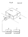
- the data carrier 4 includes a memory (for example EE-PROM) integrated therewith to store recognition data such that the data write or read operation on the memory is effected by use of a communication through an electromagnetic induction between the read/write head 3 and the data carrier 4, which is controlled by the lower-level controller 2 based on a command from the higher-level controller 1.
- a memory for example EE-PROM
- the operation modes of the article recognition system includes, in addition to the ordinary read and write modes (in which the higher-level controller appropriately instructs the lower-level controller to detect an approach of the data carrier to the read/write head and to effect an access to the memory of the approaching data carrier so as to conduct the read/write operations), an auto read mode and an auto write mode.
- the auto read/write processing when an auto read (or an auto write) command is once transmitted from the higher-level controller 1 to the lower-level controller 2, the lower-level controller 2 catches or detects an approach of the data carrier 4 so as to effect a read (or write) operation on the pertinent data carrier.
- the further detailed processing procedure of the conventional auto read (auto write) is as shown in FIG. 7.
- an auto read command is sent from the higher-level controller 1 (ST71) such that on receiving the auto read command, the lower-level controler 2 transmits a status read command to the data carrier 4 (ST72).
- the data carrier 4 is not at an approach position in a range where the read/write head 3 can effect a communication, no answer is returned from the data carrier 4.
- the lower-level controller 2 sends thereafter a status read command at a precetermined interval (ST73, ST74).
- the data carrier 4 approaches and enters a communicable range of the read/write head 3, and the data carrier 4 sends in response to the status read command a status read response (a text including status data stored in the memory of the data carrier 4) (ST76).
- the lower-level controller 2 recognizes that the data carrier 4 enters the communicable range and then sends a read command to the data carrier 4 (ST77).
- the data carreir 4 executes a read access to the memory and then returns a read response including data read out from the memory to the lower level controller 2 (ST78).
- the lower-level controller 2 sends a response including the read data to the higher-level controller 1 (ST79).
- the similar procedure is employed also in a case of the auto write.
- the article recognition system above shows the most fundamental configuration including a higher-level controller, a lower-level controller, and a read/write head.
- a higher-level controller a lower-level controller
- M read/write heads connected to each lower-level controller.
- the processing method associated with the conventional auto read/write modes described above is adopted, the auto read/write command is sent from the higher-level controller to the plural lower-level controllers; thereafter, the higher-level controller waits for an auto read/write response sent from the lower-level controllers.
- the period of time in which the auto read/write response is transmitted from the plural lowr-level controllers is not predetermined and hence cannot be determined, it is possible that there occurs a contention between auto responses from the lower-level controlers.
- the auto read (auto write) processing is achieved for a plurality of read/write heads connected to a lower-level controller, namely, there exists a fear that responses may collide with each other on a transmission path between the higher-level controler and the lower-level controllers.
- the present invention is devised by paying attention to the problems above and it is therefore an object of the present invention to provide a data processing method in a recognition system in which the auto access can be simultaneously accomplished from a higher-level controller to a plurality of lower-level controllers and to a plurality of read/write heads.
- the processing is achieved such that the higher-level controller specifies the lower-level controllers in a predetermined order so as to sequentially send thereto an auto read/write command (namely, either one of an auto read command or an auto write command ) and thereafter specifies the lower-level controllers in a predetermined order so as to sequentially send a sub-command thereto, that each said lower-level controller receiving the auto read/write command sent thereto repeatedly sends a command to confirm an approach of the data carrier until the approach of the data carrier is confirmed, that when the approach of
- an auto read/write command is sent from the higher-level controller to the plural lower-level controllers.
- each lower-level controller respectively sends a command to confirm an approach of the data carrier, for example, a status read command via a read/write head.
- the transmission of the status read command is repeated at a predetermined interval until the data carrier approaches.
- the lower-level controller transmits a read/write command to the data carrier through a read/write head.
- the data carrier effects a read/write access to the memory so as to return a read/write response with data related to the read/write operation to the lower-level controller. In the lower-level controller, the read/write response is temporarily retained.
- the higher-level controller after the transmission of the auto read/write command, a sub-command is sent to the respective lower-level controllers in a predetermined order.
- Each lower-level controller on receiving the sub-command with a specification thereof, returns an auto read/write response including the content of the read/write response thus retained to the higher-level controller if a read/write response has already been received from the data carrier, whereas if the read/write response has not been received yet, the lower-level controller returns a response indicating the condition.
- a command for confirming an approach of a data carrier is repeatedly transmitted independently by each read/write head.
- the lower-level controller causes the data carrier to achieve a memory access and then a response obtained therefrom is temporarily stored.
- the lower-level controller sends in response to a sub-command sent thereto, a response including the content temporarily stored to the higher-level controller; in consequence, there does not occur a collision between the responses of the higher-level controller and the lower-level controllers, which enables the communication to be accomplished with a high efficiency.
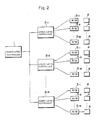
- FIG. 2 is a block diagram showing an article recognition system in which the present invention is effected.
- this article recognition system to a higher-level controller 1, there are connected a plurality of (N) lower-level controllers 2 ⁇ 1, 2 ⁇ 2, ..., 2 -N , and to each of the lower-level controllers 2 ⁇ 1, 2 ⁇ 2, ..., 2 -N , there are respectively connected M read/write heads 3 ⁇ 1, 3 ⁇ 2, ..., 3 -M such that before these read/write heads 3 ⁇ 1, 3 ⁇ 2. ..., 3 -M an arbitrary data carrier 4 passes at an arbitrary time.
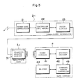
- FIG. 3 shows a specific constitution of the system including the lower-level controller 2 ⁇ 1 the read/write head 3 ⁇ 1, and the data carrier 4.
- the lower level-controller 2 ⁇ 1 includes a higher-level transmission section 21 for effecting communications with the higher-level controller 1, a control circuit 22 for controlling the communications with the data carreir 4 based on commands from the higher-level controller 1, and a modem cicuit 23 for effecting communications with the data carrier 4.
- the control cirucit 22 comprises a CPU and a memory.
- the read/write head 3 ⁇ 1 is provided with a transmit/receive circuit 31 integrated therewith.
- the other controllers and read/write heads are respectively of the similar configurations.
- the data carrier 4 inlcudes a modem circuit 41 to be electromagnetically coupled with the read/write head, an encode/decode circuit 42 for decoding a carrier signal attained from the modem 41 and for encoding transmission data, a command memory controller 43 for controlling an EE-PROM 44 based on commands transmitted thereto, and the EE-PROM 44 for storing therein ID data of an article and other data.
- a modem circuit 41 to be electromagnetically coupled with the read/write head
- an encode/decode circuit 42 for decoding a carrier signal attained from the modem 41 and for encoding transmission data
- a command memory controller 43 for controlling an EE-PROM 44 based on commands transmitted thereto
- the EE-PROM 44 for storing therein ID data of an article and other data.
- an SRAM may be employed in place of the EE-PROM 44, there is required a backup battery in this case
- the characteristic of the article recognition system resides in that when an auto command specified with each controller unit number and a read/write head number is transmitted in a sequence of time from the higher-level contorller 1 to the respective lower-level controllers 2 ⁇ 1, 2 ⁇ 2, ..., 2 -N , and when each lower-level controller receives the auto command with a specification thereof, the lower-level controller repeatedly sends a status command via the specified read/write head until a status response is returned from the data carrier 4 at a predetetrmined interval. When the status response is returned from the data carrier 4, since the data carrier approaches the controller 2, a read/write command is next ransmitted.
- the lower-level controller 2 temporarily stores and keeps the memory access data.
- the article recognition system is characterized in that the higher-level controler 1 sends, after the transmission of the auto command, a sub-command specified with each controller unit number to the respective lower-level controllers 2 ⁇ 1, 2 ⁇ 2, ..., 2 -N in a sequence of time.
- each lower-level controller sends, on receiving the sub-command with a specification thereof when the data carrier is not at an approached position, a response indicating the condition in response thereto to the higher-level controller 1; whereas when the response (including the memory access data) is already received from the data carrier and is temporarily stored, the lower-level controller returns an auto response including the memory access data thus retained to the higher-level controlelr.
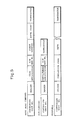
- the formats of the auto read command, the sub-command, and the response to be used in the desscription below are as shown in FIG. 5 in which the auto read command inlcudes a unit number of a specified lower-level controller, a header, a code specificaiton indicating the ASCII or HEX system, a read/write head number, a first address to be accessed in the memory of the data carrier, a byte count, and a terminator.
- the sub-commnad includes a unit number of a specified lower-level controller, a header, a code indicating whether the polling is continued or interrupted, a read/write header number, and a terminator.
- the auto read response comprises a unit number of a lower-level controller, a header, a termination code, read data, and a terminator.
- the termination code here is a code indicating a classification, namely, that the normal completion is detected, that the data carrier does approaches, that the initial polling auto command is received, or that the polling auto command processing is interrupted.
- an auto read/write command (either one of an auto read command and an auto write command) is sent from the higher-level controller 1 (ST1).
- the lower-level controller 2 On receiving the auto command, the lower-level controller 2 returns a response indicating the reception of the command to the higher-level controller 1 (ST2) and then sends a status read command via a specified read/write head 3 to the data carreir 4 (ST3).
- the data carrier 4 is not at an approach position within the communicable range of the specified read/write head 3, the data carreir 4 does not return the response.
- the lowr-level controller 2 repeatedly effects a transmission of the status read command at a constant interval (ST3, ST4).
- the higher-level controller 1 sends, on receiving the response in reply to the auto command, after a predetermined period of time a sub-command to the lower-level controller 2 (ST5).
- the lower-level controller 2 having received the sub-command sends, in a case where no response is returned from the data carrier 4 in response to the status read command previously transmitted, namely, in a case where the data carrier does not approach the controller, a response indicating the condition to the higher-level controller 1 (ST6).
- the data carrier 4 when the data carrier 4 approaches, in response to the next status read command (ST8) sent from the lower-level controller 2, the data carrier 4 returns a status read response (ST9).
- the lower-level controller 2 sends a read command to the data carrier 4 (ST10).
- the data carrier 4 having received the read command conducts a read access to the memory (EE-PROM) and then returns a read response together with the data read out to the lower-level controller 2 (ST11).
- the lower-level controller 2 does not immediately return the read response and temporarily stores the response in the memory of the control circuit 22.
- the lower-level controller 2 sends a response of completion, namely, a auto read response including read data temporarily stored in the memory of the control circuit 22 in response thereto to the higher-level controller 1 (ST13).
- a response of completion namely, a auto read response including read data temporarily stored in the memory of the control circuit 22 in response thereto to the higher-level controller 1 (ST13).
- the case of the auto write command is basically the same as the case of the auto read command.
- each lower-level controller 2 when an auto read command from the hier-level controller 1 is received, a status read command is sent therefrom to the data carreir 4 at a predetermined interval such that when a status read response is returned from the data carrier 4, a read command is transmitted to the data carrier 4, and thereafter when a read response is returned from the data carrier 4, the read response is temporarily stored therein until a sub-command is transmitted from the higher-level controller 1; and then in response to the sub-command from the higher-level controller 1, the lower-level controller 2 returns a response of completion including the read response which is returned from the data carrier 4 and which is temporarily stored in the memory.
- FIG. 4 there is shown a communication example between a higher-level controller 1 and the first and second lower-level controllers 2 ⁇ 1 and 2 ⁇ 2.
- the higher-level controller 1 sends, for example, an auto read command with a specification of the first lower-level controller 2 ⁇ 1 (ST21).
- This auto read command also includes a specification indicating one of the read/write head (example: 3 ⁇ 1) connected to the lower-level controller 2 ⁇ 1.
- the first lower-level controller 2 ⁇ 1 returns a response of the reception (ST31).
- the higher-level controller 1 sends an auto read command to the second lower-level controller 2 ⁇ 2 (ST22), which then returns a response thereto (ST41).
- the higher-level controller 1 generally transmits an atuto command to a plurality of lower-level controllers.
- the higher-level controller 1 sequentially sends a sub-command to the lower-level controllers at a predetermined intervals (ST23, ST24, ).
- the lower-level controllers 2 ⁇ 1, 2 ⁇ 2, etc. repeat the transmission of a status read command via the specified read/write heads until a response is received from the data carrier 4 (ST31 to ST34; ST41 to ST44).
- the lower-level controller 2 ⁇ 1 sends, if a response is not accepted from the data carreir 4, namely, if the data carrier is not at an approach position, when the sub-command thereto is received (ST23), a response indicating the condition to the higher-level controller 1 (ST35); thereafter, until the data carrier 4 becomes to an approach position, the transmission of the status command is reapeated (ST36 to ST38).
- the data carrier 4 receives a status read command from the lower-level controller 2 ⁇ 2 and then returns a status read response to the lower-level controller 2 ⁇ 2 (ST51).
- the lower-level controller 2 ⁇ 2 sends a read command via the specified read/write head 3 ⁇ 2 (ST45).
- the data carrier 4 On receiving the read command, the data carrier 4 effects a read access to the own memory (EE-PROM) 44 and then returns a read response together with the data read out to the lower-level controller 2 ⁇ 2 (ST52).
- the lower-level controller 2 ⁇ 2 temporarily stores the response thus transferred thereto, and thereafter, when a sub-command sent thereto from the higher-level controller 1 is received (ST24), a response of completion, namely, an auto read response is sent in response thereto to the higher-level controller 1.
- the data carrier first approaches the read/write head 3 ⁇ 2 of the lower-level controller 2 ⁇ 2; however, the similar operation is effected also in a case where the data carrier first appreaches the other lower-level controller or the other read/write head.
- the lower-level controller controlling the read/write head for which the approach of the data carrier is detected temporarily stores a read response (or a write response) such that when a sub-command sent thereto is received, the lower-level controller transmits a response in reply thereto to the higher-level controller.
- each lower-level controller since each lower-level controller sends, when a sub-command with a specification thereof is received, a response to the higher-level controller, there does not occur a collision of the responses in a communication path between the higher-level controller and a plurality of lower-level controllers.
Landscapes
- Physics & Mathematics (AREA)
- General Physics & Mathematics (AREA)
- Engineering & Computer Science (AREA)
- General Engineering & Computer Science (AREA)
- Theoretical Computer Science (AREA)
- Warehouses Or Storage Devices (AREA)
- Eye Examination Apparatus (AREA)
- Acyclic And Carbocyclic Compounds In Medicinal Compositions (AREA)
- Geophysics And Detection Of Objects (AREA)
- Radar Systems Or Details Thereof (AREA)
Applications Claiming Priority (2)
| Application Number | Priority Date | Filing Date | Title |
|---|---|---|---|
| JP63111859A JPH01282486A (ja) | 1988-05-09 | 1988-05-09 | 認識システムのデータ処理方式 |
| JP111859/88 | 1988-05-09 |
Publications (3)
| Publication Number | Publication Date |
|---|---|
| EP0341665A2 true EP0341665A2 (fr) | 1989-11-15 |
| EP0341665A3 EP0341665A3 (fr) | 1992-01-08 |
| EP0341665B1 EP0341665B1 (fr) | 1996-08-14 |
Family
ID=14571948
Family Applications (1)
| Application Number | Title | Priority Date | Filing Date |
|---|---|---|---|
| EP89108332A Expired - Lifetime EP0341665B1 (fr) | 1988-05-09 | 1989-05-09 | Système de reconnaissance |
Country Status (5)
| Country | Link |
|---|---|
| US (1) | US4941181A (fr) |
| EP (1) | EP0341665B1 (fr) |
| JP (1) | JPH01282486A (fr) |
| AT (1) | ATE141428T1 (fr) |
| DE (1) | DE68926928T2 (fr) |
Cited By (2)
| Publication number | Priority date | Publication date | Assignee | Title |
|---|---|---|---|---|
| FR2678089A1 (fr) * | 1991-06-24 | 1992-12-24 | Nouailhetas Yves | Procede de marquage actif applique a la surveillance, au controle et a la gestion de documents ou d'objets de valeur. |
| EP0680002A3 (fr) * | 1994-04-28 | 1996-07-24 | Mitsubishi Electric Corp | Dispositif de lecture et d'écriture et système de carte à circuits intégrés sans contact. |
Families Citing this family (13)
| Publication number | Priority date | Publication date | Assignee | Title |
|---|---|---|---|---|
| US5469361A (en) * | 1991-08-08 | 1995-11-21 | The Board Of Regents Acting For And On Behalf Of The University Of Michigan | Generic cell controlling method and apparatus for computer integrated manufacturing system |
| JPH05209959A (ja) * | 1992-01-31 | 1993-08-20 | Matsushita Electric Works Ltd | 移動体識別装置 |
| GB9615057D0 (en) * | 1996-07-18 | 1996-09-04 | Newman Paul B D | Identification and tracking of carcasses and primal cuts of meat |
| JP4504053B2 (ja) * | 2004-03-15 | 2010-07-14 | 株式会社三宅 | 非接触idタグ書き込み装置 |
| US7243002B1 (en) * | 2004-03-27 | 2007-07-10 | Translogic Corporation | System and method for carrier identification in a pneumatic tube system |
| EP1803083B1 (fr) * | 2004-10-15 | 2012-02-29 | Nxp B.V. | Procede d'exploitation d'un systeme rfid |
| US8793014B2 (en) | 2008-10-09 | 2014-07-29 | Translogic Corporation | Pneumatic transport delivery control |
| US8317432B2 (en) * | 2008-10-09 | 2012-11-27 | Translogic Corporation | Air valve pneumatic tube carrier system |
| US8382401B2 (en) * | 2008-10-09 | 2013-02-26 | Translogic Corporation | Variable diameter pneumatic tube brake |
| US9139383B2 (en) | 2012-09-13 | 2015-09-22 | Translogic Corporation | Control of pneumatic carrier system based on carrier or payload identification |
| US9650214B2 (en) | 2013-03-15 | 2017-05-16 | Translogic Corporation | Multiple carrier handling in a pneumatic transport system |
| US9439996B2 (en) | 2014-02-28 | 2016-09-13 | Translogic Corporation | Light source disinfection in a pneumatic transport system |
| US11059681B2 (en) * | 2019-05-17 | 2021-07-13 | Carl P. Lathan | Systems and methods for pneumatic tube smart carrier tracking |
Citations (4)
| Publication number | Priority date | Publication date | Assignee | Title |
|---|---|---|---|---|
| FR2145155A5 (fr) * | 1971-07-08 | 1973-02-16 | Zellweger Uster Ag | |
| GB2190525A (en) * | 1986-05-15 | 1987-11-18 | Banyaszati Fejlesztesi Intezet | Automatic identification of living creatures and objects |
| US4710616A (en) * | 1986-06-02 | 1987-12-01 | National Transdata Systems, Inc. | Multi-station data collection system |
| EP0260086A2 (fr) * | 1986-09-10 | 1988-03-16 | International Business Machines Corporation | Système de commande pour installation de production de grande capacité |
Family Cites Families (6)
| Publication number | Priority date | Publication date | Assignee | Title |
|---|---|---|---|---|
| JPS5717012A (en) * | 1980-07-07 | 1982-01-28 | Fanuc Ltd | Numerical controller |
| US4577344A (en) * | 1983-01-17 | 1986-03-18 | Automatix Incorporated | Vision system |
| DE3504013A1 (de) * | 1985-02-06 | 1986-08-07 | Jagenberg AG, 4000 Düsseldorf | Positioniereinrichtung fuer mehrere, nebeneinander und auf gegenseitigen abstand verfahrbare einheiten |
| JP2504961B2 (ja) * | 1986-07-10 | 1996-06-05 | 豊田工機株式会社 | プログラマブルトランスファマシン |
| US4837704A (en) * | 1986-09-10 | 1989-06-06 | International Business Machines Corporation | Computer controlled material handling |
| US4827425A (en) * | 1986-10-31 | 1989-05-02 | Thorn Emi Malco, Incorporated | System for personalization of integrated circuit microchip cards |
-
1988
- 1988-05-09 JP JP63111859A patent/JPH01282486A/ja active Pending
-
1989
- 1989-05-02 US US07/346,659 patent/US4941181A/en not_active Expired - Lifetime
- 1989-05-09 EP EP89108332A patent/EP0341665B1/fr not_active Expired - Lifetime
- 1989-05-09 AT AT89108332T patent/ATE141428T1/de not_active IP Right Cessation
- 1989-05-09 DE DE68926928T patent/DE68926928T2/de not_active Expired - Fee Related
Patent Citations (4)
| Publication number | Priority date | Publication date | Assignee | Title |
|---|---|---|---|---|
| FR2145155A5 (fr) * | 1971-07-08 | 1973-02-16 | Zellweger Uster Ag | |
| GB2190525A (en) * | 1986-05-15 | 1987-11-18 | Banyaszati Fejlesztesi Intezet | Automatic identification of living creatures and objects |
| US4710616A (en) * | 1986-06-02 | 1987-12-01 | National Transdata Systems, Inc. | Multi-station data collection system |
| EP0260086A2 (fr) * | 1986-09-10 | 1988-03-16 | International Business Machines Corporation | Système de commande pour installation de production de grande capacité |
Cited By (3)
| Publication number | Priority date | Publication date | Assignee | Title |
|---|---|---|---|---|
| FR2678089A1 (fr) * | 1991-06-24 | 1992-12-24 | Nouailhetas Yves | Procede de marquage actif applique a la surveillance, au controle et a la gestion de documents ou d'objets de valeur. |
| EP0680002A3 (fr) * | 1994-04-28 | 1996-07-24 | Mitsubishi Electric Corp | Dispositif de lecture et d'écriture et système de carte à circuits intégrés sans contact. |
| US5727230A (en) * | 1994-04-28 | 1998-03-10 | Mitsubishi Denki Kabushiki Kaisha | Apparatus for electromagnetic communication between a computer and a non-contact IC card |
Also Published As
| Publication number | Publication date |
|---|---|
| EP0341665B1 (fr) | 1996-08-14 |
| DE68926928D1 (de) | 1996-09-19 |
| DE68926928T2 (de) | 1997-04-03 |
| US4941181A (en) | 1990-07-10 |
| JPH01282486A (ja) | 1989-11-14 |
| EP0341665A3 (fr) | 1992-01-08 |
| ATE141428T1 (de) | 1996-08-15 |
Similar Documents
| Publication | Publication Date | Title |
|---|---|---|
| EP0341665A2 (fr) | Système de reconnaissance | |
| US6456191B1 (en) | Tag system with anti-collision features | |
| EP0694860B1 (fr) | Appareil et méthode pour identifier une multiplicité de transpondeurs | |
| US6919793B2 (en) | Radio frequency identification system write broadcast capability | |
| US8477017B2 (en) | Method, system, and integrated circuit for communication in RFID or remote sensor systems | |
| US4924210A (en) | Method of controlling communication in an ID system | |
| EP0322701B1 (fr) | Système d'identification des sources mobiles de données | |
| US7616094B2 (en) | Radio frequency identification system with write broadcast capability | |
| US20020024421A1 (en) | Apparatus and method for preventing data collision in a radio frequency identification tag system | |
| US6411200B1 (en) | Card reader/writer and communication method of card reader writer | |
| US8698602B2 (en) | Method of reading a plurality of non-contact data carriers, including an anti-collision scheme | |
| US7498924B2 (en) | Anticollision method that marks the time slots | |
| AU755365B2 (en) | Improved method for collision management in a non-contact data exchange system | |
| US6150934A (en) | Electronic communication system between a base station and transponders | |
| CN100437622C (zh) | 激活对等通信单元的通信模式的方法 | |
| EP1676404B1 (fr) | Systeme de telecommunications et procede anti-collision | |
| CA2266337C (fr) | Systeme d'etiquettes avec des caracteristiques anti-collision | |
| JPH0869583A (ja) | 移動体識別方法 | |
| JP2003150915A (ja) | 非接触通信システム及びこれに使用するデータキャリア | |
| JPH05159114A (ja) | 非接触カードのアクセス方式 | |
| US20020094830A1 (en) | Method of transmitting data signals | |
| EP1502230B1 (fr) | Procede servant a inventorier une pluralite de porteuses de donnees | |
| US20030002451A1 (en) | Method and system for transferring data between at least one read/write device and at least one data memory in an identification system using a time-slot pattern predetermined by the read/write device | |
| WO2004029652A1 (fr) | Procede permettant d'eviter des collisions entre des etiquettes d'identification par radiofrequence | |
| JPS63231501A (ja) | Idシステムのデータ読出し制御方法 |
Legal Events
| Date | Code | Title | Description |
|---|---|---|---|
| PUAI | Public reference made under article 153(3) epc to a published international application that has entered the european phase |
Free format text: ORIGINAL CODE: 0009012 |
|
| 17P | Request for examination filed |
Effective date: 19890509 |
|
| AK | Designated contracting states |
Kind code of ref document: A2 Designated state(s): AT BE CH DE ES FR GB GR IT LI NL SE |
|
| PUAL | Search report despatched |
Free format text: ORIGINAL CODE: 0009013 |
|
| AK | Designated contracting states |
Kind code of ref document: A3 Designated state(s): AT BE CH DE ES FR GB GR IT LI NL SE |
|
| 17Q | First examination report despatched |
Effective date: 19931104 |
|
| GRAH | Despatch of communication of intention to grant a patent |
Free format text: ORIGINAL CODE: EPIDOS IGRA |
|
| RAP1 | Party data changed (applicant data changed or rights of an application transferred) |
Owner name: OMRON CORPORATION |
|
| GRAA | (expected) grant |
Free format text: ORIGINAL CODE: 0009210 |
|
| GRAH | Despatch of communication of intention to grant a patent |
Free format text: ORIGINAL CODE: EPIDOS IGRA |
|
| AK | Designated contracting states |
Kind code of ref document: B1 Designated state(s): AT BE CH DE ES FR GB GR IT LI NL SE |
|
| PG25 | Lapsed in a contracting state [announced via postgrant information from national office to epo] |
Ref country code: IT Free format text: LAPSE BECAUSE OF FAILURE TO SUBMIT A TRANSLATION OF THE DESCRIPTION OR TO PAY THE FEE WITHIN THE PRE;WARNING: LAPSES OF ITALIAN PATENTS WITH EFFECTIVE DATE BEFORE 2007 MAY HAVE OCCURRED AT ANY TIME BEFORE 2007. THE CORRECT EFFECTIVE DATE MAY BE DIFFERENT FROM THE ONE RECORDED.SCRIBED TIME-LIMIT Effective date: 19960814 Ref country code: FR Effective date: 19960814 Ref country code: GR Free format text: LAPSE BECAUSE OF FAILURE TO SUBMIT A TRANSLATION OF THE DESCRIPTION OR TO PAY THE FEE WITHIN THE PRESCRIBED TIME-LIMIT Effective date: 19960814 Ref country code: AT Effective date: 19960814 Ref country code: LI Effective date: 19960814 Ref country code: CH Effective date: 19960814 Ref country code: BE Effective date: 19960814 Ref country code: ES Free format text: THE PATENT HAS BEEN ANNULLED BY A DECISION OF A NATIONAL AUTHORITY Effective date: 19960814 |
|
| REF | Corresponds to: |
Ref document number: 141428 Country of ref document: AT Date of ref document: 19960815 Kind code of ref document: T |
|
| REF | Corresponds to: |
Ref document number: 68926928 Country of ref document: DE Date of ref document: 19960919 |
|
| PG25 | Lapsed in a contracting state [announced via postgrant information from national office to epo] |
Ref country code: SE Effective date: 19961114 |
|
| EN | Fr: translation not filed | ||
| REG | Reference to a national code |
Ref country code: CH Ref legal event code: PL |
|
| PLBE | No opposition filed within time limit |
Free format text: ORIGINAL CODE: 0009261 |
|
| STAA | Information on the status of an ep patent application or granted ep patent |
Free format text: STATUS: NO OPPOSITION FILED WITHIN TIME LIMIT |
|
| 26N | No opposition filed | ||
| REG | Reference to a national code |
Ref country code: GB Ref legal event code: 746 Effective date: 20000503 |
|
| REG | Reference to a national code |
Ref country code: GB Ref legal event code: IF02 |
|
| PGFP | Annual fee paid to national office [announced via postgrant information from national office to epo] |
Ref country code: NL Payment date: 20070510 Year of fee payment: 19 |
|
| PGFP | Annual fee paid to national office [announced via postgrant information from national office to epo] |
Ref country code: DE Payment date: 20070531 Year of fee payment: 19 |
|
| PGFP | Annual fee paid to national office [announced via postgrant information from national office to epo] |
Ref country code: GB Payment date: 20070511 Year of fee payment: 19 |
|
| GBPC | Gb: european patent ceased through non-payment of renewal fee |
Effective date: 20080509 |
|
| PG25 | Lapsed in a contracting state [announced via postgrant information from national office to epo] |
Ref country code: NL Free format text: LAPSE BECAUSE OF NON-PAYMENT OF DUE FEES Effective date: 20081201 |
|
| PG25 | Lapsed in a contracting state [announced via postgrant information from national office to epo] |
Ref country code: DE Free format text: LAPSE BECAUSE OF NON-PAYMENT OF DUE FEES Effective date: 20081202 |
|
| PG25 | Lapsed in a contracting state [announced via postgrant information from national office to epo] |
Ref country code: GB Free format text: LAPSE BECAUSE OF NON-PAYMENT OF DUE FEES Effective date: 20080509 |