EP0341484A1 - Dispositif de masselotte pour instrument d'écriture à tube - Google Patents
Dispositif de masselotte pour instrument d'écriture à tube Download PDFInfo
- Publication number
- EP0341484A1 EP0341484A1 EP89107441A EP89107441A EP0341484A1 EP 0341484 A1 EP0341484 A1 EP 0341484A1 EP 89107441 A EP89107441 A EP 89107441A EP 89107441 A EP89107441 A EP 89107441A EP 0341484 A1 EP0341484 A1 EP 0341484A1
- Authority
- EP
- European Patent Office
- Prior art keywords
- cleaning wire
- drop weight
- parts
- tube
- weight body
- Prior art date
- Legal status (The legal status is an assumption and is not a legal conclusion. Google has not performed a legal analysis and makes no representation as to the accuracy of the status listed.)
- Withdrawn
Links
- 238000004140 cleaning Methods 0.000 claims abstract description 43
- 239000002184 metal Substances 0.000 claims description 11
- 238000000034 method Methods 0.000 claims 1
- 238000007789 sealing Methods 0.000 description 5
- 239000000853 adhesive Substances 0.000 description 2
- 230000001070 adhesive effect Effects 0.000 description 2
- 238000013459 approach Methods 0.000 description 2
- 239000012530 fluid Substances 0.000 description 2
- 238000004519 manufacturing process Methods 0.000 description 2
- 239000012080 ambient air Substances 0.000 description 1
- 238000010276 construction Methods 0.000 description 1
- 238000006073 displacement reaction Methods 0.000 description 1
- 239000007788 liquid Substances 0.000 description 1
- 238000006748 scratching Methods 0.000 description 1
- 230000002393 scratching effect Effects 0.000 description 1
- 238000003860 storage Methods 0.000 description 1
- 238000003466 welding Methods 0.000 description 1
Images
Classifications
-
- B—PERFORMING OPERATIONS; TRANSPORTING
- B43—WRITING OR DRAWING IMPLEMENTS; BUREAU ACCESSORIES
- B43K—IMPLEMENTS FOR WRITING OR DRAWING
- B43K8/00—Pens with writing-points other than nibs or balls
- B43K8/16—Pens with writing-points other than nibs or balls with tubular writing-points comprising a movable cleaning element
Definitions
- the invention relates to a drop weight for a tube writing instrument, with a drop weight body and a cleaning wire fastened therein, the drop weight body consisting of two parts, one part of which has the front contact surface for supporting the drop weight body in its front position in the tube writing instrument and the two parts are displaceable relative to one another at least in a first operating state in the direction of the longitudinal extent of the cleaning wire.
- the part of the drop weight body having the front contact surface is rod-shaped and has disc-shaped projections at both ends, of which the outer surface of the front projection forms the front contact surface and in this approach the cleaning wire is attached.
- the bush-shaped other part of the falling weight body whose length is less than the distance between the two, sits on the rod-shaped section of the falling weight body Approaches to one part of the falling weight body, so that the sleeve-shaped other part of the falling weight body can be moved axially back and forth with respect to the one part and, when the tube writing instrument containing such a falling weight is shaken, impulses are exerted by the sleeve-shaped other part of the falling weight body, which increase the mobility of the falling weight improve and in particular causes a loosening of the cleaning wire which may have been fixed in the writing tube by dried writing liquid.
- a falling weight of the type mentioned is designed according to the invention in such a way that the cleaning wire is fastened in the other part of the falling weight body and that the two parts of the falling weight body are held in a fixed axial positional relationship to one another in a second operating state.
- the front contact surface for supporting the drop weight body and the cleaning wire are thus provided on different parts of the drop weight body, so that the part carrying the cleaning wire is displaced axially with respect to the part having the contact surface and thereby the distance between the front end of the cleaning wire and the contact surface and so that the maximum overhang of the cleaning wire over the front end of the writing tube can be set to the desired value.
- the two parts are then held in a fixed axial positional relationship to one another, so that the maximum protrusion of the cleaning wire over the front end of the writing tube no longer changes during operation, unless the cleaning wire may be abraded.
- the drop weight is usually inserted into the tube writing instrument and brought into its front position, in which the front system surface of the falling weight body rests on a projecting area of the tube writing instrument. In this position it can be determined whether the protrusion of the cleaning wire over the front end of the writing tube has the correct value. If this is not the case, the two parts of the drop weight body are axially displaced relative to one another until the desired projection of the cleaning wire is reached.
- One part of the drop weight body that is to say the part having the front contact surface, can be of bush-shaped design, while the other part extends at least with its end region carrying the cleaning wire into the bush-shaped part.
- the bush-shaped part at the passage end for the cleaning wire can have a reduced opening cross section, so that the bush-shaped part is essentially cup-shaped with a central opening provided in the bottom wall.
- one part can consist of metal in order to achieve the desired total weight, while the other part can consist of plastic, in which the cleaning wire can be attached very easily.
- the two parts can be in screw engagement with one another.
- the two parts are preferably firmly connected to one another, for example by means of adhesive.
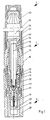
- the tube writing device shown in FIG. 1 has a tube writing tip 1, onto which a holder shaft 2 is screwed from behind and a sealing cap 3 is screwed on from the front.
- the tube pen tip 1 has a cylinder body 10, in the front end of which a writing tube 11 is inserted and which forms an inner bore 18 connected to the rear end of the writing tube 11.
- a drop weight to be described with a drop weight body consisting of two parts 20 and 22 and a cleaning wire 21 which extends into the writing tube 11.
- a conventional falling weight safety device 16 is inserted into the inner bore 18 from behind, which has a central bore 17 in its end wall.
- a helical groove 12 On the outer surface of the cylinder body 10 there is a helical groove 12, the rear end of which is connected to the inner bore 18 via a transverse bore 13 and the front end of which is connected to the ambient air, the groove 12 forming a pressure compensation chamber by means of a plugged in from the front Sleeve 14 is covered.
- a bushing element 15 is plugged onto the rear end of the cylinder body 10 from behind and connected to it by ultrasonic welding, which carries a writing fluid tank 24 at its rear end, which forms a writing fluid storage space 25. Furthermore, the shaft element 40 of the holder shaft 2 is screwed onto the socket part 15 from behind. In the front area, the socket element 15 has an external thread for fastening the main body 30 of the sealing cap 3, which carries an insert element 31, into which a sealing element 32 is inserted, which, when the sealing cap 3 is screwed on, lies sealingly against the front end of the writing tube 11 and in the area of the front end of the sleeve member 14 causes a seal.
- the drop weight body consists of two parts, a cup-shaped metal part 22, which has a central central opening in its bottom wall, and an essentially rod-shaped plastic part 20, which is offset at its front end and slightly clamped with this area in the metal part 22 is used.
- the cleaning wire 21 is fixed, which extends through the central opening of the metal part 22.
- the outer surface of the bottom wall of the metal part 22 in the position shown rests on ribs 23 provided in the inner bore 18 when the sealing cap 3 is removed and the writing tube 11 is not placed on a writing or drawing pad.
- This support of the surface of the metal part 22 which forms the front contact surface of the drop weight body thus determines the position of the cleaning wire 21 which is most forwardly displaced and thus its projection beyond the front end of the writing tube 11.
- the fitter can change this projection by changing the axial distance from the metal part 22 and Plastic part 20 changes, that is, the plastic part 20 either pushes further into the metal part 22 or pulls it out until the desired projection is reached. Thereafter, a permanent connection between the plastic part 20 and the metal part 22 can be made, for example, by adhesive, in order to reliably prevent relative axial displacements of these parts during operation and thus a change in the protrusion of the cleaning wire 21 over the front end of the writing tube 11.
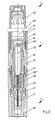
- the tube writing device is constructed essentially the same as that from FIG. 1, and the same parts are identified by the same reference symbols.
- the only deviation from the exemplary embodiment according to FIG. 1 consists in the structure of the drop weight, which has a rod-shaped part 20 ', in whose threaded end 20 ′′′ formed at its front end there is a cleaning wire 21'.
- the part 20 ' which consists for example of plastic, is screwed into a substantially cup-shaped part 22', for example made of metal, with the cleaning wire 21 'extending through a central opening in the bottom of the part 22'.
- On the rear end of the part 20 ' sits a hexagon head 20 ⁇ , so that the part 20' by holding the part 22 'and turning the hexagon head 20 ⁇ by means of a key further into the part 22' can be screwed in or out of this.
- the feasible relative axial adjustment of the parts 20 'and 22' makes it possible, in the manner described in connection with FIG. 1, to set the protrusion of the cleaning wire 21 'over the front end of the writing tube 11 to the desired value. If necessary, the parts 20 'and 22' can then be connected to one another in a non-rotatable manner.
Landscapes
- Pens And Brushes (AREA)
Applications Claiming Priority (2)
| Application Number | Priority Date | Filing Date | Title |
|---|---|---|---|
| DE19883815712 DE3815712C1 (fr) | 1988-05-07 | 1988-05-07 | |
| DE3815712 | 1988-05-07 |
Publications (1)
| Publication Number | Publication Date |
|---|---|
| EP0341484A1 true EP0341484A1 (fr) | 1989-11-15 |
Family
ID=6353924
Family Applications (1)
| Application Number | Title | Priority Date | Filing Date |
|---|---|---|---|
| EP89107441A Withdrawn EP0341484A1 (fr) | 1988-05-07 | 1989-04-25 | Dispositif de masselotte pour instrument d'écriture à tube |
Country Status (2)
| Country | Link |
|---|---|
| EP (1) | EP0341484A1 (fr) |
| DE (1) | DE3815712C1 (fr) |
Cited By (2)
| Publication number | Priority date | Publication date | Assignee | Title |
|---|---|---|---|---|
| US5000606A (en) * | 1988-05-07 | 1991-03-19 | Koh-I-Noor Rapidograph, Inc. | Drop-weight and tubular writing instrument |
| US5052841A (en) * | 1989-06-27 | 1991-10-01 | Koh-I-Noor Inc. | Stylo pen tip |
Citations (4)
| Publication number | Priority date | Publication date | Assignee | Title |
|---|---|---|---|---|
| US2217502A (en) * | 1940-04-04 | 1940-10-08 | Wallace Joseph | Stylorgraphic pen |
| DE744671C (de) * | 1941-12-03 | 1944-01-22 | Faber Castell A W | Fallgewicht aus tintenbestaendigem Werkstoff fuer die Schreibnadel von Fuellhaltern |
| FR986766A (fr) * | 1949-03-18 | 1951-08-06 | Perfectionnement aux stylographes | |
| DE3434188A1 (de) * | 1984-09-18 | 1986-03-27 | Rotring-Werke Riepe Kg, 2000 Hamburg | Roehrchenschreiberspitze |
Family Cites Families (2)
| Publication number | Priority date | Publication date | Assignee | Title |
|---|---|---|---|---|
| DE1984015U (de) * | 1964-08-07 | 1968-04-18 | Filler & Fiebig G M B H | Trichterfeder fuer zeichen- und schriftschablonen. |
| DE1611802C3 (de) * | 1968-01-11 | 1979-06-28 | Rotring-Werke Riepe Kg, 2000 Hamburg | Fallgewicht mit Reinigungsdraht für Röhrchenschreiber |
-
1988
- 1988-05-07 DE DE19883815712 patent/DE3815712C1/de not_active Expired
-
1989
- 1989-04-25 EP EP89107441A patent/EP0341484A1/fr not_active Withdrawn
Patent Citations (4)
| Publication number | Priority date | Publication date | Assignee | Title |
|---|---|---|---|---|
| US2217502A (en) * | 1940-04-04 | 1940-10-08 | Wallace Joseph | Stylorgraphic pen |
| DE744671C (de) * | 1941-12-03 | 1944-01-22 | Faber Castell A W | Fallgewicht aus tintenbestaendigem Werkstoff fuer die Schreibnadel von Fuellhaltern |
| FR986766A (fr) * | 1949-03-18 | 1951-08-06 | Perfectionnement aux stylographes | |
| DE3434188A1 (de) * | 1984-09-18 | 1986-03-27 | Rotring-Werke Riepe Kg, 2000 Hamburg | Roehrchenschreiberspitze |
Cited By (3)
| Publication number | Priority date | Publication date | Assignee | Title |
|---|---|---|---|---|
| US5000606A (en) * | 1988-05-07 | 1991-03-19 | Koh-I-Noor Rapidograph, Inc. | Drop-weight and tubular writing instrument |
| US5004365A (en) * | 1988-05-07 | 1991-04-02 | Koh-I-Noor Rapidograph, Inc. | Drop-weight and tubular writing instrument |
| US5052841A (en) * | 1989-06-27 | 1991-10-01 | Koh-I-Noor Inc. | Stylo pen tip |
Also Published As
| Publication number | Publication date |
|---|---|
| DE3815712C1 (fr) | 1989-11-23 |
Similar Documents
| Publication | Publication Date | Title |
|---|---|---|
| DE2718170C3 (de) | Befestigungsclip für verkleidete Abdeckplatten, insbesondere für Kraftfahrzeuge | |
| DE3426671C2 (fr) | ||
| DE3153217C2 (de) | Schreibgerät | |
| WO1998052657A1 (fr) | Tube reglable en longueur, notamment pour batons de ski ou cannes | |
| DE2030422C3 (de) | Gewinde-Einsatz | |
| DE3001414A1 (de) | Einzelteil-montageanordnung | |
| DE3005430C2 (de) | Schreibgeraet | |
| DE2751208C2 (de) | Luftleitungsanschluß | |
| DE2926575A1 (de) | Verbindungselement fuer optische fasern | |
| DE69303433T2 (de) | Drehlagerfeder für sonnenblende eines kraftfahrzeugs | |
| DE4137838C2 (de) | Schreibgerät | |
| EP0341484A1 (fr) | Dispositif de masselotte pour instrument d'écriture à tube | |
| DE10083312B4 (de) | Dichtungsvorrichtung | |
| DE3434188A1 (de) | Roehrchenschreiberspitze | |
| DE102006059096B4 (de) | Baugruppe zur fahrzeugseitigen Befestigung eines Gurtschlosses | |
| DE20207685U1 (de) | Halter | |
| DE2024854A1 (de) | Kunststoffverkleidungsteil für Zylinderkopfschrauben | |
| DE4234262A1 (de) | In einer Wand befestigter Verbinder mit selbsthaltendem Verbinderteil | |
| DE2620430C3 (de) | Feststellvorrichtung für ein Tiefbohrwerkzeug o.dgl. Bohrwerkzeug in einer Werkzeugmaschinenspindel | |
| DE8235498U1 (de) | Vorrichtung zur unverlierbaren Halterung einer Schraube | |
| EP1425189B1 (fr) | Capuchon destine a un instrument d'ecriture, de dessin ou de peinture | |
| DE9409743U1 (de) | Eckverbinder für Zargen | |
| EP0616903B1 (fr) | Capuchon pour instruments d'écriture | |
| DE19624054C2 (de) | Einrichtung zum Schnellaustausch einer Schweißelektrode | |
| DE2731096C3 (de) | Einrichtung zur Verlängerung einer Antriebswelle mit eckigem Querschnitt |
Legal Events
| Date | Code | Title | Description |
|---|---|---|---|
| PUAI | Public reference made under article 153(3) epc to a published international application that has entered the european phase |
Free format text: ORIGINAL CODE: 0009012 |
|
| AK | Designated contracting states |
Kind code of ref document: A1 Designated state(s): AT BE CH DE ES FR GB GR IT LI LU NL SE |
|
| 17P | Request for examination filed |
Effective date: 19891128 |
|
| 17Q | First examination report despatched |
Effective date: 19910524 |
|
| STAA | Information on the status of an ep patent application or granted ep patent |
Free format text: STATUS: THE APPLICATION IS DEEMED TO BE WITHDRAWN |
|
| 18D | Application deemed to be withdrawn |
Effective date: 19920604 |