EP0339327B1 - Einrichtung zum Fördern pastenartiger Massen - Google Patents
Einrichtung zum Fördern pastenartiger Massen Download PDFInfo
- Publication number
- EP0339327B1 EP0339327B1 EP89106101A EP89106101A EP0339327B1 EP 0339327 B1 EP0339327 B1 EP 0339327B1 EP 89106101 A EP89106101 A EP 89106101A EP 89106101 A EP89106101 A EP 89106101A EP 0339327 B1 EP0339327 B1 EP 0339327B1
- Authority
- EP
- European Patent Office
- Prior art keywords
- pump
- pump chamber
- housing
- wall
- filling
- Prior art date
- Legal status (The legal status is an assumption and is not a legal conclusion. Google has not performed a legal analysis and makes no representation as to the accuracy of the status listed.)
- Expired - Lifetime
Links
- 235000011837 pasties Nutrition 0.000 title abstract 2
- 235000013580 sausages Nutrition 0.000 claims abstract description 13
- 235000013372 meat Nutrition 0.000 claims abstract description 10
- 230000007704 transition Effects 0.000 claims description 6
- 238000007789 sealing Methods 0.000 claims description 2
- 230000009471 action Effects 0.000 abstract description 2
- 238000000034 method Methods 0.000 description 2
- 230000008569 process Effects 0.000 description 2
- 230000008901 benefit Effects 0.000 description 1
- 230000015572 biosynthetic process Effects 0.000 description 1
- 238000010276 construction Methods 0.000 description 1
- 230000002950 deficient Effects 0.000 description 1
- 239000000945 filler Substances 0.000 description 1
- 230000009969 flowable effect Effects 0.000 description 1
- 230000006872 improvement Effects 0.000 description 1
- 210000000936 intestine Anatomy 0.000 description 1
- 230000002093 peripheral effect Effects 0.000 description 1
- 230000000717 retained effect Effects 0.000 description 1
- 239000007787 solid Substances 0.000 description 1
Images
Classifications
-
- A—HUMAN NECESSITIES
- A22—BUTCHERING; MEAT TREATMENT; PROCESSING POULTRY OR FISH
- A22C—PROCESSING MEAT, POULTRY, OR FISH
- A22C11/00—Sausage making ; Apparatus for handling or conveying sausage products during manufacture
- A22C11/02—Sausage filling or stuffing machines
- A22C11/08—Sausage filling or stuffing machines with pressing-worm or other rotary-mounted pressing-members
-
- B—PERFORMING OPERATIONS; TRANSPORTING
- B65—CONVEYING; PACKING; STORING; HANDLING THIN OR FILAMENTARY MATERIAL
- B65G—TRANSPORT OR STORAGE DEVICES, e.g. CONVEYORS FOR LOADING OR TIPPING, SHOP CONVEYOR SYSTEMS OR PNEUMATIC TUBE CONVEYORS
- B65G53/00—Conveying materials in bulk through troughs, pipes or tubes by floating the materials or by flow of gas, liquid or foam
- B65G53/34—Details
- B65G53/40—Feeding or discharging devices
- B65G53/46—Gates or sluices, e.g. rotary wheels
- B65G53/4608—Turnable elements, e.g. rotary wheels with pockets or passages for material
- B65G53/4625—Turnable elements, e.g. rotary wheels with pockets or passages for material with axis of turning perpendicular to flow
- B65G53/4633—Turnable elements, e.g. rotary wheels with pockets or passages for material with axis of turning perpendicular to flow the element having pockets, rotated from charging position to discharging position, i.e. discrete flow
-
- F—MECHANICAL ENGINEERING; LIGHTING; HEATING; WEAPONS; BLASTING
- F01—MACHINES OR ENGINES IN GENERAL; ENGINE PLANTS IN GENERAL; STEAM ENGINES
- F01C—ROTARY-PISTON OR OSCILLATING-PISTON MACHINES OR ENGINES
- F01C21/00—Component parts, details or accessories not provided for in groups F01C1/00 - F01C20/00
- F01C21/10—Outer members for co-operation with rotary pistons; Casings
- F01C21/104—Stators; Members defining the outer boundaries of the working chamber
-
- F—MECHANICAL ENGINEERING; LIGHTING; HEATING; WEAPONS; BLASTING
- F04—POSITIVE - DISPLACEMENT MACHINES FOR LIQUIDS; PUMPS FOR LIQUIDS OR ELASTIC FLUIDS
- F04C—ROTARY-PISTON, OR OSCILLATING-PISTON, POSITIVE-DISPLACEMENT MACHINES FOR LIQUIDS; ROTARY-PISTON, OR OSCILLATING-PISTON, POSITIVE-DISPLACEMENT PUMPS
- F04C2/00—Rotary-piston machines or pumps
- F04C2/30—Rotary-piston machines or pumps having the characteristics covered by two or more groups F04C2/02, F04C2/08, F04C2/22, F04C2/24 or having the characteristics covered by one of these groups together with some other type of movement between co-operating members
- F04C2/34—Rotary-piston machines or pumps having the characteristics covered by two or more groups F04C2/02, F04C2/08, F04C2/22, F04C2/24 or having the characteristics covered by one of these groups together with some other type of movement between co-operating members having the movement defined in groups F04C2/08 or F04C2/22 and relative reciprocation between the co-operating members
- F04C2/344—Rotary-piston machines or pumps having the characteristics covered by two or more groups F04C2/02, F04C2/08, F04C2/22, F04C2/24 or having the characteristics covered by one of these groups together with some other type of movement between co-operating members having the movement defined in groups F04C2/08 or F04C2/22 and relative reciprocation between the co-operating members with vanes reciprocating with respect to the inner member
- F04C2/3441—Rotary-piston machines or pumps having the characteristics covered by two or more groups F04C2/02, F04C2/08, F04C2/22, F04C2/24 or having the characteristics covered by one of these groups together with some other type of movement between co-operating members having the movement defined in groups F04C2/08 or F04C2/22 and relative reciprocation between the co-operating members with vanes reciprocating with respect to the inner member the inner and outer member being in contact along one line or continuous surface substantially parallel to the axis of rotation
Definitions
- the invention relates to a vane pump for conveying paste-like masses, in particular sausage meat, for example for the purpose of producing portions of equal weight and / or volume, comprising a housing enclosing a pump chamber with an inlet and an outlet opening and a pump rotor which is driven in rotation in the housing and has radially displaceably guided plate-shaped slides , which are designed to slide against the axial boundary surfaces of the pump chamber and are kept in contact with the pump rotor with the radial inner wall of the pump chamber at least over part of their circulation.
- Vane pumps of this type are known in a variety of designs from the prior art.
- FR-A 2 205 119 in which an annular pump rotor provided with plate-shaped sliders is used, which is rotatably supported in an eccentric arrangement in a cylindrical housing.
- the slides are supported during their circulation on the one hand on the inner wall of the housing and on the other hand on a sleeve which is central to the housing and is arranged within the pump rotor.
- the supply and discharge openings are located opposite one another with a connection to the crescent-shaped pump chamber between said sleeve and the inner region of the annular pump rotor.
- This device which is used as a filler for filling sausage meat into intestines, has a pump rotor in the form of a driven hub which is eccentrically mounted in a housing and which is equipped with plate-shaped slides which are guided radially therein.
- the sliders are supported on the Inner wall of the housing and are held in contact with the inner wall in a channel curve machined into an axial end face thereof. While the inlet opening adjoins the visible pump chamber with axial alignment, the outlet opening is arranged tangentially.
- the concept mainly used in practice corresponds to the position of the inlet and outlet opening that of the device described last. Difficulties in achieving a full filling of the pump chamber, particularly with highly viscous and low-moisture sausages, are evident, which leads to the metering accuracy being unsatisfactory.
- the improvement in the degree of filling that can be achieved in this way is based, in particular, on the fact that this critical part of the pump chamber is designed in such a way that it is adapted to the radius-shaped flow front of a flowable mass that naturally results from the frictional conditions when it slides along a fixed wall.
- the vane pump is, for example, part of a filling device (not shown) for producing sausages and is driven in a suitable manner by a preferably controllable drive, also not shown, for example by a stepper motor.
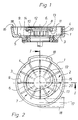
- the vane pump consists of a pump housing 1, which encloses a pump chamber 2 of cup-shaped shape with a bottom part 3 and a cylinder part 4 and can be closed by a cover, not shown, so that a cavity is formed in the shape of a cylinder disk.
- the transition region between the base part 3 and the cylinder part 4 is formed by a fillet 5.
- a pump rotor 6 is mounted to the cylinder part 4, which fills the pump chamber 2 between the cover and the base part 3 under a tight sliding fit with an essentially cylindrical hub part 7.
- the hub part 7 is provided with radial slots 8 running in the axial direction, in which plate-shaped sliders 9 are slidably guided with a slight sliding fit.
- the slider 9 are provided in the region of a stepped part 10 with a transverse groove 11, in which a control cam 12 engages. This is arranged in a recess 13 facing the cover of the pump housing 1 in the pump rotor 6 and is secured against rotation by means of suitable fixing means through the cover of the pump housing 1.
- the control curve 12 is designed as a cam disc and is delimited by a curve web 14 forming the periphery, which at the same time forms an inner curve 15.
- the controlling attack on the sliders 9 takes place, as mentioned above, by engagement of the curved web 14 in their respective groove 11.
- the pump housing 1 has an inlet opening 16 and an outlet opening 17 which are approximately diametrically opposed.
- the inlet opening 16 is designed as a pocket 18 in the cylinder part 4 of the pump housing 1 and is connected to a storage funnel built up on the cover thereof.
- the outlet opening 17 is located in an approximately tangentially attached to the pump housing 1 nozzle 19 and penetrates a wedge segment 20 arranged in the pump housing 1, which wedges in the cylinder part 4 in the region of the outlet opening 17 and in the direction of rotation of the pump rotor 6 in front of the latter.
- This wedge segment 20 begins practically cutting edge and ends with a contact surface on the cylinder part 4 of the pump rotor 6.
- the functional relationship is as follows: The mass stored in the storage hopper, not shown, for example sausage meat, is pushed towards its exit opening by a suitable stuffing device installed in the storage hopper. This process is supported in a known manner by the action of vacuum, to which the pump chamber 2 is subjected. These two measures cause the sausage meat to flow into the pocket 18 of the pump housing 1.
- a flow-shaped flow front is formed above all near solid wall parts, which is due to the fact that the friction between such wall parts and the sausage meat is generally greater than the internal friction in the sausage meat itself
- the sausage meat stream is retained on the wall of the cylinder part 4 of the pump housing 1 in relation to core areas of the flow cross section, so that such core areas hit the bottom part 3 first. Due to the formation of the transition area between this and the cylinder part 4 with the fillet 4, the overall cross section is also filled in this area at this moment without the flow front having to be deformed.
Landscapes
- Engineering & Computer Science (AREA)
- Mechanical Engineering (AREA)
- Life Sciences & Earth Sciences (AREA)
- General Engineering & Computer Science (AREA)
- Wood Science & Technology (AREA)
- Zoology (AREA)
- Food Science & Technology (AREA)
- Processing Of Meat And Fish (AREA)
- Rotary Pumps (AREA)
- Die Bonding (AREA)
- Apparatus For Radiation Diagnosis (AREA)
- Inorganic Insulating Materials (AREA)
Description
- Die Erfindung betrifft eine Flügelzellenpumpe zum Fördern pastenartiger Massen, insbesondere Wurstbrät, beispielsweise zwecks Erzeugung gewichts- und/oder volumengleicher Portionen, umfassend ein eine Pumpenkammer umschließendes Gehäuse mit einer Einlaß- und einer Auslaßöffnung und einen in dem Gehäuse rotierend angetriebenen Pumpenrotor mit radialverschiebbar geführten plattenförmigen Schiebern, welche an den axialen Begrenzungsflächen der Pumpenkammer gleitdichtend anliegend ausgeführt sind und zumindest über einen Teil ihres Umlaufes mit dem Pumpenrotor mit der radialen Innenwand der Pumpenkammer in Kontakt gehalten werden.
- Derartige Flügelzellenpumpen sind aus dem Stand der Technik in vielfältigen Ausführungen bekannt.
- So sei beispielhaft auf die FR-A 2 205 119 hingewiesen, bei welcher ein mit plattenförmigen Schiebern versehener, ringförmiger Pumpenrotor Anwendung findet, der unter exzentrischer Anordnung in einem zylindrischen Gehäuse umlaufend gelagert ist. Dabei stützen sich die Schieber während ihres Umlaufes einerseits an der Innenwand des Gehäuses und andererseits auf einer zu dem Gehäuse zentrischen, innerhalb des Pumpenrotors angeordneten Hülse ab. Zuführ- und Abgabeöffnung liegen sich mit Anschluß an die sichelförmige Pumpenkammer zwischen der genannten Hülse und dem Innenbereich des ringförmigen Pumpenrotors gegenüber.
- Aus der GB-A 1 056 529 ist eine Flügelzellenpumpe eines anderen Konzeptes bekannt. Diese als Füller zum Einfüllen von Wurstbrät in Därme verwendete Einrichtung weist einen in einem Gehäuse exzentrisch gelagerten Pumpenrotor in Form einer angetriebenen Nabe auf, welche mit in dieser radial geführten plattenförmigen Schiebern ausgestattet ist. Die Schieber stützen sich an der Innenwand des Gehäuses ab und werden in einer in eine axiale Abschlußfläche desselben eingearbeiteten Kanalkurve in Kontakt mit der Innenwand gehalten. Während die Einlaßöffnung unter axialer Ausrichtung an die sichtelförmige Pumpenkammer anschließt, ist die Auslaßöffnung tangential angeordnet.
- Das überwiegend in der Praxis zur Anwendung kommende Konzept entspricht bezüglich der Lage der Einlaß- und Auslaßöffnung dem der letztbeschriebenen Einrichtung. Dabei zeigen sich insbesondere bei hochviskosen und feuchtigkeitsarmen Brätsorten Schwierigkeiten, eine vollständige Füllung der Pumpenkammer zu erreichen, welcher Umstand dazu führt, daß die Dosiergenauigkeit unbefriedigend ist.
- Es ist die Aufgabe der Erfindung, den Füllungsgrad der Pumpenkammer zu verbessern.
- Die Lösung dieser Aufgabe macht sich die Erkenntnis zunutze, daß die mangelhafte Füllung vornehmlich in denjenigen Teilen der Pumpenkammer zu beobachten ist, die von der Einlaßöffnung am weitesten abgelegen sind. Das ist insbesondere der Übergangsbereich zwischen der der Einlaßöffnung gegenüberliegenden axialen Begrenzungsfläche der Pumpenkammer und der radialen Innenwand derselben, wobei sich als nachteilig auch zu erkennen gibt, daß dieser Übergangsbereich bauartbedingt durch Aneinandergrenzen fester Wände entsteht.
- Zur Verbesserung des Füllungsgrades wird daher vorgeschlagen, den genannten Übergangsbereich mit einer Hohlkehle auszubilden.
- Die damit erzielbare Verbesserung des Füllungsgrades beruht insbesondere darauf, daß dieser kritische Teil der Pumpenkammer eine Ausgestaltung erhält, die der sich natürlicherweise aufgrund der Reibungsverhältnisse ergebenden radiusförmigen Fließfront einer fließfähigen Masse angepaßt ist, wenn diese an einer feststehenden Wandung entlanggleitet.
- Die Erfindung wird nachstehend anhand eines in der Zeichnung dargestellten Ausführungsbeispiels näher erläutert. Es zeigt.
- Fig. 1 einen Querschnitt durch die Flügelzellenpumpe längs der Schnittlinie I-I,
- Fig. 2 eine Draufsicht auf die erfindungsgemäße Flügelzellenpumpe in vereinfachter Darstellung.
- Die Flügelzellenpumpe ist beispielsweise Bestandteil einer nicht dargestellten Fülleinrichtung zum Herstellen von Würsten und wird in geeigneter Weise durch einen ebenfalls nicht gezeigten, vorzugsweise steuerbaren Antrieb, beispielsweise durch einen Schrittmotor angetrieben. Die Flügelzellenpumpe besteht aus einem Pumpengehäuse 1, welches eine Pumpenkammer 2 von topfförmiger Gestalt mit einem Bodenteil 3 und einem Zylinderteil 4 umschließt und durch einen nicht gezeigten Deckel verschließbar ist, so daß ein Hohlraum von der Gestalt einer Zylinderscheibe entsteht. Der Übergangsbereich zwischen dem Bodenteil 3 und dem Zylinderteil 4 wird durch eine Hohlkehle 5 gebildet. In dem Bodenteil 3 des Pumpengehäuses 1 und konzentrisch zu dem Zylinderteil 4 ist ein Pumpenrotor 6 gelagert, der mit einem im wesentlichen zylindrischen Nabenteil 7 die Pumpenkammer 2 zwischen Deckel und Bodenteil 3 unter engem Gleitsitz ausfüllt. Das Nabenteil 7 ist mit in Achsrichtung verlaufenden Radialschlitzen 8 versehen, in welchen plattenförmige Schieber 9 unter leichtem Schiebesitz verschiebbar geführt sind. Die Schieber 9 sind im Bereich eines abgesetzten Teiles 10 mit einer quer verlaufenden Nut 11 versehen, in die eine Steuerkurve 12 eingreift. Diese ist in einer dem Deckel des Pumpengehäuses 1 zuweisenden Eindrehung 13 in dem Pumpenrotor 6 angeordnet und wird mittels geeigneter Fixiermittel verdrehsicher durch den Deckel des Pumpengehäuses 1 fixiert. Die Steuerkurve 12 ist als Kurvenscheibe gestaltet und von einem die Peripherie bildenden Kurvensteg 14 begrenzt, der gleichzeitig eine Innenkurve 15 bildet. Der steuernde Angriff an den Schiebern 9 erfolgt, wie oben erwähnt, durch Eingriff des Kurvensteges 14 in deren jeweilige Nut 11. Das Pumpengehäuse 1 weist eine Einlaßöffnung 16 und eine Auslaßöffnung 17 auf, die sich etwa diametral gegenüberstehen. Die Einlaßöffnung 16 ist dabei als Tasche 18 in dem Zylinderteil 4 des Pumpengehäuses 1 ausgebildet und steht mit einem sich auf dem Deckel desselben aufbauenden Vorratstrichter in Verbindung. Die Auslaßöffnung 17 befindet sich in einem etwa tangential an dem Pumpengehäuse 1 angebrachten Stutzen 19 und durchdringt ein in dem Pumpengehäuse 1 angeordnetes Keilsegment 20, welches sich in dem Zylinderteil 4 im Bereich der Auslaßöffnung 17 und in Drehrichtung des Pumpenrotors 6 vor dieser einschmiegt. Dabei beginnt dieses Keilsegment 20 praktisch schneidenförmig und endet mit einer Anlagefläche an dem Zylinderteil 4 des Pumpenrotors 6.
- Der funktionelle Zusammenhang ist folgender:
Die in dem nicht gezeigten Vorratstrichter bevorratete Masse, z.B. Wurstbrät, wird durch eine geeignete, in dem Vorratstrichter installierte Stopfeinrichtung in Richtung auf seine Ausgangsöffnung gedrängt. Unterstützt wird dieser Vorgang in bekannter Weise durch Einwirken von Vakuum, welchem die Pumpenkammer 2 unterworfen wird. Diese beiden Maßnahmen bewirken, daß das Wurstbrät in die Tasche 18 des Pumpengehäuses 1 einfließt. Insbesondere bei hochviskosen und feuchtigkeitsarmen Brätsorten bildet sich dabei eine vor allem in der Nähe fester Wandteile radiusförmige Fließfront aus, was seine Ursache darin hat, daß die Reibung zwischen solchen Wandteilen und dem Brät in der Regel größer ist, als die innere Reibung in dem Brät selbst. Infolgedessen wird der Brätstrom an der Wandung des Zylinderteils 4 des Pumpengehäuses 1 gegenüber Kernbereichen des Fließquerschnittes zurückgehalten, so daß solche Kernbereiche den Bodenteil 3 zuerst treffen. Aufgrund der Ausbildung des Übergangsbereiches zwischen diesem und dem Zylinderteil 4 mit der Hohlkehle 4 ist in diesem Augenblick der Gesamtquerschnitt auch in diesem Bereich gefüllt, ohne daß sich die Fließfront umformen muß. - Damit wird insbesondere bei den genannten schwierig verarbeitbaren Bratsorten eine für die Präzision der Dosierung entscheidende sicherere Füllung der Flügelzellenpumpe erreicht, was letzlich auch eine höhere Leistung zu fahren erlaubt.
- Der übrige Teil der Kammern zwischen den Schiebern 9 und dem Pumpenrotor 6 füllt sich problemlos, da die jeweiligen Stoßkanten der die Kammern begrenzenden Flächen relativ zueinander bewegt werden, so daß die jeweiligen Fließfronten leicht verformende Kräfte wirksam sind.
- Die gefüllten Kammern zwischen den Schiebern 9 verlagern sich nun aufgrund der Drehung des Pumpenrotors 6 in Richtung Auslaßöffnung 17, wobei die Schieber 9 nach und nach aus der Pumpenkammer 3 zurückgezogen werden, so daß sich die Kammern zwischen den Schiebern 9 zu der Auslaßöffnung 17 hin zunehmend vereinen. Kurz vor Erreichen des Keilsegmentes 20 sind die Schieber 9 schließlich soweit zurückgezogen, daß ihre vorher an der Innenwand des Zylinderteils 4 der Pumpenkammer 2 anliegenden, äußeren radialen Begrenzungskanten mit der Umfangsfläche des Pumpenrotors 6 bündig stehen und unter das Keilsegment 20 tauchen können.
- Damit wird das Brät insbesondere durch den vor Auslaßöffnung 17 letzten, gegenüber der Innenwand des Zylinderteils 4 dichtenden Schieber 9 der Auslaßöffnung 17 zugeschoben, wobei die durch den Rückzug der Schieber 9 entstehenden definierten Hohlräume aufgrund des dynamischen Gegendrucks in dem Abflußkanal aufgefüllt werden. Es ergibt sich ein pulsationsfreier Füllstrom, praktisch idealer Homogenität.
Claims (1)
Priority Applications (1)
| Application Number | Priority Date | Filing Date | Title |
|---|---|---|---|
| AT89106101T ATE70162T1 (de) | 1988-04-27 | 1989-04-07 | Einrichtung zum foerdern pastenartiger massen. |
Applications Claiming Priority (2)
| Application Number | Priority Date | Filing Date | Title |
|---|---|---|---|
| DE8805548U | 1988-04-27 | ||
| DE8805548U DE8805548U1 (de) | 1988-04-27 | 1988-04-27 | Einrichtung zum Fördern pastenartiger Massen |
Publications (2)
| Publication Number | Publication Date |
|---|---|
| EP0339327A1 EP0339327A1 (de) | 1989-11-02 |
| EP0339327B1 true EP0339327B1 (de) | 1991-12-11 |
Family
ID=6823413
Family Applications (1)
| Application Number | Title | Priority Date | Filing Date |
|---|---|---|---|
| EP89106101A Expired - Lifetime EP0339327B1 (de) | 1988-04-27 | 1989-04-07 | Einrichtung zum Fördern pastenartiger Massen |
Country Status (7)
| Country | Link |
|---|---|
| US (1) | US5069608A (de) |
| EP (1) | EP0339327B1 (de) |
| AT (1) | ATE70162T1 (de) |
| DD (1) | DD283765A5 (de) |
| DE (2) | DE8805548U1 (de) |
| ES (1) | ES2029090T3 (de) |
| RU (1) | RU1838666C (de) |
Families Citing this family (13)
| Publication number | Priority date | Publication date | Assignee | Title |
|---|---|---|---|---|
| DE3909137C1 (de) * | 1989-03-21 | 1990-05-10 | Nordischer Maschinenbau Rud. Baader Gmbh + Co Kg, 2400 Luebeck, De | |
| DE4227621A1 (de) * | 1992-08-20 | 1994-02-24 | Handtmann Albert Maschf | Verfahren und Vorrichtung zum portionsweisen Unterteilen einer pastösen und kompressiblen Masse, insbesondere eines Wurstbräts mit Hilfe einer Flügelzellenpumpe |
| US5366361A (en) * | 1992-09-04 | 1994-11-22 | Osaka Gas Co., Ltd. | Vane pump |
| DE9420306U1 (de) * | 1994-12-19 | 1995-02-16 | Albert Handtmann Maschinenfabrik GmbH & Co KG, 88400 Biberach | Flügelzellenpumpe |
| DE19914499C2 (de) * | 1999-03-30 | 2001-12-20 | Handtmann Albert Maschf | Fördervorrichtung für pastöse Massen und Verfahren zur Bestimmung deren Luftinhaltes |
| ATE363834T1 (de) * | 2004-02-10 | 2007-06-15 | Handtmann Albert Maschf | Vorrichtung und verfahren zum herstellen von würsten |
| US9188005B2 (en) * | 2007-10-18 | 2015-11-17 | Standex International Corporation | Sliding vane pump with internal cam ring |
| KR101220371B1 (ko) * | 2010-09-17 | 2013-01-09 | 현대자동차주식회사 | 베인펌프 |
| EP2628391B1 (de) * | 2012-02-15 | 2016-04-20 | Albert Handtmann Maschinenfabrik GmbH & Co. KG | Verfahren zum Füllen von Würsten mit pastöser Masse sowie Füllmaschine zum Durchführen dieses Verfahrens |
| EA033768B1 (ru) * | 2015-03-12 | 2019-11-22 | Machine Building Entpr Kompo Ltd | Устройство выравнивания давления продукта для шприца вакуумного |
| EA032193B1 (ru) * | 2015-03-12 | 2019-04-30 | Общество с ограниченной ответственностью "Машиностроительное предприятие "КОМПО" | Роторно-лопастной насос шприца вакуумного и сменная вставка для него |
| CN106672658B (zh) * | 2017-01-16 | 2022-07-12 | 高云 | 一种喷浆泵及其使用方法 |
| CN116420761B (zh) * | 2023-03-23 | 2025-01-24 | 天飨(山东)生物科技有限公司 | 用于制备具有虎皮纹路的肉肠的灌肠机 |
Family Cites Families (8)
| Publication number | Priority date | Publication date | Assignee | Title |
|---|---|---|---|---|
| US954832A (en) * | 1909-02-13 | 1910-04-12 | Charles A Carter | Rotary engine. |
| US1269937A (en) * | 1916-08-31 | 1918-06-18 | Glenn S Hardin | Internal-combustion engine. |
| US2837762A (en) * | 1953-11-12 | 1958-06-10 | Azzini Antonio | Rotary material press |
| US2963735A (en) * | 1956-10-25 | 1960-12-13 | Heinz Becker | Machines for introducing foodstuffs into containers |
| US2969935A (en) * | 1957-09-09 | 1961-01-31 | Carl C Price | Convertible aircraft |
| GB1203102A (en) * | 1967-05-06 | 1970-08-26 | Handtmann Albert Fa | A rotary pump assembly |
| ES397710A1 (es) * | 1970-12-15 | 1975-03-16 | Frigo | Perfeccionamientos en la construccion de electrocompresoresrotativos a paletas, en particular para avisadores acusti- cos. |
| IT999556B (it) * | 1972-10-30 | 1976-03-10 | Vemag Verdener Masch App | Pompa a celle a palette per il trasporto di ripieno di salumi |
-
1988
- 1988-04-27 DE DE8805548U patent/DE8805548U1/de not_active Expired
-
1989
- 1989-04-07 ES ES198989106101T patent/ES2029090T3/es not_active Expired - Lifetime
- 1989-04-07 AT AT89106101T patent/ATE70162T1/de not_active IP Right Cessation
- 1989-04-07 EP EP89106101A patent/EP0339327B1/de not_active Expired - Lifetime
- 1989-04-07 DE DE8989106101T patent/DE58900550D1/de not_active Expired - Lifetime
- 1989-04-25 DD DD89327949A patent/DD283765A5/de not_active IP Right Cessation
- 1989-04-26 US US07/343,283 patent/US5069608A/en not_active Expired - Fee Related
- 1989-04-27 RU SU894614066A patent/RU1838666C/ru active
Also Published As
| Publication number | Publication date |
|---|---|
| DE8805548U1 (de) | 1988-06-16 |
| RU1838666C (ru) | 1993-08-30 |
| DE58900550D1 (de) | 1992-01-23 |
| ATE70162T1 (de) | 1991-12-15 |
| DD283765A5 (de) | 1990-10-24 |
| ES2029090T3 (es) | 1992-07-16 |
| EP0339327A1 (de) | 1989-11-02 |
| US5069608A (en) | 1991-12-03 |
Similar Documents
| Publication | Publication Date | Title |
|---|---|---|
| EP0339327B1 (de) | Einrichtung zum Fördern pastenartiger Massen | |
| EP0432388B1 (de) | Flügelzellenpumpe zum Fördern von pasteusen Massen, insbesondere von Wurstbrät | |
| DE2326627C3 (de) | Hydraulische Flügelzellenpumpe | |
| EP0583721B1 (de) | Verfahren und Vorrichtung zum portionsweisen Unterteilen einer pastösen und kompressiblen Masse, insbesondere eines Wurstbräts mit Hilfe einer Flügelzellenpumpe | |
| DE68911828T2 (de) | Vorrichtung zum Strangpressen von Lebensmitteln. | |
| EP0718497A1 (de) | Flügelzellenpumpe | |
| DE3877016T2 (de) | Vorrichtung zum quantitativen extrudieren eines nahrungsmittels. | |
| EP0388625B1 (de) | Einrichtung zum Fördern von pastenartigen Massen | |
| DE1653921B2 (de) | Rotationskolbenpumpe | |
| DE4417161A1 (de) | Verdichter in Hypotrochoidenbauweise | |
| DE3518529C1 (de) | Vorrichtung zur Abgabe von pastosem Fuellgut in Portionen | |
| DE2421160C2 (de) | Rotationskolbenpumpe | |
| EP0370257A2 (de) | Ventil, insbesondere für manuelle Austragsvorrichtungen | |
| DE2121006C3 (de) | Verfahren und Vorrichtung zum Portionieren und Abdrehen einer pastenfönnigen Masse | |
| DE3901935C2 (de) | ||
| DE3219378C2 (de) | ||
| DE2533776A1 (de) | Drehmotor | |
| DE2248490C2 (de) | Drehkolbenpumpe | |
| DE3246421A1 (de) | Portioniereinrichtung fuer pastose massen | |
| CH663135A5 (de) | Vorrichtung zum ausbringen pastoser massen. | |
| DE3623739C2 (de) | Verbrennungsmotor | |
| DE2705571A1 (de) | Rotationskompressor | |
| DE2061385A1 (de) | Flügelzellenpumpe oder Flügelzellenmotor | |
| DE3537158A1 (de) | Verzahnte fluegelzellenpumpe | |
| DE4332192A1 (de) | Mischpistole für den Austrag verschiedener Medien |
Legal Events
| Date | Code | Title | Description |
|---|---|---|---|
| PUAI | Public reference made under article 153(3) epc to a published international application that has entered the european phase |
Free format text: ORIGINAL CODE: 0009012 |
|
| 17P | Request for examination filed |
Effective date: 19890824 |
|
| AK | Designated contracting states |
Kind code of ref document: A1 Designated state(s): AT BE CH DE ES FR GB IT LI LU NL SE |
|
| 17Q | First examination report despatched |
Effective date: 19910523 |
|
| GRAA | (expected) grant |
Free format text: ORIGINAL CODE: 0009210 |
|
| AK | Designated contracting states |
Kind code of ref document: B1 Designated state(s): AT BE CH DE ES FR GB IT LI LU NL SE |
|
| REF | Corresponds to: |
Ref document number: 70162 Country of ref document: AT Date of ref document: 19911215 Kind code of ref document: T |
|
| REF | Corresponds to: |
Ref document number: 58900550 Country of ref document: DE Date of ref document: 19920123 |
|
| ITF | It: translation for a ep patent filed | ||
| PGFP | Annual fee paid to national office [announced via postgrant information from national office to epo] |
Ref country code: BE Payment date: 19920220 Year of fee payment: 4 |
|
| ET | Fr: translation filed | ||
| PGFP | Annual fee paid to national office [announced via postgrant information from national office to epo] |
Ref country code: LU Payment date: 19920326 Year of fee payment: 4 |
|
| PGFP | Annual fee paid to national office [announced via postgrant information from national office to epo] |
Ref country code: SE Payment date: 19920402 Year of fee payment: 4 |
|
| GBT | Gb: translation of ep patent filed (gb section 77(6)(a)/1977) | ||
| PGFP | Annual fee paid to national office [announced via postgrant information from national office to epo] |
Ref country code: NL Payment date: 19920430 Year of fee payment: 4 |
|
| EPTA | Lu: last paid annual fee | ||
| PLBE | No opposition filed within time limit |
Free format text: ORIGINAL CODE: 0009261 |
|
| STAA | Information on the status of an ep patent application or granted ep patent |
Free format text: STATUS: NO OPPOSITION FILED WITHIN TIME LIMIT |
|
| 26N | No opposition filed | ||
| BECA | Be: change of holder's address |
Free format text: 921217 *NAHRUNGSGUETER MASCHINENBAU G.M.B.H.:WOLDEGKER STR. 35, 0-2000 NEUBRANDENBURG |
|
| REG | Reference to a national code |
Ref country code: GB Ref legal event code: 732E |
|
| REG | Reference to a national code |
Ref country code: CH Ref legal event code: PUE Owner name: NAHRUNGSGUETER MASCHINENBAU GMBH |
|
| REG | Reference to a national code |
Ref country code: FR Ref legal event code: TP |
|
| PG25 | Lapsed in a contracting state [announced via postgrant information from national office to epo] |
Ref country code: LU Free format text: LAPSE BECAUSE OF NON-PAYMENT OF DUE FEES Effective date: 19930407 Ref country code: GB Effective date: 19930407 |
|
| PG25 | Lapsed in a contracting state [announced via postgrant information from national office to epo] |
Ref country code: SE Effective date: 19930408 |
|
| PG25 | Lapsed in a contracting state [announced via postgrant information from national office to epo] |
Ref country code: BE Effective date: 19930430 |
|
| ITPR | It: changes in ownership of a european patent |
Owner name: CESSIONE;NAHRUNGS GUETER MASCHINENBAU GMBH |
|
| BERE | Be: lapsed |
Owner name: NAHRUNGSGUETER MASCHINENBAU G.M.B.H. Effective date: 19930430 |
|
| PG25 | Lapsed in a contracting state [announced via postgrant information from national office to epo] |
Ref country code: NL Effective date: 19931101 |
|
| NLS | Nl: assignments of ep-patents |
Owner name: NAHRUNGSGUETER MASCHINENBAU GMBH TE NEUBRANDENBURG |
|
| GBPC | Gb: european patent ceased through non-payment of renewal fee |
Effective date: 19930407 |
|
| NLV4 | Nl: lapsed or anulled due to non-payment of the annual fee | ||
| REG | Reference to a national code |
Ref country code: ES Ref legal event code: PC2A Owner name: NAHRUNGSGUTERMASCHINENBAU GMBH |
|
| EUG | Se: european patent has lapsed |
Ref document number: 89106101.2 Effective date: 19931110 |
|
| PGFP | Annual fee paid to national office [announced via postgrant information from national office to epo] |
Ref country code: CH Payment date: 19950301 Year of fee payment: 7 |
|
| PGFP | Annual fee paid to national office [announced via postgrant information from national office to epo] |
Ref country code: ES Payment date: 19950309 Year of fee payment: 7 |
|
| PGFP | Annual fee paid to national office [announced via postgrant information from national office to epo] |
Ref country code: FR Payment date: 19950320 Year of fee payment: 7 |
|
| PGFP | Annual fee paid to national office [announced via postgrant information from national office to epo] |
Ref country code: DE Payment date: 19950420 Year of fee payment: 7 |
|
| PGFP | Annual fee paid to national office [announced via postgrant information from national office to epo] |
Ref country code: AT Payment date: 19950817 Year of fee payment: 7 |
|
| PG25 | Lapsed in a contracting state [announced via postgrant information from national office to epo] |
Ref country code: AT Effective date: 19960407 |
|
| PG25 | Lapsed in a contracting state [announced via postgrant information from national office to epo] |
Ref country code: ES Free format text: LAPSE BECAUSE OF NON-PAYMENT OF DUE FEES Effective date: 19960408 |
|
| PG25 | Lapsed in a contracting state [announced via postgrant information from national office to epo] |
Ref country code: LI Effective date: 19960430 Ref country code: CH Effective date: 19960430 |
|
| REG | Reference to a national code |
Ref country code: CH Ref legal event code: PL |
|
| PG25 | Lapsed in a contracting state [announced via postgrant information from national office to epo] |
Ref country code: FR Effective date: 19961227 |
|
| PG25 | Lapsed in a contracting state [announced via postgrant information from national office to epo] |
Ref country code: DE Effective date: 19970101 |
|
| REG | Reference to a national code |
Ref country code: FR Ref legal event code: ST |
|
| REG | Reference to a national code |
Ref country code: ES Ref legal event code: FD2A Effective date: 19990405 |
|
| PG25 | Lapsed in a contracting state [announced via postgrant information from national office to epo] |
Ref country code: IT Free format text: LAPSE BECAUSE OF NON-PAYMENT OF DUE FEES;WARNING: LAPSES OF ITALIAN PATENTS WITH EFFECTIVE DATE BEFORE 2007 MAY HAVE OCCURRED AT ANY TIME BEFORE 2007. THE CORRECT EFFECTIVE DATE MAY BE DIFFERENT FROM THE ONE RECORDED. Effective date: 20050407 |