EP0338913A2 - Procédé de moulage par injection d'un substrat plastique pour un disque optique - Google Patents
Procédé de moulage par injection d'un substrat plastique pour un disque optique Download PDFInfo
- Publication number
- EP0338913A2 EP0338913A2 EP89401064A EP89401064A EP0338913A2 EP 0338913 A2 EP0338913 A2 EP 0338913A2 EP 89401064 A EP89401064 A EP 89401064A EP 89401064 A EP89401064 A EP 89401064A EP 0338913 A2 EP0338913 A2 EP 0338913A2
- Authority
- EP
- European Patent Office
- Prior art keywords
- molding cavity
- molding
- plastic substrate
- molten resin
- axial dimension
- Prior art date
- Legal status (The legal status is an assumption and is not a legal conclusion. Google has not performed a legal analysis and makes no representation as to the accuracy of the status listed.)
- Granted
Links
- 239000000758 substrate Substances 0.000 title claims abstract description 41
- 229920003023 plastic Polymers 0.000 title claims abstract description 22
- 238000001746 injection moulding Methods 0.000 title claims abstract description 14
- 230000003287 optical effect Effects 0.000 title claims description 7
- 239000004033 plastic Substances 0.000 title description 12
- 238000000465 moulding Methods 0.000 claims abstract description 45
- 229920005989 resin Polymers 0.000 claims abstract description 44
- 239000011347 resin Substances 0.000 claims abstract description 44
- 238000000034 method Methods 0.000 claims abstract description 16
- 230000008569 process Effects 0.000 claims abstract description 7
- 230000006872 improvement Effects 0.000 claims abstract description 5
- 239000004417 polycarbonate Substances 0.000 claims description 3
- 229920000515 polycarbonate Polymers 0.000 claims description 3
- 238000002347 injection Methods 0.000 description 9
- 239000007924 injection Substances 0.000 description 9
- 239000002991 molded plastic Substances 0.000 description 6
- 229920005668 polycarbonate resin Polymers 0.000 description 5
- 239000004431 polycarbonate resin Substances 0.000 description 5
- 238000001816 cooling Methods 0.000 description 4
- 238000006073 displacement reaction Methods 0.000 description 4
- 238000000748 compression moulding Methods 0.000 description 3
- 230000009477 glass transition Effects 0.000 description 3
- PXHVJJICTQNCMI-UHFFFAOYSA-N Nickel Chemical compound [Ni] PXHVJJICTQNCMI-UHFFFAOYSA-N 0.000 description 2
- 239000000969 carrier Substances 0.000 description 2
- 230000007423 decrease Effects 0.000 description 2
- 230000003247 decreasing effect Effects 0.000 description 2
- CPBQJMYROZQQJC-UHFFFAOYSA-N helium neon Chemical compound [He].[Ne] CPBQJMYROZQQJC-UHFFFAOYSA-N 0.000 description 2
- IEEZXCFWEVKMQT-UHFFFAOYSA-N 4-(1-phenylpropyl)phenol Chemical compound C=1C=C(O)C=CC=1C(CC)C1=CC=CC=C1 IEEZXCFWEVKMQT-UHFFFAOYSA-N 0.000 description 1
- 230000008901 benefit Effects 0.000 description 1
- 230000008859 change Effects 0.000 description 1
- 238000009826 distribution Methods 0.000 description 1
- 238000002474 experimental method Methods 0.000 description 1
- 238000003698 laser cutting Methods 0.000 description 1
- 229910052759 nickel Inorganic materials 0.000 description 1
- 238000009828 non-uniform distribution Methods 0.000 description 1
- 230000009467 reduction Effects 0.000 description 1
- 238000007711 solidification Methods 0.000 description 1
- 230000008023 solidification Effects 0.000 description 1
- 229920005992 thermoplastic resin Polymers 0.000 description 1
Images
Classifications
-
- B—PERFORMING OPERATIONS; TRANSPORTING
- B29—WORKING OF PLASTICS; WORKING OF SUBSTANCES IN A PLASTIC STATE IN GENERAL
- B29C—SHAPING OR JOINING OF PLASTICS; SHAPING OF MATERIAL IN A PLASTIC STATE, NOT OTHERWISE PROVIDED FOR; AFTER-TREATMENT OF THE SHAPED PRODUCTS, e.g. REPAIRING
- B29C45/00—Injection moulding, i.e. forcing the required volume of moulding material through a nozzle into a closed mould; Apparatus therefor
- B29C45/17—Component parts, details or accessories; Auxiliary operations
- B29C45/26—Moulds
- B29C45/263—Moulds with mould wall parts provided with fine grooves or impressions, e.g. for record discs
-
- B—PERFORMING OPERATIONS; TRANSPORTING
- B29—WORKING OF PLASTICS; WORKING OF SUBSTANCES IN A PLASTIC STATE IN GENERAL
- B29C—SHAPING OR JOINING OF PLASTICS; SHAPING OF MATERIAL IN A PLASTIC STATE, NOT OTHERWISE PROVIDED FOR; AFTER-TREATMENT OF THE SHAPED PRODUCTS, e.g. REPAIRING
- B29C45/00—Injection moulding, i.e. forcing the required volume of moulding material through a nozzle into a closed mould; Apparatus therefor
- B29C45/17—Component parts, details or accessories; Auxiliary operations
- B29C45/46—Means for plasticising or homogenising the moulding material or forcing it into the mould
- B29C45/56—Means for plasticising or homogenising the moulding material or forcing it into the mould using mould parts movable during or after injection, e.g. injection-compression moulding
Definitions
- the present invention relates to method for injection-molding a plastic substrate used in high-density information recording carriers or media such as optical disks, optical cards, optical tapes or the like. More particularly, it relates to an improvement in an injection-molding process for molding a transparent plastic substrate for DRAW type and Magneto-optical type recording disks.
- the high-density information recording carriers or media such as magneto-optical recording disks in which information is recorded in a form of spots each having a diameter of sub-micron order by a laser beam which passes through the plastic substrate and is focused on a recording layer supported on the plastic substrate, it is requested to reduce the birefringence in the transparent plastic substrates.
- the transparent plastic substrate is advantageously produced from injection-molded polycarbonate resin because of low cost and low moisture absorbing property thereof.
- the substrate made of polycarbonate resin shows rather high birefringence values.
- injection-compression molding technique In order to lower the birefringence of polycarbonate substrates, injection-compression molding technique is usually used (Japanese patent laid-open No. 62-9,926). Although this technique is very effective to reduce the birefringence, the conventional injection compression molding technique has such a problem that a fine concave-convex pattern consisting of formatting pits and/or trucking guide grooves engraved on a surface of a stamper by a laser cutting technique is difficult to be transferred precisely onto a surface of the plastic substrate.
- the present applicant proposed improved injection-molding processes for lowering remarkably the birefringence in co-pending Japanese patent application No. 61-45,900 and No. 61-80,189.
- the present invention was completed in the same line as these patent applications.
- An object of the present invention is to provide an improved process for injection-molding a plastic substrate, particularly a substrate made of polycarbonate resin, used in high-density information recording media
- the present invention provides an improved process for molding a transparent plastic substrate for a high-density information recording-reading system by injecting molten resin into a molding cavity defined by a pair of mold halves, characterized in that an axial dimension of the molding cavity is increased at least two times between the start of a shot of the molten resin and the end of the pressure-holding stage in an injection molding cycle.
- the pressure-holding stage means that mold clamping force and/or resin pressure are active in an injection molding cycle.
- the increment along the axial dimension of the molding cavity of at least two times is preferably effected within three seconds counting from the start of a shot.
- the total increment along the axial dimension of the molding cavity is preferably less than 1/10 of an axial dimension of the molding cavity.
- the present invention is advantageously applicable to polycarbonate resin but is also applicable to any other thermoplastic resins which same have problems in birefringence, pattern transfering property and/or dimensional stability.
- the essence of the present invention reside in such a finding that the control or adjustment along the axial dimension of the molding cavity is a critical factor in order to solve the above-mentioned problems, so that the other factors or conditions such as a cylinder temperature, a mold temperature or the like can be selected within the ordinary ranges which are adopted by the persons skilled in the art. Still more, the other operational conditions that have direct relations to the process of the present invention such as an injection pressure, a holding pressure, a mold clamping pressure and a mold cooling rate depend on the size and type of an injection molding machine used. The persons skilled in the art can easily find the optimum operational conditions by experiments.
- the birefringence may be caused mainly (1) by molecular orientation due to poor fluidity of polycarbonate and (2) by residual stress along an angular direction owing to shrinkage along the radial direction which occur in a cooling stage of resin.
- Transferring property is defined by an ability or quality to transfer a concave-convex pattern engraved on a surface of the stamper onto a surface of the molded plastic disk. This transfering property may depend on temperatures of the stamper and the mold by which the molding cavity is defined as well as temperature, pressure and residence time in the molding cavity of molten resin.
- Deformation of the molded plastic substrate is caused by non-uniform distribution of shrinkage.
- the molded plastic substrate bends like a saucer when an radially inner periphery of the substrate shrinks much larger than an radially outer periphery thereof, and the molded plastic substrate is twisted like a propeller when radially outer periphery of the substrate shrinks much larger than radially inner periphery.
- the present invention is effected just after the molten resin is injected into a molding cavity.
- the transfering property can be improved by increasing the pressure of molten resin in the molding cavity provided that the temperatures of stamper, mold and molten resin are kept at constant values.
- This transfering property is determined in a very short time after the molten resin is injected in the molding cavity. In fact, when the molten resin entered the molding cavity, the molten resin arrived at a surface of the stamper whose temperature is lower than the molten resin which is cooled to be solidified almost spontaneously, because the molding cavity is a very narrow flat space.
- the pressure of molten resin in an injection cylinder is elevated or increased firstly to a predetermined value while the primary mold clamping force is kept at a constant value.
- the pressure of resin in the molding cavity is equilibrated with the mold clamping force or the pressure of resin in the molding cavity becomes higher than the mold clamping force, resulting in that a movable mold half is forced to move along an axial direction so that a dimension of clearance of the molding cavity increases.
- the primary mold clamping force is selected to such a value as is necessary to transfer satisfactorily the embossed pattern of the stamper onto the substrate surface, while the resin pressure in the cavity is maintained at least for such a time duration as the embossed pattern can be transferred onto the substrate.
- the mold clamping force is dropped sharply in such a manner that the resin pressure in the molding cavity becomes higher than the mold clamping force. This results in that the movable mold half is forced to move along the axial direction, so that the the axial dimension of the molding cavity increases again.
- the mold clamping force is adjusted to a suitable lower value which can close the molding cavity in order to eliminate a residual stress.
- the resin in the molding cavity is cooled to shrink and have a reduced resin pressure, so that the axial dimension of the molding cavity decreases.
- the transfering property is little influenced by this final stage since the resin in the molding cavity already became cold.
- Deformation such as bend or twist of the molded plastic substrate is caused by difference in shrinkage between an inner periphery and an outer periphery of the substrate.
- it is proposed to differentiate temperatures at respective mold halves.
- the deformation can be eliminated by the above-mentioned increment of the axial dimension caused by the decrement of resin pressure which is effected after the second stage.
- the increment of the axial dimension according to the present invention is effective to make the distribution of resin pressure much uniform so that the deformation of the substrate is eliminated.
- the birefringence is caused mainly by molecular orientation and by residual stress. It is said that the molecular orientation occurs generally in an injection stage for filling the molding cavity with molten resin.
- the birefringence caused by the molecular orientation can be cancelled by the birefringence caused by the residual stress.
- such off-set of two birefringences can be effected by the above-mentioned increment of the axial dimension caused by the decrement of resin pressure which is effected after the second stage, so that the molecular orientation caused by resin flow or shear stress when the molten resin temperature is a little higher than its glass transition temperature is controlled.
- plastic substrates for optical disks produced by the injection process according to the present invention have improved properties which satisfy the three requirements of low birefringence, high pattern transfering property and high dimensional stability simultaneously.
- the present invention can be carried out in the conventional molding machine only by modifying the control conditions thereof.
- polycarbonate resin prepared from 2, 2-bis(4-hydroxydiphenyl)propane having an average molecular weight of 15,000 was used in an injection molding machine ("Dimamelter” manufactured by MEIKI Seisakusho, M-70).
- a molding cavity had a dimension of 300 mm in diameter and 1.2 mm in thickness.
- the injection molding machine was adjusted to a cylinder temperature of 360°C and a mold temperature of 120°C.
- Molten resin is injected from the cylinder into the molding cavity in such manner that a shot required 0.7 second. After then, the resin pressure in the cylinder was kept at 510 kgf/cm2 for 0.4 second and then was decreased to 70 kgf/cm2 for 0.6 second.
- the mold clamping force was set at 190 ton before the shot after 1.7 seconds from the start of the shot, the mold clamping force was dropped sharply down to 35 ton.
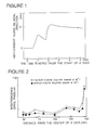
- Fig. 1 illustrates the time dependency of the axial displacement of the mold measured at a parting line of the mold. This figure shows such a fact that an axial dimension or clearance of the molding cavity increased or enlarged two times within 3 seconds counting from the start of the short. It is apparent that the amount of the axial displacement of the mold corresponds to the amount of the axial dimension or clearance of the molding cavity.
- the molded plastic disk was removed out of the mold after 20 second counting from the end of the shot.
- the values of birefringence was determined by passing a linearly polarized helium-neon laser (wave length of 6,328 ⁇ ) through the plastic disk substrate obtained. The result is shown in Fig. 2 (the values of birefringence are expressed by absolute values). It is apparent that the substrate obtained according to the present invention possesses a very low birefringence value.
- the substrate obtained showed no deformation such as bend or twist and has a surface of embossed trucking grooves which were well-transferred from the stamper.
Landscapes
- Engineering & Computer Science (AREA)
- Manufacturing & Machinery (AREA)
- Mechanical Engineering (AREA)
- Injection Moulding Of Plastics Or The Like (AREA)
- Manufacturing Optical Record Carriers (AREA)
- Moulds For Moulding Plastics Or The Like (AREA)
Applications Claiming Priority (2)
| Application Number | Priority Date | Filing Date | Title |
|---|---|---|---|
| JP63094782A JPH078514B2 (ja) | 1988-04-18 | 1988-04-18 | 光ディスク用プラスチック基板の射出成形法 |
| JP94782/88 | 1988-04-18 |
Publications (3)
| Publication Number | Publication Date |
|---|---|
| EP0338913A2 true EP0338913A2 (fr) | 1989-10-25 |
| EP0338913A3 EP0338913A3 (en) | 1990-06-13 |
| EP0338913B1 EP0338913B1 (fr) | 1994-08-10 |
Family
ID=14119657
Family Applications (1)
| Application Number | Title | Priority Date | Filing Date |
|---|---|---|---|
| EP89401064A Expired - Lifetime EP0338913B1 (fr) | 1988-04-18 | 1989-04-18 | Procédé de moulage par injection d'un substrat plastique pour un disque optique |
Country Status (4)
| Country | Link |
|---|---|
| US (1) | US5002706A (fr) |
| EP (1) | EP0338913B1 (fr) |
| JP (1) | JPH078514B2 (fr) |
| DE (1) | DE68917355T2 (fr) |
Cited By (2)
| Publication number | Priority date | Publication date | Assignee | Title |
|---|---|---|---|---|
| EP0612069A3 (fr) * | 1993-02-16 | 1994-11-17 | Canon Kk | Disque magnéto-optique. |
| WO1997027584A3 (fr) * | 1996-01-23 | 2001-09-13 | Nimbus Mfg Uk Ltd | Fabrication d'un disque optique de stockage de donnees |
Families Citing this family (15)
| Publication number | Priority date | Publication date | Assignee | Title |
|---|---|---|---|---|
| US6517755B1 (en) | 1919-07-18 | 2003-02-11 | Ube Industries, Ltd. | Resin multilayer molding method and mulitlayer molding device |
| JP2906349B2 (ja) * | 1989-11-01 | 1999-06-21 | 住友重機械工業株式会社 | 光ディスク基板の製造方法 |
| CA2130925C (fr) * | 1992-12-27 | 2002-06-11 | Seiichi Yamazaki | Piece moulee par insertion, appareil et procede de fabrication connexes |
| JP2597529B2 (ja) * | 1993-08-20 | 1997-04-09 | 日精樹脂工業株式会社 | 射出成形方法 |
| JP3343628B2 (ja) * | 1993-08-27 | 2002-11-11 | 日本ジーイープラスチックス株式会社 | 薄肉成形方法 |
| JP2787651B2 (ja) * | 1994-03-22 | 1998-08-20 | 日精樹脂工業株式会社 | 射出成形機の成形方法 |
| US5683630A (en) * | 1994-06-20 | 1997-11-04 | Matsushita Electric Industrial Co., Ltd. | Process for making optical disk substrates |
| US5547619A (en) * | 1994-09-30 | 1996-08-20 | The Japan Steel Works, Ltd. | Toggle type injection molding process |
| JP3519511B2 (ja) * | 1995-07-27 | 2004-04-19 | ファナック株式会社 | 射出成形機の制御方法および装置 |
| JPH09123203A (ja) * | 1995-11-01 | 1997-05-13 | Meiki Co Ltd | ディスク基板の成形方法およびその装置 |
| US6413461B1 (en) * | 1998-05-08 | 2002-07-02 | Sumitomo Chemical Company, Limited | Process for producing multilayer molded article |
| US7179551B2 (en) | 1999-02-12 | 2007-02-20 | General Electric Company | Poly(arylene ether) data storage media |
| KR100755089B1 (ko) | 1999-02-12 | 2007-09-03 | 제너럴 일렉트릭 캄파니 | 저장 매체, 기판 제조 방법, 데이터 검색 방법, 엠보싱 방법 및 데이터 저장 매체 형성 방법 |
| NL1015140C2 (nl) * | 2000-05-09 | 2001-11-13 | Otb Group Bv | Werkwijze en inrichting voor het spuitgieten van een kunststof voorwerp. |
| WO2002085537A2 (fr) * | 2001-04-19 | 2002-10-31 | General Electric Company | Support revetu par centrifugation |
Family Cites Families (9)
| Publication number | Priority date | Publication date | Assignee | Title |
|---|---|---|---|---|
| DE3028947C2 (de) * | 1980-07-30 | 1983-11-17 | Polygram Gmbh, 2000 Hamburg | Verfahren zur Herstellung plattenförmiger, optisch auslesbarer Informationsträger hoher Speicherdichte |
| JPS6195919A (ja) * | 1984-10-18 | 1986-05-14 | Sony Corp | 射出成形機 |
| JPS61177222A (ja) * | 1985-02-04 | 1986-08-08 | Meiki Co Ltd | 射出成形機による薄肉レンズの成形方法 |
| JPS61199919A (ja) * | 1985-02-28 | 1986-09-04 | Hishiya Seiko Kk | 射出成形機の射出工程制御方法 |
| JPS61205112A (ja) * | 1985-03-08 | 1986-09-11 | Idemitsu Petrochem Co Ltd | 射出圧縮成形方法 |
| JPS629926A (ja) * | 1985-07-09 | 1987-01-17 | Hitachi Ltd | 光デイスク基板成形方法 |
| JPS62204451A (ja) * | 1986-03-03 | 1987-09-09 | Daicel Chem Ind Ltd | 光デイスク用プラスチツク基板とその製法 |
| JPH07121544B2 (ja) * | 1986-07-31 | 1995-12-25 | キヤノン株式会社 | 光デイスク基板の製造法 |
| JPH0675888B2 (ja) * | 1986-11-28 | 1994-09-28 | ソニー株式会社 | デイスクの射出成形方法 |
-
1988
- 1988-04-18 JP JP63094782A patent/JPH078514B2/ja not_active Expired - Lifetime
-
1989
- 1989-04-18 DE DE68917355T patent/DE68917355T2/de not_active Expired - Fee Related
- 1989-04-18 US US07/339,777 patent/US5002706A/en not_active Expired - Fee Related
- 1989-04-18 EP EP89401064A patent/EP0338913B1/fr not_active Expired - Lifetime
Cited By (3)
| Publication number | Priority date | Publication date | Assignee | Title |
|---|---|---|---|---|
| EP0612069A3 (fr) * | 1993-02-16 | 1994-11-17 | Canon Kk | Disque magnéto-optique. |
| US5589244A (en) * | 1993-02-16 | 1996-12-31 | Canon Kabushiki Kaisha | Magneto-optical disc |
| WO1997027584A3 (fr) * | 1996-01-23 | 2001-09-13 | Nimbus Mfg Uk Ltd | Fabrication d'un disque optique de stockage de donnees |
Also Published As
| Publication number | Publication date |
|---|---|
| EP0338913B1 (fr) | 1994-08-10 |
| EP0338913A3 (en) | 1990-06-13 |
| US5002706A (en) | 1991-03-26 |
| DE68917355T2 (de) | 1995-05-18 |
| DE68917355D1 (de) | 1994-09-15 |
| JPH078514B2 (ja) | 1995-02-01 |
| JPH01264817A (ja) | 1989-10-23 |
Similar Documents
| Publication | Publication Date | Title |
|---|---|---|
| US5002706A (en) | Injection molding process of a plastic substrate for an optical disk | |
| EP0235800B1 (fr) | Substrat plastique pour disque optique et procédé pour sa fabrication | |
| EP0369781A2 (fr) | Procédé et dispositif de fabrication d'un substrat pour disque optique | |
| EP0137246B1 (fr) | Moule et matrice métalliques pour le moulage par injection d'un disque en matière plastique porteur d'informations à densité élevée | |
| US4879082A (en) | Method for molding plastic material into disk shaped sabstrate for an optical information record carrier | |
| JP3153116B2 (ja) | 貼り合わせディスク用基板の成形用金型 | |
| EP0864411B1 (fr) | Moule pour fabriquer des objets en forme de disque | |
| US5705105A (en) | Process for making optical disk substrates | |
| EP0338906B1 (fr) | Procédé de moulage d'un substrat formaté pour disque optique et moule pour la mise en oeuvre du procédé | |
| US5171585A (en) | Apparatus for molding a formatted substrate for an optical disk | |
| US20020067688A1 (en) | Optical disc and mold for manufacturing the optical disc | |
| EP1192034B1 (fr) | Procede de moulage de disques optiques avec une l'epaississement du bord reduit | |
| EP0444367B1 (fr) | Etampe pour un moule d'injection | |
| EP0276897B1 (fr) | Procédé de fabrication d'un substrat pour disque optique par un recuit d'un substrat ayant une distribution de gradient de double réfraction | |
| EP0390564B1 (fr) | Un moule en métal pour un substrat en résine pour un support d'enregistrement optique et support d'enregistrement obtenu par lemême | |
| US5906775A (en) | Method of producing substrate for optical disc | |
| JP2610558B2 (ja) | ディスク用基板成形法 | |
| JPH0367851B2 (fr) | ||
| JPH0751300B2 (ja) | プリフォーマット入り光ディスク基板の成形方法およびそれに用いる金型 | |
| JPH01264816A (ja) | フォーマット入り光ディスク基板の成形方法 | |
| JPH0763991B2 (ja) | フォーマット入り光ディスク基板成形用金型 | |
| JP2000293891A (ja) | 光ディスク基板及び光ディスク基板の成形金型 | |
| JPH09109197A (ja) | 光ディスク基板の製造法 | |
| JPH01160620A (ja) | 光ディスク基板の製造方法 | |
| JP2002210784A (ja) | 光ディスク基板成形用金型および光ディスク基板の製造方法 |
Legal Events
| Date | Code | Title | Description |
|---|---|---|---|
| PUAI | Public reference made under article 153(3) epc to a published international application that has entered the european phase |
Free format text: ORIGINAL CODE: 0009012 |
|
| AK | Designated contracting states |
Kind code of ref document: A2 Designated state(s): DE FR GB NL |
|
| PUAL | Search report despatched |
Free format text: ORIGINAL CODE: 0009013 |
|
| AK | Designated contracting states |
Kind code of ref document: A3 Designated state(s): DE FR GB NL |
|
| 17P | Request for examination filed |
Effective date: 19901206 |
|
| 17Q | First examination report despatched |
Effective date: 19920615 |
|
| GRAA | (expected) grant |
Free format text: ORIGINAL CODE: 0009210 |
|
| AK | Designated contracting states |
Kind code of ref document: B1 Designated state(s): DE FR GB NL |
|
| REF | Corresponds to: |
Ref document number: 68917355 Country of ref document: DE Date of ref document: 19940915 |
|
| ET | Fr: translation filed | ||
| PLBE | No opposition filed within time limit |
Free format text: ORIGINAL CODE: 0009261 |
|
| STAA | Information on the status of an ep patent application or granted ep patent |
Free format text: STATUS: NO OPPOSITION FILED WITHIN TIME LIMIT |
|
| 26N | No opposition filed | ||
| PGFP | Annual fee paid to national office [announced via postgrant information from national office to epo] |
Ref country code: FR Payment date: 19990409 Year of fee payment: 11 |
|
| PGFP | Annual fee paid to national office [announced via postgrant information from national office to epo] |
Ref country code: GB Payment date: 19990421 Year of fee payment: 11 |
|
| PGFP | Annual fee paid to national office [announced via postgrant information from national office to epo] |
Ref country code: NL Payment date: 19990426 Year of fee payment: 11 Ref country code: DE Payment date: 19990426 Year of fee payment: 11 |
|
| PG25 | Lapsed in a contracting state [announced via postgrant information from national office to epo] |
Ref country code: GB Free format text: LAPSE BECAUSE OF NON-PAYMENT OF DUE FEES Effective date: 20000418 |
|
| PG25 | Lapsed in a contracting state [announced via postgrant information from national office to epo] |
Ref country code: NL Free format text: LAPSE BECAUSE OF NON-PAYMENT OF DUE FEES Effective date: 20001101 |
|
| GBPC | Gb: european patent ceased through non-payment of renewal fee |
Effective date: 20000418 |
|
| PG25 | Lapsed in a contracting state [announced via postgrant information from national office to epo] |
Ref country code: FR Free format text: LAPSE BECAUSE OF NON-PAYMENT OF DUE FEES Effective date: 20001229 |
|
| NLV4 | Nl: lapsed or anulled due to non-payment of the annual fee |
Effective date: 20001101 |
|
| PG25 | Lapsed in a contracting state [announced via postgrant information from national office to epo] |
Ref country code: DE Free format text: LAPSE BECAUSE OF NON-PAYMENT OF DUE FEES Effective date: 20010201 |
|
| REG | Reference to a national code |
Ref country code: FR Ref legal event code: ST |