EP0338197A1 - Portioniereinheit für eine Füllanlage zum Füllen von Konservendosen - Google Patents
Portioniereinheit für eine Füllanlage zum Füllen von Konservendosen Download PDFInfo
- Publication number
- EP0338197A1 EP0338197A1 EP89101846A EP89101846A EP0338197A1 EP 0338197 A1 EP0338197 A1 EP 0338197A1 EP 89101846 A EP89101846 A EP 89101846A EP 89101846 A EP89101846 A EP 89101846A EP 0338197 A1 EP0338197 A1 EP 0338197A1
- Authority
- EP
- European Patent Office
- Prior art keywords
- hole
- filling
- filling material
- ring
- sealing plate
- Prior art date
- Legal status (The legal status is an assumption and is not a legal conclusion. Google has not performed a legal analysis and makes no representation as to the accuracy of the status listed.)
- Withdrawn
Links
Images


Classifications
-
- B—PERFORMING OPERATIONS; TRANSPORTING
- B65—CONVEYING; PACKING; STORING; HANDLING THIN OR FILAMENTARY MATERIAL
- B65B—MACHINES, APPARATUS OR DEVICES FOR, OR METHODS OF, PACKAGING ARTICLES OR MATERIALS; UNPACKING
- B65B3/00—Packaging plastic material, semiliquids, liquids or mixed solids and liquids, in individual containers or receptacles, e.g. bags, sacks, boxes, cartons, cans, or jars
- B65B3/26—Methods or devices for controlling the quantity of the material fed or filled
- B65B3/30—Methods or devices for controlling the quantity of the material fed or filled by volumetric measurement
- B65B3/32—Methods or devices for controlling the quantity of the material fed or filled by volumetric measurement by pistons co-operating with measuring chambers
- B65B3/323—Methods or devices for controlling the quantity of the material fed or filled by volumetric measurement by pistons co-operating with measuring chambers with measuring chambers travelling in an endless path
-
- F—MECHANICAL ENGINEERING; LIGHTING; HEATING; WEAPONS; BLASTING
- F16—ENGINEERING ELEMENTS AND UNITS; GENERAL MEASURES FOR PRODUCING AND MAINTAINING EFFECTIVE FUNCTIONING OF MACHINES OR INSTALLATIONS; THERMAL INSULATION IN GENERAL
- F16L—PIPES; JOINTS OR FITTINGS FOR PIPES; SUPPORTS FOR PIPES, CABLES OR PROTECTIVE TUBING; MEANS FOR THERMAL INSULATION IN GENERAL
- F16L37/00—Couplings of the quick-acting type
- F16L37/58—Couplings of the quick-acting type the extremities of the two halves of the joint being pressed against each other without being locked in position
Definitions
- the invention relates to a portioning unit for a filling system for filling cans with a viscous, pasty or lumpy filling material, with at least one cylinder unit guided past on a sealing plate.
- the invention has for its object to provide a positioning unit in which the pressure with which the sealing plate is pressed against the open end of the filling cylinder meets these requirements.
- this object is achieved in a first exemplary embodiment by a lower part formed with a first through-hole for the filling material, which is provided with an annular spring arranged concentrically with the first through-hole, and an upper part designed with a second through-hole for the filling material and carrying the sealing plate, which is provided with an annular groove which is arranged concentrically to the second through-bore and accommodates the annular spring, the depth of the annular groove being greater than the height of the annular spring and the annular groove receiving an elastic annular hose.
- a second exemplary embodiment is characterized by a lower part formed with a first through hole for the filling material, which is provided with an annular groove arranged concentrically to the first through hole, and an upper part formed with a second through hole for the filling material, which is arranged with a concentric to the second through hole is provided in the ring groove engaging ring spring, the depth of the ring groove is greater than the height of the ring spring and the ring groove receives an elastic ring hose.
- the ring hose is filled with air.
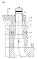
- Fig. 1 shows a system for filling cans with a viscous, pasty or lumpy filling material, which consists of one with a lower part 12, an upper part 18 and a plurality of filling cylinders 24 which are guided past the sealing plate 22.
- the filling cylinders 24 are provided with sealing flanges 26 which slide on the sealing plate 22, with each filling cylinder 24 having a quantity of the filling material during each filling process records how it will later be placed in a tin.
- the sealing plate 22 In order to enable a reliable transfer between the upper part 18 of the positioning unit and the filling cylinder 24, the sealing plate 22 must be pressed against the sealing flanges 26 of the filling cylinder 24 with a suitable pressure. This pressure must be so great that the filling material does not escape between the sealing plate 22 and the sealing flange 26. On the other hand, this pressure must not be too high, since the sliding movement between the sealing flanges 26 and the sealing plate 22 must be ensured.
- annular groove / ring spring configuration is provided between the lower part 12 and the upper part 18 of the positioning unit.
- the depth of the annular groove 20 is greater than the depth of the annular spring 14, so that a space remains between the surface of the annular spring 14 and the bottom of the annular groove 20 even when the upper part 18 is in contact with the lower part 12. In this remaining space, an annular tube 28 is inserted, which is filled with air.
- the ring hose 28 thus presses the upper part 18 with the sealing plate 22 resting thereon away from the lower part 12 in the direction of the sealing flanges 26, the contact pressure between the sealing plate 22 and the sealing flanges 26 arising from the pressure with which the ring hose 24 is applied , results.
- the annular groove 20 can optionally be arranged in the upper part 18, as shown, the annular spring 14 being a component of the lower part 12. However, the annular groove 20 can also be formed in the lower part 12, while the annular spring 14 is formed on the upper part 18.
- Fig. 3 illustrates that when the pressure in the ring hose 28 is reduced, the upper part 18 can be lowered onto the lower part 12, for example for maintenance or cleaning work.
- Fig. 4 finally shows that even if the ring hose 28 should lose air, the function of the hose is still poorly fulfilled when the through holes 10 are filled with the filling material: the filling material will push the ring hose 28 outwards and thus seal the space .
- the product pressure replaces the function of the prestressed ring hose. Even in the event of a sudden drop in pressure in the ring hose 28, the function is at least temporarily ensured.
- the proposed design of a portioning unit thus enables filling material in a filling system, in which filling cylinders are guided past a sealing plate, to be pressed onto this sealing plate with a predetermined pressure, the function being ensured in any case even if the pressure medium fails.
Landscapes
- Engineering & Computer Science (AREA)
- General Engineering & Computer Science (AREA)
- Mechanical Engineering (AREA)
- Filling Of Jars Or Cans And Processes For Cleaning And Sealing Jars (AREA)
- Basic Packing Technique (AREA)
Applications Claiming Priority (2)
| Application Number | Priority Date | Filing Date | Title |
|---|---|---|---|
| DE3813573 | 1988-04-22 | ||
| DE3813573A DE3813573C1 (enExample) | 1988-04-22 | 1988-04-22 |
Publications (1)
| Publication Number | Publication Date |
|---|---|
| EP0338197A1 true EP0338197A1 (de) | 1989-10-25 |
Family
ID=6352636
Family Applications (1)
| Application Number | Title | Priority Date | Filing Date |
|---|---|---|---|
| EP89101846A Withdrawn EP0338197A1 (de) | 1988-04-22 | 1989-02-03 | Portioniereinheit für eine Füllanlage zum Füllen von Konservendosen |
Country Status (6)
| Country | Link |
|---|---|
| US (1) | US5012958A (enExample) |
| EP (1) | EP0338197A1 (enExample) |
| JP (1) | JPH0723121B2 (enExample) |
| AU (1) | AU615057B2 (enExample) |
| DE (1) | DE3813573C1 (enExample) |
| WO (1) | WO1989010304A1 (enExample) |
Citations (4)
| Publication number | Priority date | Publication date | Assignee | Title |
|---|---|---|---|---|
| GB733797A (en) * | 1952-09-27 | 1955-07-20 | Dunlop Rubber Co | Improvements in or relating to pipe couplings |
| GB1240807A (en) * | 1969-05-29 | 1971-07-28 | Campbell Soup Co | Filling apparatus |
| EP0018464A1 (fr) * | 1977-09-20 | 1980-11-12 | Compagnie D'etudes Et De Realisation De Cybernetique Industrielle | Dispositif de commande du gonflage d'un joint d'étanchéité placé entre deux tubes coulissant l'un dans l'autre |
| EP0179975A2 (de) * | 1984-10-02 | 1986-05-07 | SIMONAZZI A. & L. S.p.A. | Kontinuierlich arbeitende Rotationsabfüllvorrichtung |
Family Cites Families (10)
| Publication number | Priority date | Publication date | Assignee | Title |
|---|---|---|---|---|
| US356122A (en) * | 1887-01-18 | Can-filling machine | ||
| US1164831A (en) * | 1913-09-24 | 1915-12-21 | George L Mcdermott | Pump. |
| US2709538A (en) * | 1951-04-07 | 1955-05-31 | Armour & Co | Filling machine |
| US3684409A (en) * | 1970-08-19 | 1972-08-15 | Manuel Claude Sanz | Distributor pump |
| CH585393A5 (enExample) * | 1974-11-22 | 1977-02-28 | Alpura Koreco Ag | |
| US4343598A (en) * | 1980-03-14 | 1982-08-10 | Friedrich Wilh. Schwing Gmbh | Viscous material pump, particularly for concrete |
| DE3113787C2 (de) * | 1981-04-04 | 1985-08-22 | Friedrich Wilh. Schwing Gmbh, 4690 Herne | Rohrweiche für Beton- oder Dickstoffkolbenpumpen |
| ATE22158T1 (de) * | 1982-01-22 | 1986-09-15 | Thomsen A F D Sales Service | Dickstoffpumpe. |
| US4624465A (en) * | 1984-08-30 | 1986-11-25 | Cefilac | Pneumatic safety seal joint made of elastomer with internal septum |
| DD234397B1 (de) * | 1985-02-01 | 1988-08-10 | Buero F Ratio Nalisierung Der | Abfuelleinrichtung fuer pulver und granulate |
-
1988
- 1988-04-22 DE DE3813573A patent/DE3813573C1/de not_active Expired
-
1989
- 1989-02-03 EP EP89101846A patent/EP0338197A1/de not_active Withdrawn
- 1989-04-19 JP JP1504071A patent/JPH0723121B2/ja not_active Expired - Lifetime
- 1989-04-19 US US07/458,645 patent/US5012958A/en not_active Expired - Fee Related
- 1989-04-19 AU AU34178/89A patent/AU615057B2/en not_active Ceased
- 1989-04-19 WO PCT/DE1989/000237 patent/WO1989010304A1/de not_active Ceased
Patent Citations (4)
| Publication number | Priority date | Publication date | Assignee | Title |
|---|---|---|---|---|
| GB733797A (en) * | 1952-09-27 | 1955-07-20 | Dunlop Rubber Co | Improvements in or relating to pipe couplings |
| GB1240807A (en) * | 1969-05-29 | 1971-07-28 | Campbell Soup Co | Filling apparatus |
| EP0018464A1 (fr) * | 1977-09-20 | 1980-11-12 | Compagnie D'etudes Et De Realisation De Cybernetique Industrielle | Dispositif de commande du gonflage d'un joint d'étanchéité placé entre deux tubes coulissant l'un dans l'autre |
| EP0179975A2 (de) * | 1984-10-02 | 1986-05-07 | SIMONAZZI A. & L. S.p.A. | Kontinuierlich arbeitende Rotationsabfüllvorrichtung |
Also Published As
| Publication number | Publication date |
|---|---|
| WO1989010304A1 (fr) | 1989-11-02 |
| DE3813573C1 (enExample) | 1989-12-07 |
| JPH03500872A (ja) | 1991-02-28 |
| AU615057B2 (en) | 1991-09-19 |
| JPH0723121B2 (ja) | 1995-03-15 |
| AU3417889A (en) | 1989-11-24 |
| US5012958A (en) | 1991-05-07 |
Similar Documents
| Publication | Publication Date | Title |
|---|---|---|
| DE2551124A1 (de) | Fuellvorrichtung fuer den gasraum eines druckbehaelters | |
| DE3832634A1 (de) | Vorrichtung zum befuehlen von saecken | |
| EP0292728A2 (de) | Stützplatte für Flaschendrehteller in Etikettiermaschinen | |
| DE3245926A1 (de) | Ausbruchspreventer | |
| EP0204937B1 (de) | Vorrichtung zum Füllen von Behältern | |
| EP0338197A1 (de) | Portioniereinheit für eine Füllanlage zum Füllen von Konservendosen | |
| EP0155622A2 (de) | Höhenverstellbares Lager zum Übertragen und Anheben bzw. Absenken schwerer Lasten von Bauwerken, insbesondere Brückenbauwerken | |
| EP0128493A1 (de) | Dichtung für Spurkettengelenke von Kettenfahrzeugen | |
| EP0047503B1 (de) | Lagerung für einen Farbkasten einer Rotationsdruckmaschine | |
| DE2447583A1 (de) | Dichtring | |
| DE1172691B (de) | Schablonendruckvorrichtung | |
| DE2252289C3 (de) | Gleitlager mit Dauerschmierung für Brücken o.dgl. Bauwerke | |
| DE2205487C3 (de) | Befestigungsvorrichtung für einen Rohrheizkörper in einer schlitzförmigen Wandöffnung eines Flüssigkeitsbehälters | |
| DE2506091B1 (de) | Abdichtungsvorrichtung | |
| DE3246058C2 (enExample) | ||
| DE2324464A1 (de) | Vorrichtung zum ausbringen von druckfarbe aus einem druckfarbenbehaelter | |
| EP0844716B1 (de) | Kabelmuffe | |
| DE2752073A1 (de) | Vorrichtung zur gleichzeitigen abgabe dosierter fluessigkeitsmengen zur medizinischen verwendung | |
| DE2217219C3 (de) | Pipettiervorrichtung | |
| DE3800941A1 (de) | Dichtungsanordnung | |
| DE10003908A1 (de) | Transport- und/oder Lagerbehälter insbesondere für radioaktives Material | |
| DE3012524A1 (de) | Dichtring-ausbauwerkzeug fuer kegelrad (hinterachse) und getriebeverlaengerung an kraftfahrzeugen | |
| DE3131517A1 (de) | Behaelter fuer aggressive fluessigkeiten | |
| DE3636193C2 (enExample) | ||
| DD225373A1 (de) | Vorrichtung zum montieren elastischer dichtelemente |
Legal Events
| Date | Code | Title | Description |
|---|---|---|---|
| PUAI | Public reference made under article 153(3) epc to a published international application that has entered the european phase |
Free format text: ORIGINAL CODE: 0009012 |
|
| AK | Designated contracting states |
Kind code of ref document: A1 Designated state(s): AT BE CH DE ES FR GB GR IT LI LU NL SE |
|
| 17P | Request for examination filed |
Effective date: 19891106 |
|
| 17Q | First examination report despatched |
Effective date: 19910715 |
|
| STAA | Information on the status of an ep patent application or granted ep patent |
Free format text: STATUS: THE APPLICATION HAS BEEN WITHDRAWN |
|
| 18W | Application withdrawn |
Withdrawal date: 19911010 |