EP0338059B1 - Flüssigkristallmischung - Google Patents
Flüssigkristallmischung Download PDFInfo
- Publication number
- EP0338059B1 EP0338059B1 EP88909475A EP88909475A EP0338059B1 EP 0338059 B1 EP0338059 B1 EP 0338059B1 EP 88909475 A EP88909475 A EP 88909475A EP 88909475 A EP88909475 A EP 88909475A EP 0338059 B1 EP0338059 B1 EP 0338059B1
- Authority
- EP
- European Patent Office
- Prior art keywords
- liquid crystal
- trans
- straight chain
- crystal material
- compounds represented
- Prior art date
- Legal status (The legal status is an assumption and is not a legal conclusion. Google has not performed a legal analysis and makes no representation as to the accuracy of the status listed.)
- Revoked
Links
- 239000004973 liquid crystal related substance Substances 0.000 title claims abstract description 374
- 239000000203 mixture Substances 0.000 title claims abstract description 145
- 239000004988 Nematic liquid crystal Substances 0.000 claims abstract description 4
- 150000001875 compounds Chemical class 0.000 claims description 131
- 239000000463 material Substances 0.000 claims description 93
- 125000004432 carbon atom Chemical group C* 0.000 claims description 45
- 125000000217 alkyl group Chemical group 0.000 claims description 40
- 125000004430 oxygen atom Chemical group O* 0.000 claims description 13
- 230000005540 biological transmission Effects 0.000 claims description 11
- 125000003545 alkoxy group Chemical group 0.000 claims description 10
- 238000009472 formulation Methods 0.000 claims description 7
- 125000001140 1,4-phenylene group Chemical group [H]C1=C([H])C([*:2])=C([H])C([H])=C1[*:1] 0.000 claims description 6
- 125000004423 acyloxy group Chemical group 0.000 claims description 6
- 125000005407 trans-1,4-cyclohexylene group Chemical group [H]C1([H])C([H])([H])[C@]([H])([*:2])C([H])([H])C([H])([H])[C@@]1([H])[*:1] 0.000 claims description 6
- PXGOKWXKJXAPGV-UHFFFAOYSA-N Fluorine Chemical group FF PXGOKWXKJXAPGV-UHFFFAOYSA-N 0.000 claims description 3
- 229910052731 fluorine Chemical group 0.000 claims description 3
- 239000011737 fluorine Chemical group 0.000 claims description 3
- 229910052739 hydrogen Inorganic materials 0.000 claims description 3
- 239000001257 hydrogen Substances 0.000 claims description 3
- 125000004435 hydrogen atom Chemical group [H]* 0.000 claims description 3
- 238000000034 method Methods 0.000 claims description 2
- 230000007935 neutral effect Effects 0.000 claims 2
- 230000006872 improvement Effects 0.000 abstract description 3
- 239000007788 liquid Substances 0.000 description 35
- BGEYOSFUJVDPRV-UHFFFAOYSA-N 2-(4-ethylphenyl)-5-propylpyrimidine Chemical compound N1=CC(CCC)=CN=C1C1=CC=C(CC)C=C1 BGEYOSFUJVDPRV-UHFFFAOYSA-N 0.000 description 33
- XWIJHTNJZNSLHB-UHFFFAOYSA-N 5-propyl-2-(4-propylphenyl)pyrimidine Chemical compound C1=CC(CCC)=CC=C1C1=NC=C(CCC)C=N1 XWIJHTNJZNSLHB-UHFFFAOYSA-N 0.000 description 33
- RZTKFRNATFGMIZ-MLRKGSHFSA-N C(CC)[C@@H]1CC[C@H](CC1)[C@@H]1CC[C@H](CC1)CCC1=CC=C(C=C1)C Chemical compound C(CC)[C@@H]1CC[C@H](CC1)[C@@H]1CC[C@H](CC1)CCC1=CC=C(C=C1)C RZTKFRNATFGMIZ-MLRKGSHFSA-N 0.000 description 33
- VRDNRAMDWPJGBD-MVBYDDMTSA-N C(CC)[C@@H]1CC[C@H](CC1)[C@@H]1CC[C@H](CC1)CCC1=CC=C(C=C1)CCC Chemical compound C(CC)[C@@H]1CC[C@H](CC1)[C@@H]1CC[C@H](CC1)CCC1=CC=C(C=C1)CCC VRDNRAMDWPJGBD-MVBYDDMTSA-N 0.000 description 33
- PZUUMRKZMNIXKL-CYWFSMGFSA-N C(CC)[C@@H]1CC[C@H](CC1)[C@@H]1CC[C@H](CC1)CCC1=CC=C(C=C1)CCCCC Chemical compound C(CC)[C@@H]1CC[C@H](CC1)[C@@H]1CC[C@H](CC1)CCC1=CC=C(C=C1)CCCCC PZUUMRKZMNIXKL-CYWFSMGFSA-N 0.000 description 33
- YZCCJRXJJVFAMB-QWZLJSJVSA-N C(CC)[C@@H]1CC[C@H](CC1)[C@@H]1CC[C@H](CC1)CCC1=CC=C(C=C1)CC Chemical compound C(CC)[C@@H]1CC[C@H](CC1)[C@@H]1CC[C@H](CC1)CCC1=CC=C(C=C1)CC YZCCJRXJJVFAMB-QWZLJSJVSA-N 0.000 description 28
- 230000000007 visual effect Effects 0.000 description 22
- RZMMNCZAJRVASP-UHFFFAOYSA-N 2-(4-ethylphenyl)-5-heptylpyrimidine Chemical compound N1=CC(CCCCCCC)=CN=C1C1=CC=C(CC)C=C1 RZMMNCZAJRVASP-UHFFFAOYSA-N 0.000 description 21
- ZHDZFSWIWPZWCF-KDNFAQGPSA-N C(CC)[C@@H]1CC[C@H](CC1)[C@@H]1CC[C@H](CC1)CCC1=CC=C(C=C1)C#N Chemical compound C(CC)[C@@H]1CC[C@H](CC1)[C@@H]1CC[C@H](CC1)CCC1=CC=C(C=C1)C#N ZHDZFSWIWPZWCF-KDNFAQGPSA-N 0.000 description 20
- OXBRRUNAAVNTOZ-SHTZXODSSA-N C1C[C@@H](CCC)CC[C@@H]1C1=CC=C(OCC)C=C1 Chemical compound C1C[C@@H](CCC)CC[C@@H]1C1=CC=C(OCC)C=C1 OXBRRUNAAVNTOZ-SHTZXODSSA-N 0.000 description 20
- 230000004044 response Effects 0.000 description 20
- OYOBZVHPZUVLSF-JCNLHEQBSA-N C1C[C@@H](CCC)CC[C@@H]1C1=CC=C(CC)C=C1 Chemical compound C1C[C@@H](CCC)CC[C@@H]1C1=CC=C(CC)C=C1 OYOBZVHPZUVLSF-JCNLHEQBSA-N 0.000 description 19
- 0 *CC(CC1)CCC1C1CCC(*)CC1 Chemical compound *CC(CC1)CCC1C1CCC(*)CC1 0.000 description 15
- RXBBPIPXHBOXOU-KESTWPANSA-N C1C[C@@H](CCCCC)CC[C@@H]1C1=CC=C(CCC)C=C1 Chemical compound C1C[C@@H](CCCCC)CC[C@@H]1C1=CC=C(CCC)C=C1 RXBBPIPXHBOXOU-KESTWPANSA-N 0.000 description 13
- 239000003989 dielectric material Substances 0.000 description 11
- CZPWVGJYEJSRLH-UHFFFAOYSA-N Pyrimidine Chemical compound C1=CN=CN=C1 CZPWVGJYEJSRLH-UHFFFAOYSA-N 0.000 description 7
- AKLNSENRWPKHFA-UHFFFAOYSA-N 5-butyl-5-pentyl-2-(2-phenylethynyl)cyclohexa-1,3-diene Chemical compound C(CCC)C1(CC=C(C=C1)C#CC1=CC=CC=C1)CCCCC AKLNSENRWPKHFA-UHFFFAOYSA-N 0.000 description 6
- BJFIEDPBYKTZKH-UHFFFAOYSA-N 5-pentyl-2-(2-phenylethynyl)-5-propylcyclohexa-1,3-diene Chemical compound C(CCCC)C1(CC=C(C=C1)C#CC1=CC=CC=C1)CCC BJFIEDPBYKTZKH-UHFFFAOYSA-N 0.000 description 6
- QNPYJPPTDXFRTR-UHFFFAOYSA-N 5-pentyl-2-(4-propylphenyl)pyrimidine Chemical compound N1=CC(CCCCC)=CN=C1C1=CC=C(CCC)C=C1 QNPYJPPTDXFRTR-UHFFFAOYSA-N 0.000 description 6
- 239000011159 matrix material Substances 0.000 description 6
- 238000002834 transmittance Methods 0.000 description 6
- 230000005684 electric field Effects 0.000 description 5
- MDUQZBFHDPNORI-HDJSIYSDSA-N CCC[C@H]1CC[C@@H](CC1)c1ccc(OC)cc1 Chemical compound CCC[C@H]1CC[C@@H](CC1)c1ccc(OC)cc1 MDUQZBFHDPNORI-HDJSIYSDSA-N 0.000 description 4
- 239000004990 Smectic liquid crystal Substances 0.000 description 4
- 230000008859 change Effects 0.000 description 4
- 230000007423 decrease Effects 0.000 description 4
- 230000000704 physical effect Effects 0.000 description 4
- CBWCLOQHNNGEAJ-UHFFFAOYSA-N 1-butyl-4-[2-(4-propylphenyl)ethynyl]benzene Chemical compound C1=CC(CCCC)=CC=C1C#CC1=CC=C(CCC)C=C1 CBWCLOQHNNGEAJ-UHFFFAOYSA-N 0.000 description 3
- SSXIKUCDZOQOKB-UHFFFAOYSA-N 4-(5-pentyl-1,3-dioxan-2-yl)benzonitrile Chemical compound O1CC(CCCCC)COC1C1=CC=C(C#N)C=C1 SSXIKUCDZOQOKB-UHFFFAOYSA-N 0.000 description 3
- XDTMQSROBMDMFD-UHFFFAOYSA-N C1CCCCC1 Chemical compound C1CCCCC1 XDTMQSROBMDMFD-UHFFFAOYSA-N 0.000 description 3
- UHOVQNZJYSORNB-UHFFFAOYSA-N c1ccccc1 Chemical compound c1ccccc1 UHOVQNZJYSORNB-UHFFFAOYSA-N 0.000 description 3
- 238000010276 construction Methods 0.000 description 3
- 230000000694 effects Effects 0.000 description 3
- 230000003287 optical effect Effects 0.000 description 3
- RYHBNJHYFVUHQT-UHFFFAOYSA-N 1,4-Dioxane Chemical compound C1COCCO1 RYHBNJHYFVUHQT-UHFFFAOYSA-N 0.000 description 2
- XCYAZBDFNGFCHG-UHFFFAOYSA-N 1-butyl-4-[2-(4-pentylphenyl)ethynyl]benzene Chemical compound C1=CC(CCCCC)=CC=C1C#CC1=CC=C(CCCC)C=C1 XCYAZBDFNGFCHG-UHFFFAOYSA-N 0.000 description 2
- PQNVCWDQMMEKNA-UHFFFAOYSA-N 1-pentyl-4-[2-(4-propylphenyl)ethynyl]benzene Chemical compound C1=CC(CCCCC)=CC=C1C#CC1=CC=C(CCC)C=C1 PQNVCWDQMMEKNA-UHFFFAOYSA-N 0.000 description 2
- WCJUJMPIFZMWOZ-UHFFFAOYSA-N 1-pentyl-4-phenylcyclohexa-2,4-diene-1-carbonitrile Chemical group C1=CC(CCCCC)(C#N)CC=C1C1=CC=CC=C1 WCJUJMPIFZMWOZ-UHFFFAOYSA-N 0.000 description 2
- MWYVODQZLABCHZ-UHFFFAOYSA-N 5-butyl-2-(2-phenylethynyl)-5-propylcyclohexa-1,3-diene Chemical compound C(CCC)C1(CC=C(C=C1)C#CC1=CC=CC=C1)CCC MWYVODQZLABCHZ-UHFFFAOYSA-N 0.000 description 2
- VDIHYZOQBIZBHO-UHFFFAOYSA-N 5-heptyl-2-(4-methoxyphenyl)pyrimidine Chemical compound N1=CC(CCCCCCC)=CN=C1C1=CC=C(OC)C=C1 VDIHYZOQBIZBHO-UHFFFAOYSA-N 0.000 description 2
- FNIPGBFUEZMVHZ-JOLHVKOESA-N C(CC)[C@@H]1CC[C@H](CC1)[C@@H]1CC[C@H](CC1)CCC1=CC=C(C=C1)F Chemical compound C(CC)[C@@H]1CC[C@H](CC1)[C@@H]1CC[C@H](CC1)CCC1=CC=C(C=C1)F FNIPGBFUEZMVHZ-JOLHVKOESA-N 0.000 description 2
- 235000010290 biphenyl Nutrition 0.000 description 2
- 238000013461 design Methods 0.000 description 2
- ZUOUZKKEUPVFJK-UHFFFAOYSA-N diphenyl Chemical compound C1=CC=CC=C1C1=CC=CC=C1 ZUOUZKKEUPVFJK-UHFFFAOYSA-N 0.000 description 2
- 238000005259 measurement Methods 0.000 description 2
- 150000003230 pyrimidines Chemical class 0.000 description 2
- 238000011160 research Methods 0.000 description 2
- 230000007704 transition Effects 0.000 description 2
- DSKOGELQRYROAA-UHFFFAOYSA-N (2-cyclohexyl-1-ethylcyclohexyl)benzene Chemical class CCC1(CCCCC1C1CCCCC1)C1=CC=CC=C1 DSKOGELQRYROAA-UHFFFAOYSA-N 0.000 description 1
- DURDZFYGFXPFAV-UHFFFAOYSA-N 1-ethoxy-4-[2-(4-methylphenyl)ethynyl]benzene Chemical compound C1=CC(OCC)=CC=C1C#CC1=CC=C(C)C=C1 DURDZFYGFXPFAV-UHFFFAOYSA-N 0.000 description 1
- LRLGRBOFFNCSQY-UHFFFAOYSA-N 2-(2-heptoxyphenyl)-5-heptylpyrimidine Chemical compound CCCCCCCOC1=CC=CC=C1C1=NC=C(CCCCCCC)C=N1 LRLGRBOFFNCSQY-UHFFFAOYSA-N 0.000 description 1
- RZGBKQIWOVKFTI-UHFFFAOYSA-N 5-ethoxy-5-methyl-2-(2-phenylethynyl)cyclohexa-1,3-diene Chemical compound C1=CC(OCC)(C)CC=C1C#CC1=CC=CC=C1 RZGBKQIWOVKFTI-UHFFFAOYSA-N 0.000 description 1
- KORMYSCDCHFFMN-GARHLSDISA-N C(CC)[C@@H]1CC[C@H](CC1)[C@@H]1CC[C@H](CC1)CC Chemical compound C(CC)[C@@H]1CC[C@H](CC1)[C@@H]1CC[C@H](CC1)CC KORMYSCDCHFFMN-GARHLSDISA-N 0.000 description 1
- IZAVEVLFPVTHBA-LTBDPCAISA-N C(CCCC)[C@@H]1CC[C@H](CC1)[C@@H]1CC[C@H](CC1)CCC1=CC=C(C=C1)C#N Chemical compound C(CCCC)[C@@H]1CC[C@H](CC1)[C@@H]1CC[C@H](CC1)CCC1=CC=C(C=C1)C#N IZAVEVLFPVTHBA-LTBDPCAISA-N 0.000 description 1
- XKRNUBKDEPFDCX-DVAIQPOTSA-N C(CCCC)[C@@H]1CC[C@H](CC1)[C@@H]1CC[C@H](CC1)CCC1=CC=C(C=C1)F Chemical compound C(CCCC)[C@@H]1CC[C@H](CC1)[C@@H]1CC[C@H](CC1)CCC1=CC=C(C=C1)F XKRNUBKDEPFDCX-DVAIQPOTSA-N 0.000 description 1
- GJHKWLSRHNWTAN-QAQDUYKDSA-N C1C[C@@H](CCCCC)CC[C@@H]1C1=CC=C(OCC)C=C1 Chemical compound C1C[C@@H](CCCCC)CC[C@@H]1C1=CC=C(OCC)C=C1 GJHKWLSRHNWTAN-QAQDUYKDSA-N 0.000 description 1
- BLNICDDWTDNARD-UHFFFAOYSA-N CC(CN)CNO Chemical compound CC(CN)CNO BLNICDDWTDNARD-UHFFFAOYSA-N 0.000 description 1
- GXLOSSKAKQGKJC-BIAGXBKMSA-N CCC[C@H]1CC[C@@H](CC1)[C@H]1CC[C@H](C)CC1 Chemical compound CCC[C@H]1CC[C@@H](CC1)[C@H]1CC[C@H](C)CC1 GXLOSSKAKQGKJC-BIAGXBKMSA-N 0.000 description 1
- DAUXIZYWZXMLAF-WKILWMFISA-N CCC[C@H]1CC[C@H](CCc2ccc(cc2)C#N)CC1 Chemical compound CCC[C@H]1CC[C@H](CCc2ccc(cc2)C#N)CC1 DAUXIZYWZXMLAF-WKILWMFISA-N 0.000 description 1
- PSRNBISYSWJJQP-UHFFFAOYSA-N C[O](c(cc1)ccc1O)=C Chemical compound C[O](c(cc1)ccc1O)=C PSRNBISYSWJJQP-UHFFFAOYSA-N 0.000 description 1
- UILATXGYUKHPEB-UHFFFAOYSA-N C[O]1CC=CCC1 Chemical compound C[O]1CC=CCC1 UILATXGYUKHPEB-UHFFFAOYSA-N 0.000 description 1
- JFDZBHWFFUWGJE-UHFFFAOYSA-N N#Cc1ccccc1 Chemical compound N#Cc1ccccc1 JFDZBHWFFUWGJE-UHFFFAOYSA-N 0.000 description 1
- 238000000149 argon plasma sintering Methods 0.000 description 1
- 239000004305 biphenyl Substances 0.000 description 1
- 239000002178 crystalline material Substances 0.000 description 1
- CTBBGDYEILDJLA-UHFFFAOYSA-N cyclohexyl 1-cyclohexylcyclohexane-1-carboxylate Chemical class C1CCCCC1(C1CCCCC1)C(=O)OC1CCCCC1 CTBBGDYEILDJLA-UHFFFAOYSA-N 0.000 description 1
- IGARGHRYKHJQSM-UHFFFAOYSA-N cyclohexylbenzene Chemical compound C1CCCCC1C1=CC=CC=C1 IGARGHRYKHJQSM-UHFFFAOYSA-N 0.000 description 1
- WVIIMZNLDWSIRH-UHFFFAOYSA-N cyclohexylcyclohexane Chemical class C1CCCCC1C1CCCCC1 WVIIMZNLDWSIRH-UHFFFAOYSA-N 0.000 description 1
- 239000000975 dye Substances 0.000 description 1
- 125000001495 ethyl group Chemical group [H]C([H])([H])C([H])([H])* 0.000 description 1
- 230000001747 exhibiting effect Effects 0.000 description 1
- 238000002474 experimental method Methods 0.000 description 1
- 238000004519 manufacturing process Methods 0.000 description 1
- 125000000956 methoxy group Chemical group [H]C([H])([H])O* 0.000 description 1
- 238000012986 modification Methods 0.000 description 1
- 230000004048 modification Effects 0.000 description 1
- 125000003136 n-heptyl group Chemical group [H]C([H])([H])C([H])([H])C([H])([H])C([H])([H])C([H])([H])C([H])([H])C([H])([H])* 0.000 description 1
- 125000001280 n-hexyl group Chemical group C(CCCCC)* 0.000 description 1
- 125000006609 n-nonyloxy group Chemical group 0.000 description 1
- -1 n-pentyloxy, n-heptyloxy Chemical group 0.000 description 1
- 125000004123 n-propyl group Chemical group [H]C([H])([H])C([H])([H])C([H])([H])* 0.000 description 1
- HOEPDNHULZDPEP-UHFFFAOYSA-N phenyl 1-cyclohexylcyclohexane-1-carboxylate Chemical class C1CCCCC1(C1CCCCC1)C(=O)OC1=CC=CC=C1 HOEPDNHULZDPEP-UHFFFAOYSA-N 0.000 description 1
- OPYYWWIJPHKUDZ-UHFFFAOYSA-N phenyl cyclohexanecarboxylate Chemical class C1CCCCC1C(=O)OC1=CC=CC=C1 OPYYWWIJPHKUDZ-UHFFFAOYSA-N 0.000 description 1
- 230000035945 sensitivity Effects 0.000 description 1
- 239000000126 substance Substances 0.000 description 1
- 238000004381 surface treatment Methods 0.000 description 1
Classifications
-
- C—CHEMISTRY; METALLURGY
- C09—DYES; PAINTS; POLISHES; NATURAL RESINS; ADHESIVES; COMPOSITIONS NOT OTHERWISE PROVIDED FOR; APPLICATIONS OF MATERIALS NOT OTHERWISE PROVIDED FOR
- C09K—MATERIALS FOR MISCELLANEOUS APPLICATIONS, NOT PROVIDED FOR ELSEWHERE
- C09K19/00—Liquid crystal materials
- C09K19/02—Liquid crystal materials characterised by optical, electrical or physical properties of the components, in general
- C09K19/0208—Twisted Nematic (T.N.); Super Twisted Nematic (S.T.N.); Optical Mode Interference (O.M.I.)
-
- C—CHEMISTRY; METALLURGY
- C09—DYES; PAINTS; POLISHES; NATURAL RESINS; ADHESIVES; COMPOSITIONS NOT OTHERWISE PROVIDED FOR; APPLICATIONS OF MATERIALS NOT OTHERWISE PROVIDED FOR
- C09K—MATERIALS FOR MISCELLANEOUS APPLICATIONS, NOT PROVIDED FOR ELSEWHERE
- C09K19/00—Liquid crystal materials
- C09K19/04—Liquid crystal materials characterised by the chemical structure of the liquid crystal components, e.g. by a specific unit
- C09K19/42—Mixtures of liquid crystal compounds covered by two or more of the preceding groups C09K19/06 - C09K19/40
Definitions
- the invention relates to the improvement of a twisted nematic liquid crystal display device operating in the high multiplex mode with a very high contrast and with a particularly steep electro-optical characteristic.
- the device is operating in the first Gooch and Tarry transmission minimum.
- the invention furthermore relates to new liquid crystal mixtures which are most suited for use of matrix type liquid crystal display devices driven by time sharing and which have a ratio of the elastic constants K 3 /Ki as small as possible but not more than 0.8 and a ratio of ⁇ / ⁇ ⁇ of at most 0.5.
- Such dielectrics are used in the matrix type liquid crystal display devices driven by time sharing according to the invention.
- nematic or nematic-cholesteric liquid-crystalline materials are utilized for liquid-crystal display elements in order to effect significant changes in their optical properties, such as light transmission, light scattering, birefringence, reflectance or color, under the influence of electric fields.
- the functioning of display elements of this type is based here, for example, on the phenomena of dynamic scattering, the deformation of aligned phases or the Schadt-Helfrich effect in the twisted cell.
- liquid-crystal display elements especially those based on the twisted nematic cell (TN cell) have gained particular importance recently, because they can be operated with relatively low control voltages which can be readily made available even by small batteries Moreover, these display elements have hitherto been the best which can be constructed as matrix display elements which allow the presentation of a high information density without an intolerably large number of control lines, lead-ins and lead-outs.
- TN cell twisted nematic cell
- the TN cell in particular in the form of matrix display elements, still raises considerable difficulties. These include above all the more or less pronounced dependence of the contrast on the angle of observation and the restricted multiplexing capacity.
- Operation margin and contrast of liquid crystal elements are determined by voltage-luminance property. Namely, as the change in transmittance to the change in intensity of electric field applied to liquid crystal is sharp, allowance for the operation margin can be large and contrast can be enhanced. Sharpness in voltage-luminance property is expressed by ratio y of voltage V so in which transmittance becomes 50 % to threshold voltage V c . As the ⁇ value approximates to 1, the aforesaid change in transmittance is sharp so that operation margin can broadened and contrast can be increased.
- time sharing-driven liquid crystal elements have an increased time sharing number and one selection period becomes short so that it is required that a response speed be fast.
- This response speed depends most greatly on the intensity of an electric field applied to liquid crystal. Namely, a thin layer thickness d of liquid crystal provides an intense intensity of electric field so that liquid crystal molecules behave at a high speed.
- matrix type liquid crystal display devices which are driven by high time sharing require that:
- liquid crystal compounds having a small K 33 /K 11 value In operating the conventional liquid crystal compositions described above in time sharing-driven devices, the ⁇ property is not so improved since values of K 33 /K 11 and ⁇ / ⁇ ⁇ are not small. Further due to large An.d, visual angle property is also poor. In case that values of K 33 /K 11 and ⁇ / ⁇ ⁇ are increased, liquid crystal compounds having a small K 33 /K 11 value generally have a high viscosity and a tendency to form smectic phases so that their response speed decreases. Further liquid crystal compositions having a small ⁇ / ⁇ ⁇ value involve problems that their response speed becomes slow due to a small ⁇ and a high voltage is required for operation.
- EP-A-174 541 teaches TN LCD's with a steep electrooptical characteristic curve. Liquid crystal mixtures with pyrimidine compounds are disclosed in EP-A-151 446.
- an object of the present invention is to provide liquid crystal compositions for time sharing drive having small K 33 /K 11 and small A ⁇ / ⁇ ⁇ , in order to improve response speed, ⁇ property and visual angle property in time sharing-driven liquid crystal display devices.
- the present invention has been made based on a new finding that when values of A ⁇ / ⁇ ⁇ and K 33 /K 11 of liquid crystal compositions become extremely small in time sharing-driven liquid crystal display devices, response speed and ⁇ property are markedly improved in such a range of ⁇ n.d that does not meet the equation (1) described above and in this case, the liquid crystal compositions are most suited for use in time sharing-driven liquid crystal display devices.
- a subject of the invention is the improvement of a twisted nematic liquid crystal display device operating in the high multiplex mode and having a high contrast, wherein the liquid crystal mixture has a ratio of the elastic constants K 3 /Ki as small as possible but not more than 0.8 and a ratio of D E / E1 of at most +0.5.
- the electro-optical characteristic curve in the first transmission minimum is at least as steep or even steeper as that curve in the second such transmission minimum.
- the steepness in the second transmission minimum is measured in a display device which is identical to that operated in the first minimum except that the layer thickness is enlarged, in an appropriate manner for operation in the second minimum.
- a further subject of the invention is a method of simultaneously minimizing the dependence of contrast on the angle of observation of an electro-optical display element based on a liquid crystal mixture and of maximizing its multiplexing capacity by maximizing its steepness of its characteristic curve, comprising operating the element in the first Gooch and Tarry transmission minimum, selecting a mixture having a K 3 /Ki ratio as small as possible but not more than 0.8 and a ratio of D E / E1 of at most 0.5.
- the construction of the liquid crystal display element according to the invention from polarizers, electrode base plates and electrodes with such a surface treatment that the preferential orientation of the particular adjoining liquid crystal molecules is usually twisted by 90 from one electrode to the other, corresponds to the type of construction conventional for such display elements.
- the concept of the conventional type of construction is here taken in a very wide sense and also comprises all the variations and modifications, known from the literature, of the twisted nematic cell, and in particular also matrix display elements.
- An essential difference between the display elements according to the invention and those hitherto conventional and based on the twisted nematic cell is, however, the choice of the liquid crystal parameters in the liquid crystal layer.
- the K 3 /K i ratio in the conventional liquid-crystalline phases for display elements of this type is at least > 0.8 and the ⁇ / ⁇ ⁇ ratio is normally between 1.2 and 1.7
- the K 3 /Ki ratio in the display elements according to the invention is 0.8 and ⁇ / ⁇ ⁇ is 0.5.
- the K 3 /K, ratio in the display elements according to the invention preferably is 0.4 to 0.8 and ⁇ / ⁇ ⁇ preferably is 0.04 to 0.3.
- Particularly preferred dielectrics are those, wherein K 3 /Ki is 0.2 to 0.75 and ⁇ / ⁇ ⁇ is 0.1 to 0.3.
- the thickness of a liquid crystal layer of the display element according to the invention and/or the optical anisotropy An of the liquid crystal material are chosen such that the value of 550 nm, normally used for the maximum sensitivity of the human eye, being taken for the wavelength X.
- the layer thicknesses of the display elements according to the invention can, for example, be within the range from 2 to 10 ⁇ m.
- the smallest possible layer thicknesses are chosen, the lower limit of d being determined by the quality standards required for mass production.
- a particularly preferred range of d is thus 3 to 8 ⁇ m, in particular 4 to 7 ⁇ m.
- Liquid-crystalline dielectrics the material parameters of which are within the ranges according to the invention, can be prepared from conventional liquid-crystalline base materials. Numerous such materials are known from the literature. Preferably, the dielectrics according to the invention comprise at least five components.
- the dielectrics used for the display elements according to the invention comprise
- the liquid crystal composition is composed of a liquid crystal compound of pyrimidine type, as a main component, having formulated therein a small quantity of a liquid crystal compound having a distinct positive ⁇ value.
- the liquid crystal composition of the present invention can also be obtained by formulating a liquid crystal compound having a negative or substantially 0 ⁇ value, in addition to the liquid crystal mixture described above.
- values of K 33 /K 11 and A ⁇ / ⁇ ⁇ are reduced by the use of a liquid crystal having particularly large K 11 in large quantities and a liquid crystal having large ⁇ 1 in large quantities and, the liquid crystal composition has a positive A ⁇ as a whole.
- the second liquid crystal material can be absent if the first and third liquid crystal material is selected in such a manner that the resulting mixture has a slightly positive A ⁇ and a A ⁇ in the range of 0.04 to 0.3.
- liquid crystal compounds of pyrimidine type described above are preferably represented by general formula (la) described below.
- R 1 represents R
- liquid crystal compounds of pyrimidine type described above have a small K 33 /K 11 value of approximately 0.55, and K 11 is as large as about 1.8 x 10- 2. Further ⁇ ⁇ is in a range of approximately +0.9 to +2.5.
- R 1 preferably is n-alkyl having 3 to 9 carbon atoms.
- R 2 preferably is ethyl, n-propyl or n-alkoxy having 5 to 9 carbon atoms.
- pyrimidines of formula la are preferred wherein R 2 is methoxy.
- Components of formula (la) wherein R 1 is n-alkyl of 6 to 9 carbon atoms and R 2 is n-alkoxy of 5 to 9 carbon atoms are preferably selected as components of the mixtures according to this invention. Especially preferred are components wherein R 1 is n-hexyl or n-heptyl and R 2 is n-pentyloxy, n-heptyloxy or n-nonyloxy.
- liquid crystal compounds of pyrimidine type preferably liquid crystal compounds shown in Table 1 are used. Their physical properties are also shown in the same table. Among the liquid crystal compounds exemplified in Table 1, preferably at least one of them is formulated to make the first liquid crystal material.
- liquid crystal compounds having a distinct positive ⁇ value there can be used for example liquid crystal compounds of dioxane type, phenycyclohexane type, biphenyl type or pyrimidine type, which are used to render the ⁇ value of the liquid crystal composition positive.
- the second liquid crystal material comprises at least one of liquid crystal compounds represented by the general formulae IIf to IIh: wherein
- the liquid crystal compounds have the dielectric anisotropy ⁇ value is +3 or more; it is particularly desired that the ⁇ value be in a range of + 12 to +40 and viscosity value be 20 to 60 cp.
- Liquid crystal compounds as shown in Table 2 can be used among others.
- the liquid crystal compounds exemplified in Table 2 preferably at least one compound is formulated to make the second liquid crystal material.
- liquid crystal compound having a negative or substantially 0 ⁇ ⁇ value there can be used liquid crystal compounds of phenylcyclohexane type (German Patent 26 36 684), phenyl cyclohexane carboxylates (German Patent 24 29 093), cyclohexyl cyclohexanes (USP 4,622,164), biphenylcyclohexanes (Japanese Patent 1,311,608), phenyl cyclohexylcyclohexane carboxylates (Japanese Patent 1,297,121), 1-phenyl-2-cyclohexylcyclohexylethanes (USP 4,606,845), cyclohexyl cyclohexylcyclohexane carboxylates (Japanese Patent 1,297,121), 4,4'-biscyclohexylbiphenyls (USP 4,331,552) and 4,4'-biscyclohexyl-2-fluor- bi
- liquid crystal compounds are low viscosity liquid crystal compounds for controlling viscosity, high temperature liquid crystal for raising N-I point and liquid crystals for suppressing smectic phases.
- low viscosity liquid crystal compounds there can be used liquid crystal compounds shown in Table 3 which show ⁇ of approximately 6 to 20 mPa.s.
- liquid crystal compounds shown in Table 4 having N-I point of approximately 130 to 330 ° C. ⁇ is approximately 13 to 65 mPa.s.
- R is preferably alkyl of 1 to 10 carbon atoms. A particularly preferred range is 1 to 5 carbon atoms.
- the third liquid crystal material comprises preferably liquid crystal compounds having a dielectric anisotropy of -1 to + 1.
- These liquid crystal compounds are represented by general formulas described below: wherein R 7 , R 9 , R 11 and R 13 to R 24 represents R; and R 8 , R 1 and R 12 represents R or OR, R being in each case indepently a straight chain alkyl group having 1 to 12 carbon atoms two oxygen atoms not being directly attached to each other.
- liquid crystal compounds are composed of low viscosity liquid crystal compounds for controlling visosity and high temperature liquid crystal compounds for raising N-I point. By selectively formulating these liquid crystal compounds, a tendency that smectic phases appear is suppressed.
- liquid crystal compounds of general formulas (VI), (VII) and (VIII) shown in Tables 3, 4 and 5, respectively, which show ⁇ of approximately 6 to 20 cp.
- liquid crystal compounds of general formulas (IX), (X), (XI), (XII), (XIII) and (XIV) described above and shown in Tables 6, 7, 8, 9, 10 and 11, respectively. These high temperature liquid crystal compounds have a clearing point (N-I point) of approximately 130 ° C to 330 ° C.
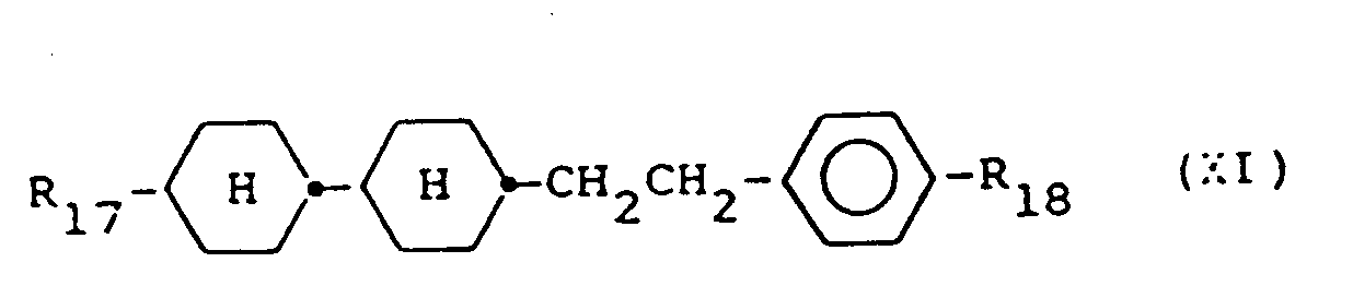
- the liquid crystal compound represented by general formula (XI) has a viscosity of 13 to 19 mPa.s and is used to increase splay elasticity constant K 11 .
- liquid crystal compounds represented by general formulae (VI) to (XIV) are those in which R be an alkyl group having 1 to 10 carbon atoms. In particular, it is desired that R be an alkyl group having 1 to 5 carbon atoms.
- At least one of the liquid crystal compounds shown in these Tables 6 to 11 is formulated to make the third liquid crystal material.
- At least one of the liquid crystal compounds shown in these Tables 3, 4 and 5 and at least one of the compounds shown in Tables 6 to 11 may be used for said third liquid crystal material.
- Preferred devices according to the invention are those, wherein the liquid crystal dielectric comprises at least five components.
- the first liquid crystal material and the second liquid crystal material are formulated in the composition.
- the first liquid crystal material is formulated so as not to exceed 90 wt% and the second liquid crystal material is formulated in an amount of less than 10 wt% so that the A E value does not become excessively large.
- the first, second and third liquid crystal materials are formulated, respectively, the first liquid crystal material is formulated in an amount of 10 wt% or more as the minimum formulation ratio that is necessary for exhibiting an effect of lowering the K 33 /K 11 value.
- the second liquid crystal material is formulated in an amount of less than 10 wt% in such a manner that the A E value does not increase unnecessarily; and the third liquid crystal material is formulated in an amount of less than 90 wt%.
- the liquid crystal composition using a low viscosity liquid crystal as the third liquid crystal material high speed response can be achieved and such a composition is suited for television display.
- first, second and third liquid crystal materials be formulated in amounts of 30 wt% or more, less than 10 wt% and less than 70 wt%, respectively. It is more preferred that the first, second and third liquid crystal materials be formulated in amounts of 30 to 65 wt%, less than 5 wt% and 35 to 70 wt%, respectively.
- said second liquid crystal material comprises one or more liquid crystal materials represented by general formula (II): wherein R 3 represents a straight chain alkyl group having 1 to 12 carbon atoms
- said third liquid crystal material comprises liquid crystal compounds represented by general formulae: wherein R 7 , R 17 and R 1 8 independently represent a straight chain alkyl group, having 1 to 12 carbon atoms, R 8 represents a straight chain alkyl group a straight chain alkoxy group or a straight chain alkanoyloxy group having 1 to 12 carbon atoms, and comprises 5 to 25 wt% of liquid crystal compounds represented by general formula (VI), 20 to 35 wt% of liquid crystal compounds represented by general formula (XI).
- these mixtures additionally comprise 2 to 10 wt% of liquid crystal compounds represented by general formula (IX): where R 13 and R 14 independently represent a straight chain alkyl group having 1 to 12 carbon atoms.
- said second liquid crystal material comprises one or more liquid crystal compounds represented by the formula (II) below: wherein R 3 represents a straight chain alkyl group having 1 to 12 carbon atoms, and said third liquid crystal material comprises 5 to 45 wt% of liquid crystal compounds represented by the formula (VI) and (VII) below, and optionally 5 to 25 wt%, 10 to 25 wt%, and 20 to 25 wt%, respectively, of liquid crystal compounds represented by the formulae (IX), (X), and (XI) below: wherein R 7 , R 9 and R 13 to R 18 independently represent a straight chain alkyl group having 1 to 12 carbon atoms.
- R 10 represents a straight chain alkyl group or straight chain alkoxy group having 1 to 12 carbon atoms
- R 8 represents a straight chain alkyl group, a straight chain alkoxy group or a straight chain alkanoyloxy group having 1 to 12 carbon atoms.
- these mixtures comprise as said third liquid crystal material 10 to 40 wt% of liquid crystal compounds represented by the formulae (VI) and (VII).
- said second liquid crystal material comprises one or more liquid crystal compounds represented by the formula (II) below: wherein R 3 represents a straight chain alkyl group having 1 to 12 carbon atoms, and said third liquid crystal material comprises 15 to 30 wt%, less than 10 wt%, and 20 to 40 wt%, respectively, of liquid crystal compounds represented by the formulae (VI), (IX) and (X) below, and optionally 5 to 45 wt% of liquid crystal compounds represented by the formula (VII) below: wherein R 7 , R 3 and R13 to R 16 independently represent a straight chain alkyl group having 1 to 12 carbon atoms, R 10 represents a straight chain alkyl group or straight chain alkoxy group having 1 to 12 carbon atoms, and R 8 represents a straight chain alkyl group, a straight chain alkoxy group or a straight chain alkanoyloxy group having 1 to 12 carbon atoms.
- R 3 represents a straight chain alkyl group having 1 to 12 carbon atoms
- said third liquid crystal material
- these mixtures comprise less than 42.6 wt% of liquid crystal compounds represented by the general formula (VII).
- Said compounds of formulae (XV) and (XVI) are preferably present in an amount of 5 to 15 wt%.
- liquid crystal compound respresented by general formula (II) having particularly large dielectric anisotropy ⁇ ⁇ and a small D E / E1 value as the second liquid crystal material.
- the liquid crystal material represented by general formula (II) be formulated in a proportion of 10 wt% or less, most desirably 5 wt% or less.
- At least one of low viscosity liquid crystal compounds represented by general formulas (VI), (VII) and (VIII) or, in addition to the low viscosity liquid crystal compounds, at least one of high temperature liquid crystals represented by general formulas (IX), (X), (XI), (XII), (XIII) and (XIV) are formulated.
- the low viscosity liquid crystal compounds at least one of or both of the liquid crystal compound represented by general formula (VI) and the liquid crystal compound represented by general formula (VII) is/are formulated.
- liquid crystal compound represented by general formula (VI) is formulated as the low viscosity liquid crystal compound
- liquid crystal compounds represented by general formulas (VI), (IX) and (XI) preferred proportions to be formulated are 15 to 30 wt%, 10 wt% or less and 20 to 40 wt%, respectively, most preferably 17 or 27 wt%, 2 to 10 wt% and 23 to 30 wt%, respectively.
- liquid crystal compounds represented by general formulas (VI) and (VII) are formulated as the low viscosity liquid crystal compounds
- the liquid crystal compound represented by general formula (VII) be formulated in a proportion of 5 to 42.6 wt%.
- the second liquid crystal material can also be formulated with pyrimidine type liquid crystal compounds.
- liquid crystal compounds represented by general formula (V) are used as the second liquid crystal material, in which at least one of the liquid crystal compounds, represented by general formula (IX), (X) and (XI) is formulated.
- liquid crystal composition of the present invention is formulated in such that the D E / E1 value ranges from 0.12 to 0.5 and the K 33 /Ki value is 0.8 or less.
- Preferred dielectrics are those, wherein the formulation ratios of said first liquid crystal material, said second liquid crystal material and said third liquid crystal material are at least 30 wt%, less than 10 wt% and less than 70 wt%, respectively.
- Particularly preferred dielectrics are those, wherein the formulation ratios of said first liquid crystal material, said second liquid crystal material and said third liquid crystal material are 30 to 65 wt%, less than 5 wt% and 35 to 70 wt%, respectively.
- Such dielectrics can additionally contain dyes and/or doping substances in the usual quantities, unless the liquid crystal parameters are thus taken out of the ranges according to the invention.
- liquid crystal compositions are sealed between base plates facing to each other in which electrodes are formed, so as to twist-orient the liquid crystal molecules to almost 90 and, a voltage for time sharing drive is applied to a large number of facing electrodes.
- the layer thickness of liquid crystal in liquid crystal elements is set to 7.0 ⁇ m or less.
- Example 1 indicates a composition in which the first liquid crystal material is formulated in a proportion of 30 wt%;
- Example 2 indicates a liquid crystal composition in which the first liquid crystal material is formulated in the smallest proportion; and
- Examples 3 and 4 indicate liquid crystal compositions in which the second liquid crystal material is formulated in the largest proportion.
- Example 5 only the liquid crystal compound represented by general formula (VII) is formulated as the low viscosity liquid crystal compound.
- liquid crystal compound represented by general formula (VI) is used as the low viscosity liquid crystal compound; in this case, the liquid crystal compound represented by general formula (IX), (X), (XI) or (XIII) is selectively formulated as the high temperature liquid crystal compound.
- Table 13 shows liquid crystal compositions using the liquid crystal compounds represented by general formulas (VI) and (VII) as the third liquid crystal material.
- the low viscosity liquid crystal compound represented by general formula (VIII) is additionally formulated to provide a liquid crystal composition having an extremely low viscosity.
- Examples 27 through 48 shown in Table 13 indicate liquid crystal compositions in which the liquid crystal compounds represented by general formulas (IX), (X), (XI), (XII) and (XIII) are selectively formulated.
- Examples of the liquid crystal compositions in accordance with the present invention using the liquid crystal compound represented by general formula (IV) or (V) as the second liquid crystal material are shown in Table 14.
- the liquid crystal compound represented by general formula (VI) is formulated as the third liquid crystal material and the liquid crystal compounds represented by general formulas (VII) to (IX) are selectively formulated.
- dielectric anisotropy ⁇ ⁇ is as relatively small as + 12 or less but the value of a ratio of dielectric anisotropy ⁇ ⁇ to a dielectric constant in the direction perpendicular to the molecular axis of liquid crystal, D E / E1 , is as extremely small as 0.5 or less.
- measurement values of elasticity constant ratio K 33 /K 11 are shown in Table 16, with respect to major liquid crystal compositions.
- Table 16 in the liquid crystal compositions of the present invention, liquid crystal compounds having a small elasticity constant ratio K 33 /K 11 value and liquid crystal compounds having a particularly large splay elasticity constant K 11 are formulated so that the elasticity constant ratio K 33 / K 11 value of the liquid crystal compositions is as extremely small as 0.8 or less.
- the liquid crystal composition of the present invention has small t ON and t OFF and response speed is fast because the K 33 /K 11 value is rendered small by increasing the K 11 value. Further by increasing ⁇ 1, teh A ⁇ / ⁇ value reduced so that there is no necessity to reduce the A ⁇ value excessively and, A ⁇ value is relatively large though the A ⁇ / ⁇ value is small. Therefore, increase of V c can be relatively reduced, as shown by the equation (4). Accordingly, rise in operation voltage is small.
- the liquid crystal display element using the liquid crystal composition of the present invention provides the best ⁇ property when the ⁇ n.d value is in a small range, this giving good visual angle properties and rapid response speed and, high contrast, whereby operation margin can be broadened.
- liquid crystal composition of the present invention is most suited for liquid crystal display elements for high time share driving.
- Table 17 indicates constitutional factors of the liquid crystal display element and electro- optical properties thereof.
- the numbering of liquid crystal element corresponds to the number of composition in the liquid crystal composition used.
- Threshold voltage V th is a voltage applied when the contrast shows the maximum.
- response speed is defined to be value of (Tr + Tp)/2, when rise time is Tr until luminance reaches from 10 % to 90 % and trailing time is Tp until reaches from 90 % to 10 %.
- the An.d value is in a range sufficiently smaller than 1.1, contrast is high and the ⁇ property is also good.
- the elasticity constant ratio K 33 /Ki value is 0.8 or less and the ⁇ / ⁇ value is 0.5 or less.
- This visual angle property is good, namely, indicates that visual angle is widened, as the value approximates to 1.
- the liquid crystal display element using the liquid crystal composition of the present invention is excellent also in visual angle properties. That is, the liquid crystal display elements using the liquid crystal compositions in the aforesaid examples show excellent properties in contrast, operational margin and visual angle properties and can respond at a sufficiently high speed, using driving signals of a voltage obtained by ordinary driving circuits using integral circuits.
- Liquid crystal display elements for displaying animations such as television images, etc. require high speed response of 30 msec or more; in this case, when the An.d value of the liquid crystal display elements is large, the visual angle properties are worsened and its response speed becomes slow and further when the An.d value is small, contrast decreases so that the An.d value is desirably in a range of 0.55 to 0.70. Further when the anisotropy in refractive index An of the liquid crystal composition is large, the visual angle properties are worsened so that the An value is desirably 0.14 or less. Furthermore, when the layer thickness d value of liquid crystal becomes large, a response speed becomes slow so that the layer thickness d value of liquid crystal is desirably 0.7 ⁇ m or less.
- the liquid crystal compositions for obtaining such liquid crystal display elements for displaying animations have their elasticity constant ratio K 33 /K i value of 0.8 or less and their ⁇ ⁇ / ⁇ ⁇ value of 0.5 or less. The smaller these values, the more are the electro-optical properties of the liquid crystal display elements improved.
- liquid crystal composition of the present invention is suited for highly time share-driven liquid crystal display elements and, in particular, most suited for use in liquid crystal display elements requiring high contrast, high speed response and wide visual angle as in television receivers.
- K 11 can be increased thereby to decrease K 33 /K 11 , by formulating pyrimidine type liquid crystal compounds therein as main components. Further liquid crystal compounds having a negative or almost null dielectric anisotropy are mainly formulated and a small amount of liquid crystal compounds having a positive dielectric anisotropy is formulated therein so that ⁇ can be increased thereby to reduce the ⁇ / ⁇ value. Accordingly, the liquid crystal compositions enable to operation of time sharing-driven liquid crystal display devices at high contrast and high speed and also enable to broadening visual angle.
- liquid crystal compositions according to this invention are given below:
- a liquid crystalline composition consisting of
- a liquid crystalline composition consisting of
- a liquid crystalline composition consisting of
- a liquid crystalline composition consisting of
- a liquid crystalline composition consisting of
- a liquid crystalline composition consisting of
- a liquid crystalline composition consisting of
- a liquid crystalline composition consisting of
- a liquid crystalline composition consisting of
- a liquid crystalline composition consisting of
- a liquid crystalline composition consisting of
- a liquid crystalline composition consisting of
- a liquid crystalline composition consisting of
- a liquid crystalline composition consisting of
- a liquid crystalline composition consisting of
- a liquid crystalline composition consisting of
- a liquid crystalline composition consisting of
- a liquid crystalline composition consisting of
- a liquid crystalline composition consisting of
- a liquid crystalline composition consisting of
- a liquid crystalline composition consisting of
- a liquid crystalline composition consisting of
- a liquid crystalline composition consisting of
- a liquid crystalline composition consisting of
- a liquid crystalline composition consisting of
- a liquid crystalline composition consisting of
- a liquid crystalline composition consisting of
- a liquid crystalline composition consisting of
- a liquid crystalline composition consisting of
- a liquid crystalline composition consisting of
- a liquid crystalline composition consisting of
- a liquid crystalline composition consisting of
- a liquid crystalline composition consisting of
- a liquid crystalline composition consisting of
Landscapes
- Chemical & Material Sciences (AREA)
- Crystallography & Structural Chemistry (AREA)
- Engineering & Computer Science (AREA)
- Materials Engineering (AREA)
- Organic Chemistry (AREA)
- Liquid Crystal Substances (AREA)
Claims (28)

wobei auf das zweite Flüssigkristallmaterial verzichtet werden kann, falls das erste und dritte Flüssigkristallmaterial so gewählt werden, daß die entstehende Mischung ein leicht positives Δ∈ und ein Δ∈/∈┴ im Bereich von 0,04 bis 0,3 besitzt.


wobei R jeweils unabhängig eine geradkettige Alkylgruppe mit bis zu 12 Kohlenstoffatomen bedeutet, worin eine oder zwei nichtbenachbarte CH2-Gruppen durch -O- oder -CH=CH-ersetzt sein können, wobei zwei Sauerstoffatome nicht direkt miteinander verbunden sind.


wobei R jeweils unabhängig eine geradkettige Alkylgruppe mit bis zu 12 Kohlenstoffatomen bedeutet, worin eine oder zwei nichtbenachbarte CH2-Gruppen durch -O- oder -CH=CH-ersetzt sein können, wobei zwei Sauerstoffatome nicht direkt miteinander verbunden sind.


wobei R jeweils unabhängig eine geradkettige Alkylgruppe mit bis zu 12 Kohlenstoffatomen bedeutet, worin eine oder zwei nichtbenachbarte CH2-Gruppen durch -O- oder -CH=CH-ersetzt sein können, wobei zwei Sauerstoffatome nicht direkt miteinander verbunden sind.


wobei auf das zweite Flüssigkristallmaterial verzichtet werden kann, falls das erste und dritte Flüssigkristallmaterial so gewählt werden, daß die entstehende Mischung ein leicht positives AE und ein Δ∈/∈┴ im Bereich von 0,04 bis 0,3 besitzt.
Applications Claiming Priority (4)
| Application Number | Priority Date | Filing Date | Title |
|---|---|---|---|
| JP62263148A JP2511478B2 (ja) | 1987-10-19 | 1987-10-19 | 時分割駆動用液晶組成物 |
| JP263148/87 | 1987-10-19 | ||
| EP88100274 | 1988-01-12 | ||
| EP88100274 | 1988-01-12 |
Publications (2)
| Publication Number | Publication Date |
|---|---|
| EP0338059A1 EP0338059A1 (de) | 1989-10-25 |
| EP0338059B1 true EP0338059B1 (de) | 1993-04-21 |
Family
ID=26113556
Family Applications (1)
| Application Number | Title | Priority Date | Filing Date |
|---|---|---|---|
| EP88909475A Revoked EP0338059B1 (de) | 1987-10-19 | 1988-10-15 | Flüssigkristallmischung |
Country Status (3)
| Country | Link |
|---|---|
| EP (1) | EP0338059B1 (de) |
| JP (1) | JPH02503093A (de) |
| WO (1) | WO1989003867A1 (de) |
Families Citing this family (12)
| Publication number | Priority date | Publication date | Assignee | Title |
|---|---|---|---|---|
| US4913532A (en) * | 1987-10-19 | 1990-04-03 | Casio Computer Co., Ltd. | Liquid crystal composition and liquid crystal display device using the same |
| US6004479A (en) * | 1988-07-13 | 1999-12-21 | Merck Kgaa | Matrix liquid crystal display |
| EP0365962B1 (de) * | 1988-10-20 | 1994-09-21 | MERCK PATENT GmbH | Matrix-Flüssigkristallanzeige |
| US5207944A (en) * | 1989-04-17 | 1993-05-04 | Chisso Corporation | Liquid crystal composition and liquid crystal display element |
| DE3923064B4 (de) * | 1989-07-13 | 2004-08-05 | Merck Patent Gmbh | Flüssigkristallmischung und sie enthaltende Supertwist-Flüssigkristallanzeige |
| US5516454A (en) * | 1989-07-13 | 1996-05-14 | Merck Patent Gesellschaft Mit Beschrankter Haftung | Supertwist liquid crystal display |
| DE3927674A1 (de) * | 1989-08-22 | 1991-02-28 | Merck Patent Gmbh | Matrix - fluessigkristallanzeige |
| US5258135A (en) * | 1989-12-13 | 1993-11-02 | Chisso Corporation | Liquid crystal composition and liquid crystal display using said composition |
| DE4107167B4 (de) * | 1991-03-06 | 2008-05-08 | Merck Patent Gmbh | Flüssigkristallmischung |
| CN1152331A (zh) * | 1995-04-25 | 1997-06-18 | 智索股份有限公司 | 液晶组合物和液晶显示元件 |
| JP3900779B2 (ja) * | 1999-02-25 | 2007-04-04 | 株式会社日立製作所 | 液晶表示装置 |
| TWI263086B (en) * | 1999-02-25 | 2006-10-01 | Hitachi Ltd | Liquid crystal display device |
Family Cites Families (16)
| Publication number | Priority date | Publication date | Assignee | Title |
|---|---|---|---|---|
| JPS59199786A (ja) * | 1983-04-28 | 1984-11-12 | Chisso Corp | 液晶組成物 |
| DE3317597A1 (de) * | 1983-05-14 | 1984-11-15 | Merck Patent Gmbh, 6100 Darmstadt | Bicyclohexylethane |
| JPS6055078A (ja) * | 1983-08-30 | 1985-03-29 | シャープ株式会社 | 液晶組成物 |
| DE3404117A1 (de) * | 1984-02-07 | 1985-08-08 | Merck Patent Gmbh, 6100 Darmstadt | Fluessigkristalline phase |
| JPS60168783A (ja) * | 1984-02-13 | 1985-09-02 | Sharp Corp | 液晶組成物 |
| JPS60184587A (ja) * | 1984-03-05 | 1985-09-20 | Chisso Corp | 液晶組成物 |
| GB8415039D0 (en) * | 1984-06-13 | 1984-07-18 | Secr Defence | Pyrimidines |
| JPS6144991A (ja) * | 1984-08-10 | 1986-03-04 | Dainippon Ink & Chem Inc | ネマチツク液晶組成物 |
| JPS6164786A (ja) * | 1984-09-06 | 1986-04-03 | Dainippon Ink & Chem Inc | ネマチツク液晶組成物 |
| DE3433248A1 (de) * | 1984-09-11 | 1986-03-20 | Merck Patent Gmbh, 6100 Darmstadt | Elektrooptisches anzeigeelement |
| JPS6197384A (ja) * | 1984-10-19 | 1986-05-15 | Dainippon Ink & Chem Inc | ネマチツク液晶組成物 |
| DE3447359A1 (de) * | 1984-12-24 | 1986-07-03 | Merck Patent Gmbh, 6100 Darmstadt | Fluessigkristalline phase |
| JPS61176685A (ja) * | 1985-02-01 | 1986-08-08 | Sharp Corp | 液晶組成物 |
| JPS61282328A (ja) * | 1985-06-10 | 1986-12-12 | Chisso Corp | シクロヘキサン誘導体 |
| DE3606787A1 (de) * | 1986-03-01 | 1987-09-03 | Merck Patent Gmbh | Elektrooptisches anzeigeelement |
| DE3609141A1 (de) * | 1986-03-19 | 1987-09-24 | Merck Patent Gmbh | Elektrooptisches anzeigeelement |
-
1988
- 1988-10-15 WO PCT/EP1988/000928 patent/WO1989003867A1/en not_active Ceased
- 1988-10-15 JP JP63508735A patent/JPH02503093A/ja active Pending
- 1988-10-15 EP EP88909475A patent/EP0338059B1/de not_active Revoked
Also Published As
| Publication number | Publication date |
|---|---|
| JPH02503093A (ja) | 1990-09-27 |
| EP0338059A1 (de) | 1989-10-25 |
| WO1989003867A1 (en) | 1989-05-05 |
Similar Documents
| Publication | Publication Date | Title |
|---|---|---|
| US5178790A (en) | Supertwist liquid crystal display | |
| US4943387A (en) | Chiral smectic liquid crystal composition | |
| EP0338059B1 (de) | Flüssigkristallmischung | |
| US5055224A (en) | Liquid crystal phase | |
| EP2811004B1 (de) | Flüssigkristallmedium und Flüssigkristallanzeige | |
| JPH07300584A (ja) | 液晶組成物 | |
| KR100845995B1 (ko) | 액정 매질 | |
| US4414131A (en) | Guest-host liquid crystalline composition | |
| JPH0765043B2 (ja) | 液晶組成物 | |
| US4874543A (en) | Liquid crystal composition | |
| KR930009260B1 (ko) | 액정 조성물 | |
| EP0717093B1 (de) | Flüssigkristallzusammensetzungen und Flüssigkristallanzeigeelemente | |
| EP1310542A1 (de) | Flüssigkristalline Verbindung, flüssigkristallines Medium und Flüssigkristallanzeige | |
| EP0312983B1 (de) | Flüssigkristallzusammensetzung und dieselbe verwendende Flüssigkristallanzeigevorrichtung | |
| JP5013635B2 (ja) | 液晶媒体および液晶ディスプレイ | |
| US5258135A (en) | Liquid crystal composition and liquid crystal display using said composition | |
| EP0393636B1 (de) | Flüssigkristallzusammensetzung und diese verwendende Anzeige | |
| KR0125778B1 (ko) | 개선된 액정 혼합물 | |
| EP0393577B1 (de) | Flüssigkristallzusammensetzung und Vorrichtung, die diese verwendet | |
| WO1989006677A1 (en) | Improved liquid crystal mixture | |
| US5188758A (en) | Electrooptical display element using a supertwist liquid crystal having specified elastic constants | |
| US5207944A (en) | Liquid crystal composition and liquid crystal display element | |
| EP0393490B1 (de) | Flüssigkristalline Zusammensetzung und Anzeigegerät auf Basis von Flüssigkristallen | |
| US4621900A (en) | Liquid crystal compositions | |
| US5866037A (en) | Liquid crystal compositions and liquid crystal display elements containing same |
Legal Events
| Date | Code | Title | Description |
|---|---|---|---|
| PUAI | Public reference made under article 153(3) epc to a published international application that has entered the european phase |
Free format text: ORIGINAL CODE: 0009012 |
|
| AK | Designated contracting states |
Kind code of ref document: A1 Designated state(s): CH DE FR GB LI NL |
|
| 17P | Request for examination filed |
Effective date: 19890908 |
|
| 17Q | First examination report despatched |
Effective date: 19910308 |
|
| GRAA | (expected) grant |
Free format text: ORIGINAL CODE: 0009210 |
|
| AK | Designated contracting states |
Kind code of ref document: B1 Designated state(s): CH DE FR GB LI NL |
|
| PG25 | Lapsed in a contracting state [announced via postgrant information from national office to epo] |
Ref country code: NL Effective date: 19930421 Ref country code: FR Effective date: 19930421 |
|
| REF | Corresponds to: |
Ref document number: 3880479 Country of ref document: DE Date of ref document: 19930527 |
|
| EN | Fr: translation not filed | ||
| NLV1 | Nl: lapsed or annulled due to failure to fulfill the requirements of art. 29p and 29m of the patents act | ||
| PLBI | Opposition filed |
Free format text: ORIGINAL CODE: 0009260 |
|
| 26 | Opposition filed |
Opponent name: MESSERSCHMITT, THILO DR. Effective date: 19940121 |
|
| PGFP | Annual fee paid to national office [announced via postgrant information from national office to epo] |
Ref country code: DE Payment date: 19951012 Year of fee payment: 8 |
|
| RDAH | Patent revoked |
Free format text: ORIGINAL CODE: EPIDOS REVO |
|
| PGFP | Annual fee paid to national office [announced via postgrant information from national office to epo] |
Ref country code: GB Payment date: 19961007 Year of fee payment: 9 |
|
| RDAG | Patent revoked |
Free format text: ORIGINAL CODE: 0009271 |
|
| STAA | Information on the status of an ep patent application or granted ep patent |
Free format text: STATUS: PATENT REVOKED |
|
| PGFP | Annual fee paid to national office [announced via postgrant information from national office to epo] |
Ref country code: CH Payment date: 19961023 Year of fee payment: 9 |
|
| REG | Reference to a national code |
Ref country code: CH Ref legal event code: PL |
|
| GBPR | Gb: patent revoked under art. 102 of the ep convention designating the uk as contracting state |
Free format text: 960508 |
|
| 27W | Patent revoked |
Effective date: 19960508 |