EP0337894B1 - System zur Regelung des Differenzwinkels einer angetriebenen und einer antreibenden Welle - Google Patents
System zur Regelung des Differenzwinkels einer angetriebenen und einer antreibenden Welle Download PDFInfo
- Publication number
- EP0337894B1 EP0337894B1 EP89401043A EP89401043A EP0337894B1 EP 0337894 B1 EP0337894 B1 EP 0337894B1 EP 89401043 A EP89401043 A EP 89401043A EP 89401043 A EP89401043 A EP 89401043A EP 0337894 B1 EP0337894 B1 EP 0337894B1
- Authority
- EP
- European Patent Office
- Prior art keywords
- fact
- tensioner
- electrically operated
- operated gate
- driven shaft
- Prior art date
- Legal status (The legal status is an assumption and is not a legal conclusion. Google has not performed a legal analysis and makes no representation as to the accuracy of the status listed.)
- Expired - Lifetime
Links
- 239000012530 fluid Substances 0.000 claims description 20
- 238000002485 combustion reaction Methods 0.000 claims description 18
- 238000002347 injection Methods 0.000 claims description 8
- 239000007924 injection Substances 0.000 claims description 8
- 230000000740 bleeding effect Effects 0.000 claims description 5
- 230000005540 biological transmission Effects 0.000 claims description 4
- 238000004880 explosion Methods 0.000 claims description 4
- 239000000314 lubricant Substances 0.000 claims description 3
- 238000004904 shortening Methods 0.000 claims description 2
- GQPLMRYTRLFLPF-UHFFFAOYSA-N Nitrous Oxide Chemical compound [O-][N+]#N GQPLMRYTRLFLPF-UHFFFAOYSA-N 0.000 claims 2
- 239000001272 nitrous oxide Substances 0.000 claims 1
- 238000010926 purge Methods 0.000 description 16
- 239000003921 oil Substances 0.000 description 8
- MWUXSHHQAYIFBG-UHFFFAOYSA-N Nitric oxide Chemical compound O=[N] MWUXSHHQAYIFBG-UHFFFAOYSA-N 0.000 description 6
- 230000007423 decrease Effects 0.000 description 4
- 238000012986 modification Methods 0.000 description 4
- 230000004048 modification Effects 0.000 description 4
- 238000012360 testing method Methods 0.000 description 4
- 239000007789 gas Substances 0.000 description 3
- 238000011144 upstream manufacturing Methods 0.000 description 3
- IJGRMHOSHXDMSA-UHFFFAOYSA-N Atomic nitrogen Chemical compound N#N IJGRMHOSHXDMSA-UHFFFAOYSA-N 0.000 description 2
- 238000009826 distribution Methods 0.000 description 2
- 230000000694 effects Effects 0.000 description 2
- 239000010705 motor oil Substances 0.000 description 2
- 230000010363 phase shift Effects 0.000 description 2
- 238000004891 communication Methods 0.000 description 1
- 238000010276 construction Methods 0.000 description 1
- 230000003247 decreasing effect Effects 0.000 description 1
- 238000010586 diagram Methods 0.000 description 1
- 235000021183 entrée Nutrition 0.000 description 1
- 230000010365 information processing Effects 0.000 description 1
- 238000005461 lubrication Methods 0.000 description 1
- 238000000034 method Methods 0.000 description 1
- 238000012545 processing Methods 0.000 description 1
- 230000000750 progressive effect Effects 0.000 description 1
- 239000000243 solution Substances 0.000 description 1
Images


Classifications
-
- F—MECHANICAL ENGINEERING; LIGHTING; HEATING; WEAPONS; BLASTING
- F16—ENGINEERING ELEMENTS AND UNITS; GENERAL MEASURES FOR PRODUCING AND MAINTAINING EFFECTIVE FUNCTIONING OF MACHINES OR INSTALLATIONS; THERMAL INSULATION IN GENERAL
- F16H—GEARING
- F16H7/00—Gearings for conveying rotary motion by endless flexible members
- F16H7/08—Means for varying tension of belts, ropes or chains
-
- F—MECHANICAL ENGINEERING; LIGHTING; HEATING; WEAPONS; BLASTING
- F01—MACHINES OR ENGINES IN GENERAL; ENGINE PLANTS IN GENERAL; STEAM ENGINES
- F01L—CYCLICALLY OPERATING VALVES FOR MACHINES OR ENGINES
- F01L1/00—Valve-gear or valve arrangements, e.g. lift-valve gear
- F01L1/34—Valve-gear or valve arrangements, e.g. lift-valve gear characterised by the provision of means for changing the timing of the valves without changing the duration of opening and without affecting the magnitude of the valve lift
- F01L1/344—Valve-gear or valve arrangements, e.g. lift-valve gear characterised by the provision of means for changing the timing of the valves without changing the duration of opening and without affecting the magnitude of the valve lift changing the angular relationship between crankshaft and camshaft, e.g. using helicoidal gear
- F01L1/348—Valve-gear or valve arrangements, e.g. lift-valve gear characterised by the provision of means for changing the timing of the valves without changing the duration of opening and without affecting the magnitude of the valve lift changing the angular relationship between crankshaft and camshaft, e.g. using helicoidal gear by means acting on timing belts or chains
-
- F—MECHANICAL ENGINEERING; LIGHTING; HEATING; WEAPONS; BLASTING
- F16—ENGINEERING ELEMENTS AND UNITS; GENERAL MEASURES FOR PRODUCING AND MAINTAINING EFFECTIVE FUNCTIONING OF MACHINES OR INSTALLATIONS; THERMAL INSULATION IN GENERAL
- F16H—GEARING
- F16H7/00—Gearings for conveying rotary motion by endless flexible members
- F16H7/08—Means for varying tension of belts, ropes or chains
- F16H2007/0802—Actuators for final output members
- F16H2007/0812—Fluid pressure
-
- F—MECHANICAL ENGINEERING; LIGHTING; HEATING; WEAPONS; BLASTING
- F16—ENGINEERING ELEMENTS AND UNITS; GENERAL MEASURES FOR PRODUCING AND MAINTAINING EFFECTIVE FUNCTIONING OF MACHINES OR INSTALLATIONS; THERMAL INSULATION IN GENERAL
- F16H—GEARING
- F16H7/00—Gearings for conveying rotary motion by endless flexible members
- F16H7/08—Means for varying tension of belts, ropes or chains
- F16H2007/0863—Finally actuated members, e.g. constructional details thereof
- F16H2007/0874—Two or more finally actuated members
-
- F—MECHANICAL ENGINEERING; LIGHTING; HEATING; WEAPONS; BLASTING
- F16—ENGINEERING ELEMENTS AND UNITS; GENERAL MEASURES FOR PRODUCING AND MAINTAINING EFFECTIVE FUNCTIONING OF MACHINES OR INSTALLATIONS; THERMAL INSULATION IN GENERAL
- F16H—GEARING
- F16H7/00—Gearings for conveying rotary motion by endless flexible members
- F16H7/08—Means for varying tension of belts, ropes or chains
- F16H2007/0889—Path of movement of the finally actuated member
- F16H2007/0891—Linear path
Definitions
- the present invention relates to a device for adjusting the angular setting of at least one shaft driven relative to a shaft driving in an internal combustion or combustion engine.
- a chain tensioner ensures chain tension and backlash due to wear.
- the camshaft drive pinion consists of a hub integral with the camshaft and a ring gear dissociated from the hub and connected to the latter either by a hydraulic coupler or by a planetary gear mechanism so as to be able to achieve an angular offset between this same toothed ring and the hub secured to the shaft.
- Patent DE-A-3.509.094 describes a device for driving at least one driven shaft 3, 4 from a driving shaft 2, comprising a closed loop transmission link of constant length delimiting a soft strand on which acts a first tensioner and at least one stretched strand on which acts a corresponding tensioner, the tensioners being hydraulic tensioners each comprising a chamber 21 supplied with a control fluid under pressure as the intermediate of pipes 22, 23 or 24.
- the angular setting varies according to the volume of fluid under pressure contained in the different chambers. This implies that at least one room can be emptied. Although the way in which this emptying is carried out is not detailed in patent DE-A-3,509,094, it is obvious that this must be done.
- Such devices also have a significant drawback, that of being difficult to control. In fact, they make it possible to vary the setting of the driven shaft relative to the driving shaft between two. extreme positions without it being possible to obtain intermediate positions.
- the object of the present invention is to propose a method for adjusting the angular setting of at least one driven shaft driven in rotation by a shaft driving in an internal combustion engine which is of simple construction, of reliable operation and overcomes therefore the disadvantages of existing devices.
- the subject of the invention is a device for driving at least one driven shaft, from a driving shaft, comprising a closed loop transmission link of constant length delimiting a soft strand on which acts a first tensioner and at least one stretched strand on which a corresponding tensioner acts, characterized in that the tensioners are hydraulic tensioners with valve each comprising a chamber continuously supplied by a pressure control fluid and provided with controlled bleeding means by a sequential control unit to vary the angular setting of the driven shaft relative to the driving shaft.
- Such a device makes it possible to obtain a re-adjustment of the angular setting in particular of a camshaft relative to the crankshaft in an internal combustion or internal combustion engine in a simple reliable, precise and space-saving manner since the device is located between the different rotating shafts.
- a device for rotating a camshaft for opening and closing the valves in an internal combustion engine as is known in the prior art.
- This device 10 comprises a drive shaft 12 in this case the crankshaft cooperating with a chain 16 so as to drive a driven shaft 14 in this case the camshaft.
- This drive is carried out by means of pinions integral with the shafts, but for simplicity, a single reference will denote the shaft and the pinion which is integral with it.
- a chain tensioning system 24 consisting of a shoe 26 pressed against the soft end of the chain by a jack 28 ensures the take-up of the initial play and that due to wear.
- the shoe 26 may be constituted by a blade mounted in rotation relative to an axis 30 so as to exert a leverage effect.
- the cylinder 28 will be called the tensioner, disregarding the shoe 26.
- O and O ′ have designated the position of marks carried by the shafts 12 and 14. It can be seen that in this device the rotation of the crankshaft 12 drives the chain which itself rotates the shaft with cams 14, this type of transmission ensuring perfect synchronism but a fixed setting of the angular position of the camshaft as a function of the angular position of the crankshaft.
- a device 32 which comprises a crankshaft V, a driven shaft A1, a chain 16 comprising a soft strand BM and a stretched strand BT.
- This device also comprises a tensioner T1 cooperating with the soft strand as well as a second tensioner T2 cooperating with the stretched strand BT.
- FIGS. 2 and 3 show the respective initial positions and with maximum angular offset as well as the corresponding hydraulic circuit.
- the hydraulic circuit comprises a supply of pressurized fluid using the oil pump P of the internal combustion engine as known from the prior art.
- the pressurized oil therefore enters the tensioners T1 and T2 via the power supplies 60. Downstream of the tensioners, there are solenoid valves EV1 and EV2 then downstream of these same solenoid valves there are throttles R1 and R2. At the outlet of these throttles the fluid returns to the oil sump 62 located upstream of the oil pump P.
- Such a tensioner comprises a jack body 38 in which a piston 40 slides so as to define a chamber 42.
- the piston 40 comprises a double countersinking 46 and 48 so as to define with the internal wall of the body 38 a chamber 44.
- the piston further comprises a central and longitudinal channel 50 in communication with said chamber 44 through an orifice 52.
- a valve 54 At the lower end of the piston which defines with the body 38 the chamber 42 there is a valve 54 which makes it possible to control the passage between the longitudinal channel 50 and the chamber 42.
- This valve 54 is intended to allow passage of the channel 50 to the chamber 42 while ensuring the closure in the opposite direction of circulation.
- a through bore 56 allowing an oil leak and therefore simultaneously the lubrication of the chain.
- the body of the jack 38 is provided at its lower part with an outlet 58.
- This cylinder body 38 also includes an orifice 60 ensuring the supply of pressurized fluid to chamber 44.
- this hydraulic device is as follows: in the state of the device shown in FIG. 2, the oil pump supplies pressure to the chambers 42 of the tensioners T1 and T2 and the EV1 and EV2 solenoid valves are in the closed and open positions respectively. Thus the chamber 42 of the tensioner T1 is at the pressure supplied. Thus the chamber 42 of the tensioner T1 is at the pressure supplied by the pump P while the chamber 42 of the tensioner T2 is substantially at atmospheric pressure since the solenoid valve EV2 is open and allows the evacuation of the fluid sent by the pump to the crankcase 62.
- the throttles R1 and R2 are of the adjustable type and make it possible to vary gradually as a function of the speed of the engine the pressure leak previously established in the chambers 42 of the tensioners T1 and T2.
- the choke R2 In the initial position shown in FIG. 2, the choke R2 is in the gradually open position so that the tensioner T2 does not exert any force on the stretched strand BT of the chain 16.
- the choke R1 is in the position gradually closed.
- Fig.3 there is shown the device in its position of maximum variation of the angular setting between the driven shaft A1 and the crankshaft V.
- the tensioner T2 In order to allow the tensioner T2 to exert maximum pressure on the stretched strand BT, it was first necessary to pass the tensioner T1 into the withdrawn position.
- the hydraulic circuit having the two tensioners T1 and T2 supplied at the output pressure of the hydraulic pump P the solenoid valves EV1 and EV2 are passed in sequences (EV1 then EV2) in positions opposite to those shown in FIG. 2, namely the solenoid valve EV1 open and the solenoid valve EV2 closed.
- the chokers R1 and R2 are then respectively in the gradually open and closed positions, the choke R1 in the gradually open position allows the fluid to pass to the crankcase 62.
- the device according to the invention can also operate interactively, that is to say with the aid of an electronic control unit which records with the aid of sensors one or more engine operating parameters and which, depending on these parameters, performs a progressive and constant variation of the phase shift or angular offset to respond to the optimum setting previously stored in this unit.
- the control unit closes the solenoid valve EV1, which ends the sequence.
- Such an electronic control unit is represented in this FIG. 2 where it is referenced 63. It receives by the link 64 the variations in the engine speed recorded with the aid of the sensor 66 which taking into account the memorized value of offset necessary for a optimum functioning of the internal combustion engine sends via the links 68 and 70 the control signals of the solenoid valves EV1, EV2 and the throttles R1 and R2.
- Fig. 5 is illustrated by a graph the operating sequences of the various elements of the hydraulic circuit, namely the tensioners T1 and T2, the throttles R1 and R2, the solenoid valves EV1 and EV2 as well as the position of the electrical contacts which control them .
- This representation is made according to the engine speed in the case of a single camshaft directly driven by the crankshaft.
- the device therefore comprises only two tensioners and the associated hydraulic elements.
- the contact C1 corresponds to the control of the solenoid valve EV1, and this contact is open as long as the speed motor is for example between 0 and 1200 rpm, the EV1 solenoid valve is in the closed state.
- the tensioner receives all of the pressure and is found in state 1, that is to say exerting a force on the chain.
- the throttles they are a priori in the closed state when the engine is stopped and fully open when the engine is at full speed 5200 rpm.
- the electrical contact C2 of the solenoid valve EV2 is closed, which leads to the opening of the solenoid valve and which ensures the evacuation of the pressurized fluid from the chamber 42 of the tensioner which no longer exerts any pressure, for example between 0 and 1200 rpm, while the throttle ensures a very strong slowdown of the oil leakage out of the tensioner chamber.
- the contact of the tensioner T1 can be closed, which leads to the opening of the solenoid valve EV1 of the tensioner T1, the pressure exerted by the latter decreases to a zero value, the choke ensuring a slowing of the fluid leakage out of the tensioner chamber.
- the tensioner T2 exerts pressure on the chain so as to compensate for the action of the tensioner T1 and for this purpose the contact C2 is open which closes the solenoid valve EV2 and which puts the chamber 42 of the tensioner T2 under pressure.
- this camshaft retaining this offset up to 3200 rpm for example where we return for example to the values initial setting, that is to say a zero offset between the camshaft and the crankshaft. Any other offset value and / or speed threshold can be chosen.
- the example has been deliberately simplified for the sake of understanding. In the last range of 3200 rpm to 5200 rpm we see that the throttle has continued to open so that the fluid can be evacuated more quickly taking into account that the actions of the tensioners on the chain must be carried out in shorter time ranges.
- Fig.6 there is shown a device according to the invention comprising two driven shafts A1 and A2 driven by the same crankshaft V using the same chain 16.
- the stretched strand BT1 is defined by the chain portion located between the crankshaft V and the first driven shaft A1 on which the tensioner T2 acts.
- the second stretched strand BT2 is defined by the portion of chain located between the first and second driven shaft on which the tensioner T3 acts and the portion of soft strand BM is defined by the portion of chain located between the second driven shaft A2 and the crankshaft V on which the tensioner T1 acts.
- An associated hydraulic circuit includes for each tensioner a solenoid valve EV and a throttle R whose reference index is identical to that of the tensioner. As described above, the hydraulic circuits are completed by an oil pump P and the engine oil sump 62.
- the operation of the hydraulic circuit is the same as above, namely that the solenoid valves EV1, EV2, EV3 work all or nothing at the opening and that the leakage rate is slowed down using the throttles located downstream of these solenoid valves which are themselves adjustable so as to obtain intermediate positions. When this position is obtained, the tensioner is blocked by closing the solenoid valve.
- the device comprises three driven shafts, for example two camshafts and an injection pump shaft driven by the same crankshaft using the same chain 16
- the device it is also possible to adjust the angular setting of each shaft, two shafts or three shafts, independently with respect to the crankshaft using four tensioners T1, T2, T3, T4 disposed respectively on the first stretched strand BT1, on the soft strand BM on the stretched strand BT2 and on the stretched strand BT3.
- the driven shafts A1, A2 and A3 can be either camshafts or injection pump rotation shafts.
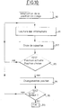
- an electronic control unit 63 is shown diagrammatically, connected at the input to a sensor 79 detecting the speed of the motor.
- Other operating parameter sensors can be connected to the unit 63 as already indicated.
- the information 81 emitted by the sensor 79 is received in a processor sensor interface 80 connected to a microprocessor 83 which, using an information processing program, sends signals to a processor interface purging means 85.
- the interface 85 sends control signals 86 and 87 in the form of electrical pulses to the solenoid valves EV1 and EV2 and to the adjustable throttles R1 and R2 of two respective tensioners T1 and T2.
- the signals 86 controlling the electrovalves EV1 and EV2 cause the passage of these from the open position to the closed position or vice versa.
- Signals 87 regulate the opening of variable throttles R1 and R2.
- the solenoid valve EV1 is open and the stroke of the tensioner T1 decreases according to a straight part of the corresponding curve, the slope of which is determined by the setting of the throttle variable R1 controlled by the control unit.
- the race becomes zero after a time equal to t3 - t1.
- the solenoid valve EV2 is closed, which causes the chamber 42 of the tensioner T2 to be pressurized and the output thereof as represented by a right-hand portion inclined on the curve corresponding, the slope of this part on the right being a function of the pressure build-up speed of the chamber 42.
- the soft strand is at this moment sufficiently relaxed to allow the tensioner T2 to come out.
- the action on the throttle R1 is such that T1 is returned before T2 is completely out (that is to say that t3 precedes t4).
- FIG. 9B shows the action of the control unit 63 of FIG. 8, this action being interrupted before time t3.
- the interruption is made at time t′5 which occurs after t2 but before time t3 in FIG. 9A which corresponds to the complete re-entry of the tensioner T1.
- the strokes of the T1 and T2 tensioners are both intermediate between the retracted position or the extended position and establish an intermediate offset between the initial offset and the maximum offset.
- the invention which has just been described uses a chain meshing on sprockets but the invention is also applicable to devices which use toothed belts and toothed pulleys as well as to devices which use smooth belts and smooth pulleys provided that 'There is no slippage between the belts and the pulleys.
Landscapes
- Engineering & Computer Science (AREA)
- General Engineering & Computer Science (AREA)
- Mechanical Engineering (AREA)
- Devices For Conveying Motion By Means Of Endless Flexible Members (AREA)
- Valve-Gear Or Valve Arrangements (AREA)
- Valve Device For Special Equipments (AREA)
- Supports For Plants (AREA)
Claims (11)
Applications Claiming Priority (2)
| Application Number | Priority Date | Filing Date | Title |
|---|---|---|---|
| FR8804956A FR2630178B1 (fr) | 1988-04-14 | 1988-04-14 | Dispositif de reglage du calage angulaire d'un arbre mene par rapport a un arbre menant |
| FR8804956 | 1988-04-14 |
Publications (2)
| Publication Number | Publication Date |
|---|---|
| EP0337894A1 EP0337894A1 (de) | 1989-10-18 |
| EP0337894B1 true EP0337894B1 (de) | 1992-06-17 |
Family
ID=9365317
Family Applications (1)
| Application Number | Title | Priority Date | Filing Date |
|---|---|---|---|
| EP89401043A Expired - Lifetime EP0337894B1 (de) | 1988-04-14 | 1989-04-14 | System zur Regelung des Differenzwinkels einer angetriebenen und einer antreibenden Welle |
Country Status (6)
| Country | Link |
|---|---|
| US (1) | US5159904A (de) |
| EP (1) | EP0337894B1 (de) |
| DE (1) | DE68901803T2 (de) |
| ES (1) | ES2032123T3 (de) |
| FR (1) | FR2630178B1 (de) |
| WO (1) | WO1993014302A1 (de) |
Cited By (1)
| Publication number | Priority date | Publication date | Assignee | Title |
|---|---|---|---|---|
| US9464697B2 (en) | 2011-09-05 | 2016-10-11 | Litens Automotive Partnership | Intelligent belt drive system and method |
Families Citing this family (24)
| Publication number | Priority date | Publication date | Assignee | Title |
|---|---|---|---|---|
| DE3939821A1 (de) * | 1989-12-01 | 1991-06-06 | Audi Ag | Spannvorrichtung fuer endlose antriebsmittel |
| DE4200509A1 (de) * | 1992-01-11 | 1993-07-15 | Porsche Ag | Nockenwellenantrieb einer mehrzylindrigen brennkraftmaschine |
| FR2763097B1 (fr) * | 1997-05-09 | 1999-09-03 | Vianney Paul Rabhi | Dispositif permettant de controler la position de la cremaillere de commande d'un moteur a cylindree variable |
| FR2763096B1 (fr) * | 1997-05-09 | 1999-07-30 | Vianney Paul Rabhi | Dispositif permettant de faire varier durant leur fonctionnement la cylindree et/ou le rapport volumetrique effectifs des moteurs a pistons |
| DE19804943A1 (de) * | 1998-02-07 | 1999-08-12 | Bosch Gmbh Robert | Brennkraftmaschine |
| JPH11230281A (ja) * | 1998-02-10 | 1999-08-27 | Honda Motor Co Ltd | テンショナの取付け構造 |
| GB9813961D0 (en) | 1998-06-30 | 1998-08-26 | Renold Plc | Method and apparatus for tensioning a chain of an internal combustion engine |
| FR2787540B1 (fr) * | 1998-12-22 | 2005-10-07 | Sachs Automotive France Sa | Tendeur hydraulique pour chaine ou lien sans fin pour l'equipement d'un moteur a combustion interne |
| DE19900499A1 (de) | 1999-01-08 | 2000-07-13 | Volkswagen Ag | Antriebe für Pumpe-Düse-Einspritzelemente oder Einspritzpumpen von Verbrennungsmotoren |
| US6106423A (en) * | 1999-04-05 | 2000-08-22 | Borgwarner Inc. | Dual tensioner system for balance shaft drive |
| US6572501B2 (en) * | 1999-04-29 | 2003-06-03 | Gerhard Winklhofer | Method and device for reducing vibrations of a control chain in a camshaft drive of an internal combustion engine |
| DE19943917A1 (de) * | 1999-09-14 | 2001-03-15 | Volkswagen Ag | Verfahren zur Überwachung des Verschleißes eines mit einem Zahnriemen ausgestatteten Nockenwellenantriebes |
| KR20030017870A (ko) * | 2001-08-23 | 2003-03-04 | 현대자동차주식회사 | 가변 배기밸브 타이밍 컨트롤 장치 |
| US6652401B2 (en) * | 2002-02-11 | 2003-11-25 | The Gates Corporation | Method of tuning a belt drive system |
| DE102004028017A1 (de) * | 2004-06-08 | 2005-12-29 | Bayerische Motoren Werke Ag | Zugmittelanordnung |
| WO2006047099A2 (en) | 2004-10-26 | 2006-05-04 | George Louie | Continuously variable valve timing device |
| US20090186726A1 (en) * | 2008-01-22 | 2009-07-23 | Gm Global Technology Operations, Inc. | Belted alternator starter accessory drive tensioning system |
| EP2707625B1 (de) * | 2011-05-13 | 2019-09-25 | Litens Automotive Partnership | Intelligentes bandantriebssystem und entsprechendes verfahren |
| WO2013159181A1 (en) * | 2012-04-28 | 2013-10-31 | Litens Automotive Partnership | Adjustable tensioner |
| DE102012217206A1 (de) * | 2012-09-24 | 2014-03-27 | Schaeffler Technologies Gmbh & Co. Kg | Spannvorrichtung für einen Zugmitteltrieb |
| KR101405235B1 (ko) * | 2013-07-18 | 2014-06-19 | 현대자동차 주식회사 | 유압식 타이밍 체인 텐셔너 및 타이밍 체인 장치 |
| DE102013224457A1 (de) * | 2013-11-28 | 2015-05-28 | Schaeffler Technologies AG & Co. KG | Geregelte hydraulische Spannvorrichtung |
| JP6256505B2 (ja) * | 2016-03-17 | 2018-01-10 | マツダ株式会社 | エンジンの補機駆動装置 |
| FR3131356B1 (fr) * | 2021-12-23 | 2024-02-16 | Commissariat Energie Atomique | dispositif et procédé de transmission de mouvement, robot et véhicule automobile équipés d’un tel dispositif |
Citations (1)
| Publication number | Priority date | Publication date | Assignee | Title |
|---|---|---|---|---|
| EP0195945A1 (de) * | 1985-02-26 | 1986-10-01 | Joh. Winklhofer & Söhne | Kettenspanner |
Family Cites Families (12)
| Publication number | Priority date | Publication date | Assignee | Title |
|---|---|---|---|---|
| DE1964005A1 (de) * | 1969-12-20 | 1971-06-24 | Wilfried Koelker | Stufenloses Regeln der OEffnungszeiten und OEffnungswinkel von Gaswechsel-Ventilen,besonders bei Viertakt-Brennkraftmaschinen |
| US3888217A (en) * | 1973-09-24 | 1975-06-10 | Charles A Hisserich | Camshaft belt drive for variable valve timing |
| JPS56143850A (en) * | 1980-04-09 | 1981-11-09 | Nippon Soken Inc | Belt tension control device |
| JPS57161344A (en) * | 1981-03-27 | 1982-10-04 | Nippon Denso Co Ltd | Belt tension control device |
| JPS57173651A (en) * | 1981-04-20 | 1982-10-26 | Nissan Motor Co Ltd | Automatic belt tension control device |
| JPS5963338A (ja) * | 1982-10-04 | 1984-04-11 | Toyota Motor Corp | バルブタイミング可変式内燃機関の切替タイミング制御方法 |
| JPS5979046A (ja) * | 1982-10-28 | 1984-05-08 | Hino Motors Ltd | デイ−ゼル機関に使用される燃料噴射装置 |
| CH651109A5 (en) * | 1982-12-21 | 1985-08-30 | Pierre Chatelain | Device intended to vary the timing setting of a combustion engine |
| DE3506107A1 (de) * | 1984-02-22 | 1985-08-22 | Audi AG, 8070 Ingolstadt | Verfahren zur verbesserten abgasentgiftung einer ventilgesteuerten brennkraftmaschine |
| DE3509094A1 (de) * | 1984-04-06 | 1985-10-17 | Volkswagenwerk Ag, 3180 Wolfsburg | Einrichtung zum stufenlosen verstellen der steuerzeiten von gaswechselventilen |
| JP2610121B2 (ja) * | 1985-05-14 | 1997-05-14 | ヤマハ発動機株式会社 | 内燃機関の開弁時期調節装置 |
| FR2610685B1 (fr) * | 1987-02-09 | 1991-01-25 | Sedis Transmissions Mec | Tendeur a commande hydraulique, notamment pour chaine |
-
1988
- 1988-04-14 FR FR8804956A patent/FR2630178B1/fr not_active Expired - Fee Related
-
1989
- 1989-04-14 EP EP89401043A patent/EP0337894B1/de not_active Expired - Lifetime
- 1989-04-14 US US07/458,742 patent/US5159904A/en not_active Expired - Fee Related
- 1989-04-14 ES ES198989401043T patent/ES2032123T3/es not_active Expired - Lifetime
- 1989-04-14 DE DE8989401043T patent/DE68901803T2/de not_active Expired - Fee Related
- 1989-04-14 WO PCT/FR1989/000170 patent/WO1993014302A1/fr not_active Ceased
Patent Citations (1)
| Publication number | Priority date | Publication date | Assignee | Title |
|---|---|---|---|---|
| EP0195945A1 (de) * | 1985-02-26 | 1986-10-01 | Joh. Winklhofer & Söhne | Kettenspanner |
Cited By (1)
| Publication number | Priority date | Publication date | Assignee | Title |
|---|---|---|---|---|
| US9464697B2 (en) | 2011-09-05 | 2016-10-11 | Litens Automotive Partnership | Intelligent belt drive system and method |
Also Published As
| Publication number | Publication date |
|---|---|
| DE68901803T2 (de) | 1993-01-07 |
| FR2630178B1 (fr) | 1993-02-05 |
| FR2630178A1 (fr) | 1989-10-20 |
| US5159904A (en) | 1992-11-03 |
| ES2032123T3 (es) | 1993-01-01 |
| DE68901803D1 (de) | 1992-07-23 |
| WO1993014302A1 (fr) | 1993-07-22 |
| EP0337894A1 (de) | 1989-10-18 |
Similar Documents
| Publication | Publication Date | Title |
|---|---|---|
| EP0337894B1 (de) | System zur Regelung des Differenzwinkels einer angetriebenen und einer antreibenden Welle | |
| FR2636108A1 (fr) | Dispositif pour regler la position angulaire relative de deux arbres relies selon une liaison motrice | |
| FR2461108A1 (fr) | Mecanisme de commande de soupape pour moteurs a combustion interne | |
| FR2867248A1 (fr) | Transmission variable en continu a courroie destinee a un vehicule | |
| FR2461807A1 (fr) | Dispositif pour la regulation, au moyen d'un tiroir plat, du remplissage des cylindres dans des moteurs a combustion interne | |
| FR2678341A1 (fr) | Boite de vitesses a reglage continu, et plus particulierement son servomecanisme secondaire a double effet. | |
| FR2777942A1 (fr) | Dispositif perfectionne d'actionnement de soupapes de distribution variable pour moteurs a combustion interne | |
| EP1471232B1 (de) | Verfahren zur Ventilsteuerung in einer Brennkraftmaschine | |
| FR2468732A1 (fr) | Distribution variable a commande hydraulique pour moteurs a combustion interne | |
| FR2846369A1 (fr) | Moteur de type a taux de compression variable | |
| FR2608684A1 (fr) | Pompe d'injection de carburant pour moteur a combustion interne avec coupure par etranglement sur le canal de decharge, en fonction de la charge | |
| FR2731251A1 (fr) | Dispositif de commande de synchronisation a soupape | |
| EP1039116A1 (de) | Verfahren zur Steuerung einer Brennkraftmaschine | |
| EP0063523A1 (de) | Einspritzpumpe für Brennkraftmaschinen mit einer Regeleinrichtung zum Steuern des Kraftstofförderzeitpunkts | |
| FR2989120A1 (fr) | Appareil d'admission d'air pour moteur a combustion interne | |
| FR2519085A1 (fr) | Dispositif d'injection de combustible pour moteurs a combustion interne | |
| FR2752441A1 (fr) | Dispositif et procede de commande d'un actionneur, notamment pour faire fonctionner les soupapes d'un moteur a combustion interne | |
| BE400981A (de) | ||
| JP2786257B2 (ja) | 動弁機構のバルブタイミング調整装置 | |
| WO2005024191A2 (fr) | Dispositif de commande hydraulique d'ouverture de soupapes de moteurs à combustion interne | |
| FR2774724A1 (fr) | Moteur a combustion interne | |
| BE499366A (de) | ||
| EP1937983A1 (de) | Ventil mit gedämpftem öffnungssystem | |
| FR2596455A1 (fr) | Commande de soupape pour moteurs diesel a combustion interne | |
| EP0688944A1 (de) | Zweitaktbrennkraftmaschine |
Legal Events
| Date | Code | Title | Description |
|---|---|---|---|
| PUAI | Public reference made under article 153(3) epc to a published international application that has entered the european phase |
Free format text: ORIGINAL CODE: 0009012 |
|
| AK | Designated contracting states |
Kind code of ref document: A1 Designated state(s): DE ES FR GB IT |
|
| 17P | Request for examination filed |
Effective date: 19891009 |
|
| 17Q | First examination report despatched |
Effective date: 19901218 |
|
| GRAA | (expected) grant |
Free format text: ORIGINAL CODE: 0009210 |
|
| AK | Designated contracting states |
Kind code of ref document: B1 Designated state(s): DE ES FR GB IT |
|
| GBT | Gb: translation of ep patent filed (gb section 77(6)(a)/1977) | ||
| REF | Corresponds to: |
Ref document number: 68901803 Country of ref document: DE Date of ref document: 19920723 |
|
| ITF | It: translation for a ep patent filed | ||
| REG | Reference to a national code |
Ref country code: ES Ref legal event code: FG2A Ref document number: 2032123 Country of ref document: ES Kind code of ref document: T3 |
|
| PLBE | No opposition filed within time limit |
Free format text: ORIGINAL CODE: 0009261 |
|
| STAA | Information on the status of an ep patent application or granted ep patent |
Free format text: STATUS: NO OPPOSITION FILED WITHIN TIME LIMIT |
|
| 26N | No opposition filed | ||
| PGFP | Annual fee paid to national office [announced via postgrant information from national office to epo] |
Ref country code: DE Payment date: 19980319 Year of fee payment: 10 |
|
| PGFP | Annual fee paid to national office [announced via postgrant information from national office to epo] |
Ref country code: ES Payment date: 19980401 Year of fee payment: 10 |
|
| PGFP | Annual fee paid to national office [announced via postgrant information from national office to epo] |
Ref country code: GB Payment date: 19980407 Year of fee payment: 10 |
|
| PGFP | Annual fee paid to national office [announced via postgrant information from national office to epo] |
Ref country code: FR Payment date: 19980428 Year of fee payment: 10 |
|
| PG25 | Lapsed in a contracting state [announced via postgrant information from national office to epo] |
Ref country code: GB Free format text: LAPSE BECAUSE OF NON-PAYMENT OF DUE FEES Effective date: 19990414 |
|
| PG25 | Lapsed in a contracting state [announced via postgrant information from national office to epo] |
Ref country code: ES Free format text: LAPSE BECAUSE OF NON-PAYMENT OF DUE FEES Effective date: 19990415 |
|
| GBPC | Gb: european patent ceased through non-payment of renewal fee |
Effective date: 19990414 |
|
| PG25 | Lapsed in a contracting state [announced via postgrant information from national office to epo] |
Ref country code: FR Free format text: LAPSE BECAUSE OF NON-PAYMENT OF DUE FEES Effective date: 19991231 |
|
| REG | Reference to a national code |
Ref country code: FR Ref legal event code: ST |
|
| PG25 | Lapsed in a contracting state [announced via postgrant information from national office to epo] |
Ref country code: DE Free format text: LAPSE BECAUSE OF NON-PAYMENT OF DUE FEES Effective date: 20000201 |
|
| REG | Reference to a national code |
Ref country code: ES Ref legal event code: FD2A Effective date: 20010503 |
|
| PG25 | Lapsed in a contracting state [announced via postgrant information from national office to epo] |
Ref country code: IT Free format text: LAPSE BECAUSE OF NON-PAYMENT OF DUE FEES;WARNING: LAPSES OF ITALIAN PATENTS WITH EFFECTIVE DATE BEFORE 2007 MAY HAVE OCCURRED AT ANY TIME BEFORE 2007. THE CORRECT EFFECTIVE DATE MAY BE DIFFERENT FROM THE ONE RECORDED. Effective date: 20050414 |