EP0337475A2 - Pfahlrammanlage - Google Patents
Pfahlrammanlage Download PDFInfo
- Publication number
- EP0337475A2 EP0337475A2 EP89106670A EP89106670A EP0337475A2 EP 0337475 A2 EP0337475 A2 EP 0337475A2 EP 89106670 A EP89106670 A EP 89106670A EP 89106670 A EP89106670 A EP 89106670A EP 0337475 A2 EP0337475 A2 EP 0337475A2
- Authority
- EP
- European Patent Office
- Prior art keywords
- pile
- column
- jack
- driving apparatus
- pile driving
- Prior art date
- Legal status (The legal status is an assumption and is not a legal conclusion. Google has not performed a legal analysis and makes no representation as to the accuracy of the status listed.)
- Granted
Links
Images


Classifications
-
- E—FIXED CONSTRUCTIONS
- E02—HYDRAULIC ENGINEERING; FOUNDATIONS; SOIL SHIFTING
- E02D—FOUNDATIONS; EXCAVATIONS; EMBANKMENTS; UNDERGROUND OR UNDERWATER STRUCTURES
- E02D7/00—Methods or apparatus for placing sheet pile bulkheads, piles, mouldpipes, or other moulds
- E02D7/02—Placing by driving
- E02D7/06—Power-driven drivers
- E02D7/14—Components for drivers inasmuch as not specially for a specific driver construction
- E02D7/16—Scaffolds or supports for drivers
Definitions
- This invention relates to pile driving apparatus, in particular to jack piling systems.
- Jack piling apparatuses are usually confined to situations where piles must be driven into the ground and no significant vibration and noise is permitted.
- pile driving apparatuses have been proposed in the past. Several are discussed in "Pile Design and Construction Practice", third edition by M J Tomlinson, published in 1987.
- Previously used jack piling apparatuses employ the use of a jack which bears down directly onto the top of the pile to be driven into the ground. These systems are frequently referred to as "jack-in piling systems”. These systems are mainly used for underpinning foundations, but owing to their relative complexity, are not competitive with conventional piling systems and so are seldom used in new pile foundation works.
- One previously used jack piling apparatus involves inserting a jack betveen the foundations to be underpinned and the top of the pile to be driven into the ground.
- the foundations themselves provide the reaction force to the jacking.
- Such jack-in piling systems can only install two pile positions per working day. This makes such jack-in piling systems uneconomical for extensive use even in the present pile foundation market.
- a pile driving apparatus comprising: jack means for exerting a pile driving force in one direction onto a pile to be driven via transmission means; and reaction means for providing a reaction force to the pile driving force; wherein the longitudinal axis of the pile lies substantially parallel to but spaced apart from the one direction, and the transmission means is configured to transmit the driving force from the one direction to the pile thereby enabling at least a part of the jack means to extend alongside the pile.
- the pile driving apparatus preferably includes a column for receiving the pile along its length on one side thereof, the length of the pile substantially corresponding to the length of the column.
- the jack means may be fixed to one end of the column on the side of the column which is opposite from the side receiving the pile.
- the transmission means may comprise a first thrust member for receiving a piston of the jack means, a second thrust member for urging against the free end of the pile, and a transmission member which links the first and second thrust members via an aperture extending along the length of the column.
- the piston of the jack means is preferably capable of pushing the first thrust member along substantially half of the length of the column in a single stroke, thereby permitting driving of the pile in two strokes of the jack means.
- a base frame is attached towards the lower end of the column, and comprises support means for supporting the apparatus, and levelling means for levelling the base and ensuring the column is at least substantially vertical.
- the base frame is preferably arranged to support ballast or Kentledge for providing the reaction force to the pile driving force, the reaction force being transmitted between the ballast or Kentledge and the jack means via the column.
- the column may be in the form of a steal "H" cross-sectional column.
- a base frame for a jack piling apparatus comprising support means for supporting a pile to be driven into the ground, and supporting a jack means for driving the pile into the ground, and for supporting ballast or Kentledge for providing a reaction force to the jack means, wherein the base frame includes levelling jacks operative to adjust the base frame so that the pile can be made to be substantially vertical.
- the base frame is constructed so as to be sufficiently stiff to resist distortions due to the reaction force which occurs during pile driving.
- a pile loading device for loading piles into a pile driving apparatus, the pile loading device comprising an elongate cradle which is pivotally connectable to the apparatus so that the cradle can be moved between horizontal and vertical positions, and a jack for moving the cradle about the pivotal point, wherein the cradle is configured to receive a pile when in the horizontal position, and to be moved into a vertical position by means of the jack thereby enabling positioning of the pile for driving into the ground.
- the loading device is preferably provided with means for guiding the end of the pile closest to the pivotal end of the cradle for locating it with the exposed end of the previously driven pile.
- the pile loading device is also configured for placing a dolly onto a partially driven pile.
- the guiding means may be adjustable to accommodate different pile profiles.
- the pile loading device and/or base frame may be incorporated into the pile driving apparatus as defined hereinbefore.
- Embodiments of the invention may include a jointing apparatus for connecting adjacent piles end to end, and for restraining relative movement between the piles in the 3 degrees of rotational motion, and the 3 degrees of translational motion.
- a jointing apparatus preferably comprises a plate having a cross-section corresponding substantially to that of the pile to be driven, bonding means extending from one side of the plate around which the pile is cast thereby enabling bonding of the plate to the pile, and a channel formed in the plane of the plate and for receiving a leg of a substantially "C” or "U” shaped clip such that there can be no relative movement between the clip and the plate.
- the other leg of the clip can be received by a corresponding ressess of a corresponding plate cast into another pile. Positioning of the plate clip in this way joins the piles and prevents relative movement therebetween.
- a plurality of channels may be formed in end plate for receiving a corresponding number of clips thereby providing extra security against relative movement between adjacent piles.
- the pile driving apparatus of the present invention which may include the base frame and/or the pile loading device, may be suspended from or attached to a mobile crane.
- the apparatus may be mounted onto a mobile base machine which has sufficient weight to provide the reaction force as shown in Fig. 5.
- Embodiments of the present invention provide significant advantages over previously used jack-in pile driving systems.
- a significant advantage is afforded by the pile driving apparatus of the present invention owing to the indirect application of the driving force from the jack means to the pile.
- Embodiments of the present invention thereby enable longer jacking strokes and a faster piling extension procedure.
- Embodiments of the invention can install about 20 pile positions in a working day.
- Embodiments of the present invention are therefore cost competitive with other existing pile systems which are not generally designed for underpinning works. Moreover, embodiments of the present invention do not preclude the use of twin or multiple hydraulic jack assemblies for providing the pile driving force.
- Embodiments of the present invention may be used for pre-stressed concrete pile elements of various cross-sectional shapes, for example, triangular, "V" shaped square, round, hexagonal or tubular.
- Pre-stressed concrete pile elements are preferably pre-tensioned using a single pre-stressing wire along the central longitudinal axis of the pile. Several pre-stressing wires can also be used. Piles of 125 mm to 225 mm in lateral dimension may be used.
- Embodiments of the invention enable use of pre-stressed concrete pile elements having effective pre-stress of less than 2 MPa. Piles made of other materials such as timber or steel may also be driven into the ground using embodiments of the present invention. Lengths of pile elements may, for example be between 3 and 6 metres long.
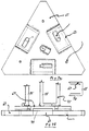
- Figures 1 and 2 illustrate an embodiment of the invention which comprises a base frame 1 having a platform 3 for supporting ballast or Kentledge 5.
- the base frame 1 is preferably constructed of steel sections or steel plates which are sufficiently stiff to prevent any significant distortions occurring when the reaction force is applied during pile installation.
- the base frame 1 is equipped with a levelling device in the form of jacks 7 positioned at each corner thereof.
- Each jack 7 can be adjusted independently of one another so as to ensure that the base frame lies substantially horizontally, and in particular, to ensure that a pile 8 (see Figure 3) to be driven into the ground is vertical with respect to the ground.
- the Kentledge or ballast may be weights totalling 40 tonnes.
- One 10 tonne weight 9 may be positioned at each corner of the base frame 1 above a jack 7.
- the pile driving apparatus comprises a column 11 positioned substantially perpendicular with respect to the base frame 1, and supported in position by means of steel supports 13. Bracing members 15 are provided on the base frame 1 in order to enhance the stiffness of the apparatus.
- the column 11 will be described in detail below with reference to Figures 3 and 4.
- a lifting point 17 which can be attached to the hook of, for example, a mobile crane thereby enabling positioning of the apparatus.
- the apparatus includes a pile loading device which consists of a cradle arm 19 which is pivotally mounted at point 21 to the base frame 1, at the lower end of the column 11.
- a hydraulic jack 23 is positioned on the base frame 1 and comprises a hydraulic piston 25 which is connected to the cradle arm 19. The operation of the cradle arm will be discussed below.
- FIGS 3 and 4 illustrate the column 11 of the pile driving apparatus in more detail.
- the column 11 is constructed of a steel "H" profiled column which is of sufficient strength to transmit the reaction force from a jack means to the Kentledge.
- the jack means is in the form of a hydraulic cylinder 27 and a hydraulic piston 29.
- the hydraulic cylinder 27 is fixedly attached to the top end of one side of the column 11. This side of the column 11 forms a hydraulic jack compartment of the pile driving apparatus.
- the other side of the column 11 forms the pile compartment 31 of the pile driving apparatus.
- the pile compartment 31 receives the pile 8 for driving into the ground.
- a transmission means transmits the pile driving force from the hydraulic cylinder 27 to the pile 8 contained in the pile compartment 31.
- the transmission means comprises a jack thrust plate 33 onto which the driving load of the hydraulic piston 29 bears.
- the jack thrust plate 33 is rigidly connected to a transmission plate 35 by means of a shear plate 37 which is welded onto the transmission plate.
- the higher end of the transmission plate 35 is rigidly connected to a pile thrust plate 39 by means of another shear plate 41.
- the web portion 43 of the column 11 is provided with an elongate slit running along the longitudinal length thereof for accommodating the transmission plate 35 and for permitting the transmission plate to move along the length of the column 11.
- the configuration of transmission means is such that the hydraulic cylinder 27 and the hydraulic piston 29 can extend alongside the pile to be driven into the ground. Consequently, piles having a length substantially corresponding to the height of the column 11 may be driven into the ground with embodiments of the present invention.
- stiffener plates 45 are welded along the length of the web portion 43 of the column 11.
- a channel section 47 which acts as a guide for the transmission plate 35.
- the channel section 47 also reduces the possibility of the transmission means twisting within the slit formed in the web portion 43.
- the pile thrust plate 39 has a cross-section which corresponds to the cross-section of the pile 8. This thrust plate 39 makes contact with the pile to be driven into the ground.
- the hydraulic piston 29 is capable of extending to substantially half the length of the pile 8, thereby driving half the length of the pile into the ground in one stroke.
- This embodiment is provided with the pile loading device which comprises the cradle arm 19 which is pivotally mounted at the point 21 to the base frame 1 at the lower end of the column 11.
- the operation of the pile loading device is as follows.
- the cradle arm 19 is lowered, by means of the hydraulic jack 23 and piston 25, into a horizontal position as illustrated in Figure 2.
- the pile element 8 is then lifted and placed horizontally onto the cradle arm 19 either manually or by crane.
- the hydraulic jack piston 25 then retracts causing the cradle arm 19 to swing into a vertical position together with the pile element to be loaded into the pile compartment 31 of the column 11.
- a guide 49 is provided on the cradle arm 19 which ensures that the lowermost end of the pile element is correctly located above the correct position on the ground, or if the pile element is an extension pile, the adapter 49 ensures that the lowermost end of the pile extension accurately locates with the top of the pile element already driven into the ground.
- the guide 49 may be adjusted to accommodate piles of different profiles and sizes.
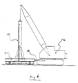
- Figure 5 illustrates the pile driving apparatus of the present embodiment mounted on a mobile base machine 50.
- the pile driving apparatus may be transported by the mobile base machine 50 as illustrated in Figure 5.
- the column 11 is supported on the mobile base machine 50 by means of a steel hollow section column 51 which is pivotally supported at a point 53 of the mobile base machine 50.
- the pile driving apparatus can be deployed by means of the hydraulic arm 55. During deployment, the mobile base machine 50 can be stabilized by means of a stability jack 57.
- Figure 6 illustrates the pile driving apparatus mounted on a static base frame which is positioned using a mobile crane 52.
- the mobile crane also loads the Kentledge onto the base frame.
- the column 11 is suspended from the mobile crane 52 by means of a hook attached to the lifting point 17 of the column 11.
- the horizontal positioning of the base frame 1 can be controlled by means of a position control attachment 59 which can be controlled by the mobile crane 52.
- the mobile base machine or crane may be capable of lifting a 10 tonne load.
- the bearing capacity of the pile may be 16 tonnes working load, and the pile length per element may be 5 metres.
- the column 11 and base frame 1 are first lifted into place and positioned over the desired location.
- the four 10 tonne Kentledge pieces are then lifted and placed into position on the base frame 1 to form the Kentledge. Levelling of the base frame 1 can then take place in order to ensure that the column 11 is vertical.
- the cradle arm 19 is lowered to the horizontal position in order to receive the pile element.
- the hydraulic jack 23 and 25 then lifts the cradle arm 19 and pile element into the pile compartment 31, and the pile thrust plate 39 is located on the top end of the pile.
- the hydraulic cylinder and piston 27 and 29 can then drive the pile element, via the indirect jacking force method of the invention until, for example, half of the pile element is driven into the ground.
- the hydraulic piston 29 can then be retracted to its original position when the loading of the pile took place.
- the cradle arm 19 is again lowered to the horizontal position in order to receive a steel dolly.
- the cradle arm 19 then lifts the dolly (not shown) into the pile compartment 31 with the dolly end resting flat on the half embedded pile element.
- the hydraulic piston 29 is then activated again and the dolly pushes the remaining half of the pile element downwards.
- the cradle arm 19 can then be used to remove the dolly and further extension pile elements can then be driven into the ground using the above procedure.
- any pile elements protruding from the ground can be cut by means of an appropriate special cutter.
- the Kentledge can then be unloaded from the base frame and the apparatus then lifted to another pile position for repeat procedures.
- Adjacent ends of extension piles may be connected together by means of the "clip in" jointing system of the present invention.
- An example of such a jointing system will be described below.
- FIGS. 7a and 7b illustrate an embodiment of clip-in jointing system according to the present invention.
- the jointing assembly comprises a substantially "V"-shaped or triangular shaped plate 61 having the same cross-section as the pile element to be driven into the ground.
- a recess 63 is formed on each of the three sides of the plate 61 for receiving a linking portion 65 of a substantially "U” or “C” shaped clip 67.
- a plate 69 is welded to the plate 61 at each of the recess points 63, and provides a channel 71 or hole for receiving a leg 73 of the clip 67.
- a bonding bar 75 is welded to each of the plates 69.
- the end of the concrete pile is cast around the bonding bars 75 thereby securely bonding the plate 61 to the pile element.
- Tensile stress resultants are transferred from the concrete pile element to the bonding bars 75 by interface bond. These stresses are in turn transferred through the channel shaped plate 69 and the V-shaped or triangular shaped plate 61 which have been welded to the bonding bars 75. Through contact stresses, the tensile stress resultants are transferred via the clip 67 to the adjacent pile end of similar construction.
- the two legs 73 of the clip 67 can be simply and easily inserted into the channels 71.
- the clip 67 is slightly profiled during manufacture to provide a slight interference or press fit during insertion at the joint.
- Three or more clips 67 are positioned in order to rigidly secure the pile end together thereby restraining relative movement therebetween in each of the 6 degrees of freedom (ie 3 rotations and 3 translations).
- moderate side dimensions of piles may be employed, for example, 100 mm to 200 mm, whereas in established systems 300 mm2 precast concrete piles are used.
- embodiments of the invention enable Kentledge to be placed on a mobile machine or on the base frame of the apparatus itself.
- the Kentledge can easily be moved to a new position where required, and is not restricted to the position of the existing foundations.
- Embodiments of the invention are also advantageous in that they permit a long stroke of the jack, for example, 1.5 to 4 metres thereby enabling an entire pile element to be installed in two strokes.
- conventional systems have a short jack stroke of, for example, 0.25 metres thereby requiring a multiple number of strokes required to install a single pile element.
- Embodiments of the invention may incorporate the clip-in jointing system described hereinabove which enables the joints of adjacent piles to be established speedily. This contrasts with prior art arrangements wherein precast concrete elements are bonded together by inserting short steel bars into the longitudinal central hole, and subsequently grouting them with cement.
- Embodiments of the present invention enable full use of the available headroom, the headroom corresponding substantially to the length of each pile element to be used.
- a 3 metre length of pile element may be installed in the headroom of only 3.1 metres.
- a working headroom of about 1.8 metres enables installation of only a 1.2 metre length of open-ended steel tube.
- Embodiments of the invention also enable the use of twin or multiple hydraulic jacks to be used for providing the jacking force.
Landscapes
- Engineering & Computer Science (AREA)
- Life Sciences & Earth Sciences (AREA)
- General Life Sciences & Earth Sciences (AREA)
- Mining & Mineral Resources (AREA)
- Paleontology (AREA)
- Civil Engineering (AREA)
- General Engineering & Computer Science (AREA)
- Structural Engineering (AREA)
- Placing Or Removing Of Piles Or Sheet Piles, Or Accessories Thereof (AREA)
- Piles And Underground Anchors (AREA)
Applications Claiming Priority (2)
| Application Number | Priority Date | Filing Date | Title |
|---|---|---|---|
| GB8808988 | 1988-04-15 | ||
| GB8808988A GB2217366B (en) | 1988-04-15 | 1988-04-15 | Pile driving apparatus |
Publications (3)
| Publication Number | Publication Date |
|---|---|
| EP0337475A2 true EP0337475A2 (de) | 1989-10-18 |
| EP0337475A3 EP0337475A3 (en) | 1990-04-25 |
| EP0337475B1 EP0337475B1 (de) | 1995-02-22 |
Family
ID=10635286
Family Applications (1)
| Application Number | Title | Priority Date | Filing Date |
|---|---|---|---|
| EP89106670A Expired - Lifetime EP0337475B1 (de) | 1988-04-15 | 1989-04-14 | Pfahlrammanlage |
Country Status (11)
| Country | Link |
|---|---|
| EP (1) | EP0337475B1 (de) |
| KR (1) | KR0160117B1 (de) |
| CN (1) | CN1019323B (de) |
| AU (1) | AU626088B2 (de) |
| CA (2) | CA1336545C (de) |
| DE (1) | DE68921231T2 (de) |
| GB (1) | GB2217366B (de) |
| HK (1) | HK126393A (de) |
| IN (1) | IN175125B (de) |
| MY (1) | MY103708A (de) |
| NZ (1) | NZ228740A (de) |
Cited By (3)
| Publication number | Priority date | Publication date | Assignee | Title |
|---|---|---|---|---|
| AU785079B2 (en) * | 2002-03-15 | 2006-09-14 | Ho Choon Aw | Stone column construction for ground improvement |
| CN115324051A (zh) * | 2022-04-13 | 2022-11-11 | 中交第一航务工程局有限公司 | 灌注桩钻机配套用多功能辅助机架 |
| CN120443645A (zh) * | 2025-07-09 | 2025-08-08 | 杭州圣基建筑特种工程有限公司 | 一种液压静力自动压桩机 |
Families Citing this family (7)
| Publication number | Priority date | Publication date | Assignee | Title |
|---|---|---|---|---|
| GB2248082B (en) * | 1990-09-18 | 1994-11-16 | Concilink | Pile driving |
| GB2260776A (en) * | 1991-10-25 | 1993-04-28 | Sum Cheong Machinery Pte Ltd | Pile driving apparatus |
| CN1034750C (zh) * | 1992-09-11 | 1997-04-30 | 管明德 | 锚梁式静压桩法及其压桩专用设备 |
| GB9724024D0 (en) | 1997-11-13 | 1998-01-14 | Kvaerner Cementation Found Ltd | Improved piling method |
| RU2158804C1 (ru) * | 2000-03-27 | 2000-11-10 | Литвин Олег Владимирович | Установка для погружения свай или шпунта |
| HK1027264A2 (en) * | 2000-08-11 | 2000-12-15 | 萧树棠 | Hydrostatic pressure ramming machine |
| AT509461B1 (de) * | 2010-09-27 | 2011-09-15 | Plasser Bahnbaumasch Franz | Stopfmaschine |
Family Cites Families (6)
| Publication number | Priority date | Publication date | Assignee | Title |
|---|---|---|---|---|
| GB1161796A (en) * | 1966-09-01 | 1969-08-20 | Philip Wilson Turner | Improvements in and relating to Pile Drivers. |
| JPS539001B2 (de) * | 1973-05-18 | 1978-04-03 | ||
| NL7704669A (nl) * | 1976-06-01 | 1977-12-05 | Hanebeck Bau Gmbh | Inrichting voor het geluidloos indrijven van damwandplanken en dergelijke bouwdelen. |
| NL7800182A (nl) * | 1978-01-06 | 1979-07-10 | Ballast Nedam Groep Nv | Werkwijze voor het in de grond brengen van een betonnen paal. |
| GB2028902B (en) * | 1978-08-29 | 1982-08-11 | Spence D | Hydraulically powered attachment for a tractor |
| US4555090A (en) * | 1983-09-23 | 1985-11-26 | Averhoff Wil W | Fence post driving and pulling apparatus |
-
1988
- 1988-04-15 GB GB8808988A patent/GB2217366B/en not_active Expired - Fee Related
-
1989
- 1989-04-13 NZ NZ228740A patent/NZ228740A/en unknown
- 1989-04-14 AU AU33038/89A patent/AU626088B2/en not_active Ceased
- 1989-04-14 EP EP89106670A patent/EP0337475B1/de not_active Expired - Lifetime
- 1989-04-14 CA CA000596736A patent/CA1336545C/en not_active Expired - Fee Related
- 1989-04-14 DE DE68921231T patent/DE68921231T2/de not_active Expired - Fee Related
- 1989-04-15 KR KR1019890004995A patent/KR0160117B1/ko not_active Expired - Fee Related
- 1989-04-15 CN CN89102292A patent/CN1019323B/zh not_active Expired
- 1989-04-15 MY MYPI89000488A patent/MY103708A/en unknown
- 1989-04-17 IN IN341DE1989 patent/IN175125B/en unknown
-
1993
- 1993-11-18 HK HK1263/93A patent/HK126393A/xx not_active IP Right Cessation
-
1995
- 1995-05-08 CA CA000616999A patent/CA1339457C/en not_active Expired - Fee Related
Cited By (4)
| Publication number | Priority date | Publication date | Assignee | Title |
|---|---|---|---|---|
| AU785079B2 (en) * | 2002-03-15 | 2006-09-14 | Ho Choon Aw | Stone column construction for ground improvement |
| CN115324051A (zh) * | 2022-04-13 | 2022-11-11 | 中交第一航务工程局有限公司 | 灌注桩钻机配套用多功能辅助机架 |
| CN115324051B (zh) * | 2022-04-13 | 2024-05-07 | 中交第一航务工程局有限公司 | 灌注桩钻机配套用多功能辅助机架 |
| CN120443645A (zh) * | 2025-07-09 | 2025-08-08 | 杭州圣基建筑特种工程有限公司 | 一种液压静力自动压桩机 |
Also Published As
| Publication number | Publication date |
|---|---|
| AU3303889A (en) | 1989-10-19 |
| NZ228740A (en) | 1992-03-26 |
| HK126393A (en) | 1993-11-26 |
| CA1336545C (en) | 1995-08-08 |
| MY103708A (en) | 1993-08-28 |
| AU626088B2 (en) | 1992-07-23 |
| GB2217366B (en) | 1992-05-06 |
| EP0337475A3 (en) | 1990-04-25 |
| CN1019323B (zh) | 1992-12-02 |
| CN1037941A (zh) | 1989-12-13 |
| GB2217366A (en) | 1989-10-25 |
| CA1339457C (en) | 1997-09-16 |
| KR900016550A (ko) | 1990-11-13 |
| EP0337475B1 (de) | 1995-02-22 |
| KR0160117B1 (ko) | 1999-01-15 |
| IN175125B (de) | 1995-04-29 |
| DE68921231D1 (de) | 1995-03-30 |
| DE68921231T2 (de) | 1995-07-13 |
| GB8808988D0 (en) | 1988-05-18 |
Similar Documents
| Publication | Publication Date | Title |
|---|---|---|
| US5246311A (en) | Foundation repairing system | |
| US5492437A (en) | Self-aligning devices and methods for lifting and securing structures | |
| US5733068A (en) | Metal foundation push-it and installation apparatus and method | |
| US5951206A (en) | Foundation lifting and support system and method | |
| US4925345A (en) | Building foundation stabilizing and elevating apparatus | |
| CA2365069C (en) | Building foundation installation system | |
| US6352390B1 (en) | Apparatus for lifting and supporting a foundation under tension and compression | |
| US6872031B2 (en) | Apparatus and method of supporting a structure with a pier | |
| US6468002B1 (en) | Foundation supporting and lifting system and method | |
| US5161625A (en) | Pile driving apparatus | |
| CA1336545C (en) | Pile driving apparatus | |
| EP1456480A1 (de) | Segmentierter spreizanker und verfahren zur einbringung ins erdreich zur erstellung einer gründung | |
| US4989677A (en) | Pile driving | |
| US6390734B1 (en) | Method and apparatus for anchoring a piling to a slab foundation | |
| US7044686B2 (en) | Apparatus and method for supporting a structure with a pier | |
| US20100080658A1 (en) | System for supporting slab with concrete pier | |
| CA2354292C (en) | Method and apparatus for providing lateral support to a post | |
| USRE35165E (en) | Pile driving apparatus | |
| KR102017731B1 (ko) | 보강파일 압입용 반력대 및 이를 이용한 보강파일 압입 방법 | |
| KR20140065321A (ko) | 파일의 압입장치 및 이를 이용한 파일 압입 시공방법 | |
| CN115717368B (zh) | 桥台纠偏加固结构及其施工方法 | |
| JPH10168881A (ja) | 土留め腹起こし材の矢板利用支持構造 | |
| CN209837671U (zh) | 可重复使用的装配式建筑支撑装置 | |
| US6152654A (en) | Apparatus for mounting power cylinders for driving piers | |
| JP2768729B2 (ja) | くい打ち装置 |
Legal Events
| Date | Code | Title | Description |
|---|---|---|---|
| PUAI | Public reference made under article 153(3) epc to a published international application that has entered the european phase |
Free format text: ORIGINAL CODE: 0009012 |
|
| AK | Designated contracting states |
Kind code of ref document: A2 Designated state(s): DE FR IT |
|
| PUAL | Search report despatched |
Free format text: ORIGINAL CODE: 0009013 |
|
| AK | Designated contracting states |
Kind code of ref document: A3 Designated state(s): DE FR IT |
|
| 17P | Request for examination filed |
Effective date: 19901015 |
|
| 17Q | First examination report despatched |
Effective date: 19920103 |
|
| RAP1 | Party data changed (applicant data changed or rights of an application transferred) |
Owner name: V-PILE TECHNOLOGY (LUXEMBOURG) S.A. |
|
| GRAA | (expected) grant |
Free format text: ORIGINAL CODE: 0009210 |
|
| AK | Designated contracting states |
Kind code of ref document: B1 Designated state(s): DE FR IT |
|
| ITF | It: translation for a ep patent filed | ||
| REF | Corresponds to: |
Ref document number: 68921231 Country of ref document: DE Date of ref document: 19950330 |
|
| ET | Fr: translation filed | ||
| PLBE | No opposition filed within time limit |
Free format text: ORIGINAL CODE: 0009261 |
|
| STAA | Information on the status of an ep patent application or granted ep patent |
Free format text: STATUS: NO OPPOSITION FILED WITHIN TIME LIMIT |
|
| 26N | No opposition filed | ||
| PGFP | Annual fee paid to national office [announced via postgrant information from national office to epo] |
Ref country code: FR Payment date: 20010518 Year of fee payment: 13 |
|
| PGFP | Annual fee paid to national office [announced via postgrant information from national office to epo] |
Ref country code: DE Payment date: 20010621 Year of fee payment: 13 |
|
| PG25 | Lapsed in a contracting state [announced via postgrant information from national office to epo] |
Ref country code: DE Free format text: LAPSE BECAUSE OF NON-PAYMENT OF DUE FEES Effective date: 20021101 |
|
| PG25 | Lapsed in a contracting state [announced via postgrant information from national office to epo] |
Ref country code: FR Free format text: LAPSE BECAUSE OF NON-PAYMENT OF DUE FEES Effective date: 20021231 |
|
| REG | Reference to a national code |
Ref country code: FR Ref legal event code: ST |
|
| PG25 | Lapsed in a contracting state [announced via postgrant information from national office to epo] |
Ref country code: IT Free format text: LAPSE BECAUSE OF NON-PAYMENT OF DUE FEES;WARNING: LAPSES OF ITALIAN PATENTS WITH EFFECTIVE DATE BEFORE 2007 MAY HAVE OCCURRED AT ANY TIME BEFORE 2007. THE CORRECT EFFECTIVE DATE MAY BE DIFFERENT FROM THE ONE RECORDED. Effective date: 20050414 |