EP0337371A2 - Mikrowellenoszillator - Google Patents
Mikrowellenoszillator Download PDFInfo
- Publication number
- EP0337371A2 EP0337371A2 EP89106357A EP89106357A EP0337371A2 EP 0337371 A2 EP0337371 A2 EP 0337371A2 EP 89106357 A EP89106357 A EP 89106357A EP 89106357 A EP89106357 A EP 89106357A EP 0337371 A2 EP0337371 A2 EP 0337371A2
- Authority
- EP
- European Patent Office
- Prior art keywords
- microwave oscillator
- dielectric resonator
- oscillator according
- coupling
- circuit board
- Prior art date
- Legal status (The legal status is an assumption and is not a legal conclusion. Google has not performed a legal analysis and makes no representation as to the accuracy of the status listed.)
- Granted
Links
Images

Classifications
-
- H—ELECTRICITY
- H03—ELECTRONIC CIRCUITRY
- H03B—GENERATION OF OSCILLATIONS, DIRECTLY OR BY FREQUENCY-CHANGING, BY CIRCUITS EMPLOYING ACTIVE ELEMENTS WHICH OPERATE IN A NON-SWITCHING MANNER; GENERATION OF NOISE BY SUCH CIRCUITS
- H03B5/00—Generation of oscillations using amplifier with regenerative feedback from output to input
- H03B5/18—Generation of oscillations using amplifier with regenerative feedback from output to input with frequency-determining element comprising distributed inductance and capacitance
- H03B5/1864—Generation of oscillations using amplifier with regenerative feedback from output to input with frequency-determining element comprising distributed inductance and capacitance the frequency-determining element being a dielectric resonator
-
- H—ELECTRICITY
- H03—ELECTRONIC CIRCUITRY
- H03B—GENERATION OF OSCILLATIONS, DIRECTLY OR BY FREQUENCY-CHANGING, BY CIRCUITS EMPLOYING ACTIVE ELEMENTS WHICH OPERATE IN A NON-SWITCHING MANNER; GENERATION OF NOISE BY SUCH CIRCUITS
- H03B2201/00—Aspects of oscillators relating to varying the frequency of the oscillations
- H03B2201/01—Varying the frequency of the oscillations by manual means
- H03B2201/014—Varying the frequency of the oscillations by manual means the means being associated with an element comprising distributed inductances and capacitances
- H03B2201/017—Varying the frequency of the oscillations by manual means the means being associated with an element comprising distributed inductances and capacitances the element being a dielectric resonator
Definitions
- the invention relates to a microwave oscillator with a dielectric resonator that is electromagnetically coupled to an electrical circuit.
- DE 29 31 428 C2 discloses a microwave oscillator with a cavity resonator and with a solid-state component coupled to the cavity resonator.
- the solid-state component is arranged on a metallic base plate covered by the cup-shaped resonator and is applied with its ground connection in a conductive manner on a screw base fastened in the base plate.
- the properties depend on the air humidity, since the resonance frequency and quality of dielectric resonators, among other things. Functions of the surrounding air humidity.
- the invention has for its object to provide an oscillator with a dielectric resonator, the properties of which are independent of the air humidity and which enables production in which the dielectric resonator is only mechanically permanently assigned to the oscillator at the end of the production process.
- the dielectric resonator is arranged in a hermetically sealed cavity within a metal housing receiving the electrical circuit in a corresponding position to coupling elements on a layered circuit board carrying the electrical circuit and coated on one side over the entire surface.
- Fig. 1 shows a microwave oscillator with a hermetically sealed dielectric resonator in cross section.
- a metal housing 1 open on both sides is provided, which can be locked with metal covers 2, 3.
- the metal housing 1 is stepped, so that a lower region of larger cross section and an upper region of smaller cross section is formed.
- a layer circuit board 4 is inserted, which is metallized over its entire surface on its rear side facing the upper area of the metal housing and on the front side carries the elements of the active oscillator circuit, for example the transistor 5, and the coupling elements which pass through openings in the rear metallization of the Layer circuit board 4 enable electromagnetic coupling to a dielectric resonator 8 arranged in the upper region of the metal housing.
- the layered circuit board 4 rests with its metallized back on shoulders of the inner wall of the metal housing and is soldered to it.
- the dielectric resonator 8 is located in a cylindrical cavity 6, for example, which is laterally enclosed by the walls of the metal housing 1 and, on the one hand, by the base sides Layer circuit board 4 and on the other hand is closed by a quartz glass plate 7, which lies at a distance H from the layer circuit board 4 on a circumferential step-shaped shoulder of the inner wall of the metal housing 1 and is glued to it (gluing point 11).
- the layer circuit board 4 soldered to the metal housing and the quartz glass plate 7 glued to the metal housing create a hermetically sealed cavity for the dielectric resonator 8.
- the dielectric resonator 8 is glued to the layer circuit board 4 via a glass pin 9. Furthermore, an element 10 is provided for fine tuning, which consists of a threaded pin guided in the upper metal cover 2 and an attached on its end face, for. B. metallic plate. This is moved in the cavity between the metal cover 2 and the quartz glass plate 7 and thus influences the resonance frequency of the dielectric resonator 8.
- FIG. 2 shows a partial representation of a microwave oscillator similar to that of FIG. 1.
- the difference here is that the dielectric resonator 8 is glued to the glass plate 7 via the glass rod 9.
- the advantage of this arrangement instead of the attachment to the layer circuit board is that a clean processing and cleaning of the dielectric resonator for frequency adjustment, an adjustment of the coupling by changing the height H and a good control of the gluing point are possible.
- FIG 3 shows a partial representation of an embodiment of a holder and moisture seal for the dielectric resonator, in which the dielectric resonator is mounted in a hermetically sealed housing, which consists of a metallic threaded ring 12 which can be inserted into the upper region of the metal housing 1 and on both sides of its openings attached glass plates 7a and 7b.
- the advantage of this arrangement consists in simple machining and cleaning of the dielectric resonator before the housing is closed, optimal testing options with regard to tightness, and simple adjustment of the electrical coupling and simple repair option for the oscillator.
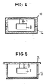
- FIGS. 4 and 5 show special forms of a hermetically sealed housing for the dielectric resonator, which also permit electrical coupling through the cylinder wall.
- the housing here is made of glass, whereby in the exemplary embodiment according to FIG. 4 two trough-shaped half-shells 13, 14 are arranged with their end faces lying one on top of the other and 5, the housing consists of a cup-shaped glass container 15 with an attached cover plate 7c.
- the dielectric resonator 8 is also attached to the top of the housing via the glass rod 9.
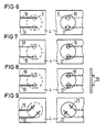
- FIGS. 6 to 9 show in partial representations different embodiments of the coupling of the dielectric resonator to the electrical circuit on the layer circuit board.
- the area of the layer circuit board 4 is shown in front and rear view that lies in the area of the cavity containing the dielectric resonator.
- the contour of the cavity is shown as a dashed circle (front) or closed circle (back).
- recesses 16, 17 are made on the entire surface of the metal-coated rear side. 4 extend over these recesses 16, 17 on the opposite, front side of the layer circuit board 4, which are then plated through to the metallized rear side of the layer circuit board 4 and lead to ground (FIG. 6).
- the plated-through end regions of the microstrip lines 18, 19 are designed as a coupling loop and, in the exemplary embodiment according to FIG. 8, as wire clips 20 projecting into the cavity 6.
- FIG. 9 shows a coupling of the dielectric resonator in the form of a slot coupling.
- the end regions of the microstrip lines 18, 19 are angled so that they are perpendicular to slot-shaped recesses 21, 22 extend on the opposite metallized rear side of the layer circuit board 4.
- a preferred embodiment is the coupling according to FIG. 7, because on the one hand a fixed coupling with the dielectric resonator is possible and on the other hand the coupling from one coupling point to the other is relatively low.
- the space between the layer circuit board 4 and the lower metal cover 3 can be divided into individual chambers, into which the individual sections of a multi-section layer circuit board may be inserted.
- the embodiments of the microwave oscillator according to the invention allow the setting of the electromagnetic coupling between the dielectric resonator and an electrical circuit by geometric changes in the coupling elements or by mechanical changes in the distance between the dielectric resonator and the circuit.
- the dielectric resonator is very effective and permanently protected from air humidity.
- the connection points (soldering areas and glue points) are easy to control. With such a configuration of the dielectric resonator, its mechanical assignment to the electrical circuit can take place during the final inspection, so that subsequent reliable cleaning of the dielectric resonator is possible.
Landscapes
- Inductance-Capacitance Distribution Constants And Capacitance-Resistance Oscillators (AREA)
- Constitution Of High-Frequency Heating (AREA)
- Surgical Instruments (AREA)
- Control Of Motors That Do Not Use Commutators (AREA)
Abstract
Description
- Die Erfindung bezieht sich auf einen Mikrowellenoszillator mit einem, mit einer elektrischen Schaltung elektromagnetisch gekoppelten dielektrischen Resonator.
- Aus der DE 29 31 428 C2 ist ein Mikrowellenoszillator mit einem Hohlraumresonator und mit einem mit dem Hohlraumresonator gekoppelten Festkörper-Bauelement bekannt. Das Festkörper-Bauelement ist dabei auf einer von dem topfförmigen Resonator überdeckten metallischen Grundplatte angeordnet und mit seinem Masseanschluß leitend auf einem in der Grundplatte befestigten Schraubfuß aufgebracht.
- Bei Oszillatoren mit einem dielektrischen Resonator sind die Eigenschaften von der Luftfeuchte abhängig, da Resonanzfrequenz und Güte dielektrischer Resonatoren u.a. Funktionen der sie umgebenden Luftfeuchte sind.
- Der Erfindung liegt die Aufgabe zugrunde, einen Oszillator mit einem dielektrischen Resonator zu schaffen, dessen Eigenschaften unabhängig von der Luftfeuchte sind und der eine Herstellung ermöglicht, bei der der dielektrische Resonator erst am Ende des Fertigungsablaufes dem Oszillator mechanisch fest zugeordnet wird.
- Diese Aufgabe wir gemäß der Erfindung in der Weise gelöst, daß der dielektrische Resonator in einem hermetisch dichten Hohlraum innerhalb eines die elektrische Schaltung aufnehmenden Metallgehäuses in entsprechender Lage zu Koppelelementen auf einer die elektrische Schaltung tragenden, einseitig ganzflächig metallisierten Schichtschaltungsplatte angeordnet ist. Vorteilhafte Ausgestaltungen und Weiterbildungen des Erfindungsgegenstandes sind in den Unteransprüchen angegeben.
- Nachstehend wird die Erfindung anhand von in der Zeichnung dargestellten Ausführungsbeispielen näher erläutert.
- Es zeigen
- Figur 1 einen Mikrowellenoszillator mit einem hermetisch dichten dielektrischen Resonator,
- Figuren 2 bis 5 in Teildarstellungen den Mikrowellenoszillator mit unterschiedlicher Ausbildung des hermetisch dichten dielektrischen Resonators und
- Figuren 6 bis 9 verschiedene Ausführungsformen der Ankopplung des dielektrischen Resonators an die elektrische Schaltung auf der Schichtschaltungsplatte.
- Fig. 1 zeigt einen Mikrowellenoszillator mit hermetisch dichtem dielektrischen Resonator im Querschnitt. Dabei ist ein beidseitig offenes Metallgehäuse 1 vorgesehen, das mit Metalldeckeln 2,3 abschließbar ist. Das Metallgehäuse 1 ist stufenförmig abgesetzt, so daß ein unterer Bereich größeren Querschnitts und ein oberer Bereich kleineren Querschnitts gebildet wird. In den unteren Bereich ist eine Schichtschaltungsplatte 4 eingesetzt, die an ihrer dem oberen Bereich des Metallgehäuses zugekehrten Rückseite ganzflächig metallisiert ist und auf der Vorderseite die Elemente der aktiven Oszillatorschaltung, beispielsweise den Transistor 5 sowie die Koppelorgane trägt, die durch Öffnungen in der rückseitigen Metallisierung der Schichtschaltungsplatte 4 die elektromagnetische Verkopplung mit einem im oberen Bereich des Metallgehäuses angeordneten dielektrischen Resonator 8 ermöglichen. Die Schichtschaltungsplatte 4 liegt mit ihrer metallisierten Rückseite auf Absätzen der Innenwand des Metallgehäuses an und ist mit diesem verlötet. Der dielektrische Resonator 8 befindet sich in einem beispielsweise zylindrischen Hohlraum 6, der seitlich von den Wänden des Metallgehäuses 1 umschlossen und hinsichtlich der Grundseiten einerseits von der Schichtschaltungsplatte 4 und andererseits von einer Quarzglasplatte 7 abgeschlossen ist, die im Abstand H zur Schichtschaltungsplatte 4 auf einem umflaufenden stufenförmigen Absatz der Innenwand des Metallgehäuses 1 aufliegt und mit diesem verklebt ist (Klebestelle 11). Somit wird durch die mit dem Metallgehäuse verlötete Schichtschaltungsplatte 4 und die mit dem Metallgehäuse verklebte Quarzglasplatte 7 ein hermetisch dichter Hohlraum für den dielektrischen Resonator 8 geschaffen. Der dielektrische Resonator 8 ist über einen Glasstift 9 mit der Schichtschaltungsplatte 4 verklebt. Ferner ist ein Element 10 zur Feinabstimmung vorgesehen, das aus einem im oberen Metalldeckel 2 geführten Gewindestift und einem an seiner Stirnseite angebrachten, z. B. metallischen Teller besteht. Dieser wird im Hohlraum zwischen Metalldeckel 2 und Quarzglasplatte 7 bewegt und beeinflußt damit die Resonanzfrequenz des dielektrischen Resonators 8.
- Fig. 2 zeigt in einer Teildarstellung einen Mikrowellenoszillator ähnlich dem nach Fig. 1. Unterschiedlich ist hierbei, daß der dielektrische Resonator 8 über den Glasstab 9 mit der Glasplatte 7 verklebt ist. Der Vorteil dieser Anordnung anstelle der Befestigung an der Schichtschaltungsplatte besteht darin, daß eine saubere Bearbeitung und Reinigung des dielektrischen Resonators zum Frequenzabgleich, eine Einstellung der Kopplung durch Änderung der Höhe H sowie eine gute Kontrolle der Klebestelle möglich sind.
- Fig. 3 zeigt in einer Teildarstellung eine Ausführungsform einer Halterung und Feuchtabdichtung für den dielektrischen Resonator, bei der der dielektrische Resonator in einem hermetisch dichten Gehäuse montiert ist, das aus einem in den oberen Bereich des Metallgehäuses 1 einsetzbaren metallischen Gewindering 12 und beiderseits auf dessen Öffnungen aufgesetzten Glasplatten 7a und 7b besteht. Der Vorteil dieser Anordnung besteht in einer einfachen Bearbeitung und Reinigung des dielektrischen Resonators vor dem Verschließen des Gehäuses, optimalen Prüfmöglichkeiten hinsichtlich der Dichtigkeit sowie einer einfachen Einstellung der elektrischen Kopplung und einfachen Reparaturmöglichkeit des Oszillators.
- Die Figuren 4 und 5 zeigen spezielle Formen eines hermetisch dichten Gehäuses für den dielektrischen Resonator, die auch eine elektrische Verkopplung durch die Zylinderwand gestatten. Unterschiedlich zu den bisher beschriebenen Ausführungsformen, die in der Regel für eine Kopplung durch den Boden des Gehäuses gedacht sind, besteht hierbei das Gehäuse jeweils aus Glas, wobei beim Ausführungsbeispiel nach Fig. 4 zwei wannenförmige Halbschalen 13,14 mit ihren Stirnseiten aufeinanderliegend angeordnet sind und beim Ausführungsbeispiel nach Fig. 5 das Gehäuse aus einem topfförmigen Glasbehälter 15 mit einer aufgesetzten Deckplatte 7c besteht. Der dielektrische Resonator 8 ist hierbei ebenfalls über den Glasstab 9 an der Oberseite des Gehäuses befestigt.
- Die Figuren 6 bis 9 zeigen in Teildarstellungen verschiedene Ausführungsformen der Ankopplung des dielektrischen Resonators an die elektrische Schaltung auf der Schichtschaltungsplatte. Dabei ist jeweils derjenige Bereich der Schichtschaltungsplatte 4 in Vorder- und Rückansicht dargestellt, der im Bereich des den dielektrischen Resonator enthaltenden Hohlraumes liegt. Die Kontur des Hohlraumes ist dabei als strichliert gezeichneter Kreis (Vorderseite) bzw. geschlossener Kreis (Rückseite) dargestellt. Im Bereich der Koppelorgane auf der Vorderseite der Schichtschaltungsplatte 4 sind auf deren ganzflächig metallisierter Rückseite Ausnehmungen 16,17 angebracht. Über diese Ausnehmungen 16,17 erstrecken sich auf der gegenüberliegenden, vorderen Seite der Schichtschaltungsplatte 4 Leiterbahnen 18,19, die dann zur metallisierten Rückseite der Schichtschaltungsplatte 4 durchkontaktiert und an Masse geführt sind (Fig. 6). Abweichend hiervon sind beim Ausführungsbeispiel nach Fig. 7 die durchkontaktierten Endbereiche der Mikrostripleitungen 18,19 als Koppelschleife und beim Ausführungsbeispiel nach Fig. 8 als in den Hohlraum 6 hineinragende Drahtbügel 20 ausgebildet.
- Fig. 9 zeigt eine Ankopplung des dielektrischen Resonators in Form einer Schlitzkopplung. Hierzu sind die Endbereiche der Mikrostripleitungen 18,19 so abgewinkelt, daß sie senkrecht zu schlitzförmigen Ausnehmungen 21,22 auf der gegenüberliegenden metallisierten Rückseite der Schichtschaltungsplatte 4 verlaufen.
- Eine bevorzugte Ausführungsform stellt dabei die Ankopplung nach Fig. 7 dar, weil einerseits eine feste Kopplung mit dem dielektrischen Resonator möglich ist und andererseits die Überkopplung von einer Koppelstelle zur anderen relativ gering ist. Um solche störend wirkenden Überkopplungen zwischen den einzelnen Koppelstellen ganz zu vermeiden, ist es vorteilhaft, zwischen den einzelnen Koppelstellen auf der Bauteileseite der Schichtschaltungsplatte 4 schirmende Trennwände einzufügen. Hierzu kann der Raum zwischen Schichtschaltungsplatte 4 und unterem Metalldekkel 3 in einzelne Kammern aufgeteilt werden, in die gegebenenfalls die einzelnen Abschnitte einer mehrfach unterteilten Schichtschaltungsplatte eingesetzt werden.
- Die erfindungsgemäßen Ausführungsformen des Mikrowellenoszillators gestatten das Einstellen der elektromagnetischen Kopplung zwischen dielektrischem Resonator und einer elektrischen Schaltung durch geometrische Änderungen der Koppelorgane oder durch mechanische Abstandsänderungen zwischen dielektrischem Resonator und Schaltung. Der dielektrische Resonator ist dabei sehr wirkungsvoll und beständig vor Luftfeuchte geschützt. Die Verbindungsstellen (Lötflächen und Klebestellen) sind gut kontrollierbar. Bei einer solchen Ausgestaltung des dielektrischen Resonators kann seine mechanische Zuordnung zur elektrischen Schaltung während der Endprüfung erfolgen, so daß eine anschließend notwendige zuverlässige Reinigung des dielektrischen Resonators möglich ist.
Claims (15)
dadurch gekennzeichnet, daß der dielektrische Resonator in einem hermetisch dichten Hohlraum innerhalb eines die elektrische Schaltung aufnehmenden Metallgehäuses in entsprechender Lage zu Koppelelementen auf einer die elektrische Schaltung tragenden, einseitig ganzflächig metallisierten Schichtschaltungsplatte angeordnet ist.
dadurch gekennzeichnet, daß die Glasplatte mit den Gehäuseseitenwänden verklebt ist.
dadurch gekennzeichnet, daß die Innenseiten des Metallgehäuses in einem der Höhe des Hohlraums entsprechenden Abstand derart stufenförmig abgesetzt sind, daß Schichtschaltungsplatte und Glasplatte auf den so gebildeten Absätzen aufliegen.
dadurch gekennzeichnet, daß der dielektrische Resonator innerhalb eines separaten hermetisch dichten Gehäuses angeordnet ist, das in das Metallgehäuse eingesetzt ist.
dadurch gekennzeichnet, daß das Gehäuse aus einem Gewindering und beidseitig aufgesetzten Glasplatten besteht.
dadurch gekennzeichnet, daß das Gehäuse aus zwei mit ihren Stirnseiten aufeinanderliegenden wannenförmigen Halbschalen aus Glas besteht.
dadurch gekennzeichnet, daß das Gehäuse aus einem topfförmigen Glasbehälter und einer aufgesetzten Deckplatte besteht.
dadurch gekennzeichnet, daß der dielektrische Resonator über einen Glasstift an einer der den Hohlraum abschließenden Grundflächen befestigt ist.
dadurch gekennzeichnet, daß ein Feinabstimmelement vorgesehen ist, das in eine Bohrung der metallischen Abdeckung des Metallgehäuses eingesetzt und zwischen der metallischen Abdeckung und der Abdeckung des den dielektrischen Resonator aufnehmenden Hohlraums angeordnet ist.
dadurch gekennzeichnet,1 daß das Metallgehäuse an seinen Stirnseiten offen und in seiner Höhe stufenförmig abgesetzt ist derart, daß der untere Bereich den Querschnitt der einzusetzenden Schichtschaltungsplatte und der obere, den Hohlraum für den dielektrischen Resonator bildende Bereich einen kleineren Querschnitt aufweist und beide Stirnseiten des Metallgehäuses mit Metalldeckeln abschließbar sind.
dadurch gekennzeichnet, daß die Ankopplung des dielektrischen Resonators an die elektrische Schaltung über durchkontaktierte Mikrostripleitungen erfolgt.
dadurch gekennzeichnet, daß die Ankopplung des dielektrischen Resonators an die elektrische Schaltung über eine durchkontaktierte Koppelschleife erfolgt.
dadurch gekennzeichnet, daß die Ankopplung des dielektrischen Resonators an die elektrische Schaltung über Drahtbügel erfolgt.
dadurch gekennzeichnet, daß die Ankopplung des dielektrischen Resonators an die elektrische Schaltung über eine Schlitzkopplung-Mikrostrip auf der Bauteileseite der Schichtschaltungsplatte erfolgt.
Applications Claiming Priority (2)
| Application Number | Priority Date | Filing Date | Title |
|---|---|---|---|
| DE3812669 | 1988-04-15 | ||
| DE3812669 | 1988-04-15 |
Publications (3)
| Publication Number | Publication Date |
|---|---|
| EP0337371A2 true EP0337371A2 (de) | 1989-10-18 |
| EP0337371A3 EP0337371A3 (en) | 1990-03-14 |
| EP0337371B1 EP0337371B1 (de) | 1994-06-22 |
Family
ID=6352104
Family Applications (1)
| Application Number | Title | Priority Date | Filing Date |
|---|---|---|---|
| EP89106357A Expired - Lifetime EP0337371B1 (de) | 1988-04-15 | 1989-04-11 | Mikrowellenoszillator |
Country Status (4)
| Country | Link |
|---|---|
| US (1) | US4922211A (de) |
| EP (1) | EP0337371B1 (de) |
| AT (1) | ATE107814T1 (de) |
| DE (1) | DE58907921D1 (de) |
Cited By (1)
| Publication number | Priority date | Publication date | Assignee | Title |
|---|---|---|---|---|
| EP0519308A3 (en) * | 1991-06-19 | 1993-08-04 | Siemens Telecomunicazioni S.P.A. | Resonating microwave cavity with double dielectric resonator and tunable resonance frequency |
Families Citing this family (16)
| Publication number | Priority date | Publication date | Assignee | Title |
|---|---|---|---|---|
| US5221913A (en) * | 1990-09-26 | 1993-06-22 | Matsushita Electric Industrial Co., Ltd. | Dielectric resonator device with thin plate type dielectric heat-radiator |
| JPH04294616A (ja) * | 1991-03-23 | 1992-10-19 | Fukushima Nippon Denki Kk | 電圧制御発振器 |
| US5140285A (en) * | 1991-08-26 | 1992-08-18 | Ail Systems, Inc. | Q enhanced dielectric resonator circuit |
| GB2268628B (en) * | 1992-07-07 | 1995-10-11 | Northern Telecom Ltd | Affixing dielectric resonator on p.c.b. |
| US5717400A (en) * | 1992-09-11 | 1998-02-10 | Honda Giken Kogyo Kabushiki Kaisha | High-frequency signal generator and radar module |
| US5394154A (en) * | 1992-09-11 | 1995-02-28 | Honda Giken Kogyo Kabushiki Kaisha | High-frequency signal generator and radar module |
| US5392051A (en) * | 1992-09-11 | 1995-02-21 | Honda Giken Kogyo Kabushiki Kaisha | High-frequency signal generator |
| US5428326A (en) * | 1993-12-29 | 1995-06-27 | The United States Of America As Represented By The Secretary Of The Army | Fast turn-on, temperature stable dielectric resonator oscillator |
| KR20020005813A (ko) * | 2000-07-10 | 2002-01-18 | 이형도 | 디알오의 기판 실장장치 |
| JP2002026655A (ja) * | 2000-07-11 | 2002-01-25 | Hitachi Ltd | 発振装置および送受信装置ならびにその製造方法 |
| US20040021535A1 (en) * | 2002-07-31 | 2004-02-05 | Kenneth Buer | Automated dielectric resonator placement and attachment method and apparatus |
| JP3923405B2 (ja) * | 2002-10-09 | 2007-05-30 | シャープ株式会社 | 低雑音コンバータ |
| AU2003290525A1 (en) * | 2002-11-07 | 2004-06-03 | Sophia Wireless, Inc. | Coupled resonator filters formed by micromachining |
| EP2183815A1 (de) * | 2007-08-31 | 2010-05-12 | BAE Systems PLC | Vibrationsarme dielektrische resonanzoszillatoren |
| EP2188864A1 (de) * | 2007-08-31 | 2010-05-26 | BAE Systems PLC | Vibrationsarme dielektrische resonanzoszillatoren |
| US8305165B2 (en) * | 2007-08-31 | 2012-11-06 | Bae Systems Plc | Dielectric resonant oscillator having printed circuit probes that conform to the curvature of a casing wall |
Family Cites Families (6)
| Publication number | Priority date | Publication date | Assignee | Title |
|---|---|---|---|---|
| DE2931428C2 (de) * | 1979-08-02 | 1982-03-04 | Siemens AG, 1000 Berlin und 8000 München | Mikrowellenoszillator |
| JPS6051009A (ja) * | 1983-08-30 | 1985-03-22 | Nec Corp | マイクロ波発振器 |
| US4628283A (en) * | 1983-11-07 | 1986-12-09 | The Narda Microwave Corporation | Hermetically sealed oscillator with dielectric resonator tuned through dielectric window by adjusting screw |
| JPS60137107A (ja) * | 1983-12-26 | 1985-07-20 | Toshiba Corp | マイクロ波固体発振器 |
| US4630004A (en) * | 1985-04-11 | 1986-12-16 | The United States Of America As Represented By The Secretary Of The Air Force | Dielectric resonator stabilized microstrip oscillator |
| US4733198A (en) * | 1986-10-06 | 1988-03-22 | Murata Erie North America, Inc. | Mechanically tunable sealed microwave oscillator |
-
1989
- 1989-03-06 US US07/318,969 patent/US4922211A/en not_active Expired - Fee Related
- 1989-04-11 AT AT89106357T patent/ATE107814T1/de not_active IP Right Cessation
- 1989-04-11 DE DE58907921T patent/DE58907921D1/de not_active Expired - Fee Related
- 1989-04-11 EP EP89106357A patent/EP0337371B1/de not_active Expired - Lifetime
Cited By (1)
| Publication number | Priority date | Publication date | Assignee | Title |
|---|---|---|---|---|
| EP0519308A3 (en) * | 1991-06-19 | 1993-08-04 | Siemens Telecomunicazioni S.P.A. | Resonating microwave cavity with double dielectric resonator and tunable resonance frequency |
Also Published As
| Publication number | Publication date |
|---|---|
| DE58907921D1 (de) | 1994-07-28 |
| US4922211A (en) | 1990-05-01 |
| ATE107814T1 (de) | 1994-07-15 |
| EP0337371A3 (en) | 1990-03-14 |
| EP0337371B1 (de) | 1994-06-22 |
Similar Documents
| Publication | Publication Date | Title |
|---|---|---|
| EP0337371B1 (de) | Mikrowellenoszillator | |
| DE69521956T2 (de) | Funkfrequenzfilter mit helikoidalen Resonatoren | |
| DE69431412T2 (de) | Dielektrischer Resonator, dielektrisches Bandsperrfilter und dielektrisches Filter | |
| DE2538614C3 (de) | Dielektrischer Resonator | |
| DE69033490T2 (de) | Keramischer Bandfilter | |
| DE69706009T2 (de) | Oszillator | |
| DE69218674T2 (de) | Temperaturkompensiertes dielektrisches Filter | |
| DE19520217C2 (de) | Piezoelektrische Resonanzkomponente des Chip-Typs | |
| DE10066293B4 (de) | Induktiver Sensor | |
| DE4030763C2 (de) | Dielektrisches Filter | |
| DE69032666T2 (de) | Eingekapselter piezoelektrischer Resonator | |
| DE19712065A1 (de) | Duplexer-Baueinheit | |
| DE3539504C2 (de) | ||
| CH679189A5 (de) | ||
| DE69422968T2 (de) | Montageanordnung für elektronisches Bauteil | |
| DE2755116C2 (de) | Oszillator mit einem in einem Gehäuse dicht eingebauten Resonator | |
| EP0154703B1 (de) | Resonator | |
| DE69323660T2 (de) | Koaxialer Resonator und dielektrisches Filter mit einem derartigen Resonator | |
| DE2312155C3 (de) | Verfahren zur Herstellung einer Aufhängung für einen Quarzstab | |
| DE10108927A1 (de) | Nicht-reziprokes Schaltungsbauelement und Hochfrequenzschaltungsvorrichtung | |
| DE4241027C2 (de) | Abstimmbarer dielektrischer Resonator | |
| DE10018682A1 (de) | Piezoelektrisches Bauelement und piezoelektrischer Oszillator, bei dem es Verwendung findet | |
| DE68920158T2 (de) | Filter mit verteilten Impedanzelementen. | |
| DE68903705T2 (de) | Kompakter filter mit resonatoren und mit verwendung des piezoelektrischen effektes. | |
| DE19824793A1 (de) | Piezoelekrisches Filter |
Legal Events
| Date | Code | Title | Description |
|---|---|---|---|
| PUAI | Public reference made under article 153(3) epc to a published international application that has entered the european phase |
Free format text: ORIGINAL CODE: 0009012 |
|
| AK | Designated contracting states |
Kind code of ref document: A2 Designated state(s): AT BE CH DE FR GB IT LI NL SE |
|
| PUAL | Search report despatched |
Free format text: ORIGINAL CODE: 0009013 |
|
| AK | Designated contracting states |
Kind code of ref document: A3 Designated state(s): AT BE CH DE FR GB IT LI NL SE |
|
| 17P | Request for examination filed |
Effective date: 19900726 |
|
| 17Q | First examination report despatched |
Effective date: 19921218 |
|
| GRAA | (expected) grant |
Free format text: ORIGINAL CODE: 0009210 |
|
| AK | Designated contracting states |
Kind code of ref document: B1 Designated state(s): AT BE CH DE FR GB IT LI NL SE |
|
| PG25 | Lapsed in a contracting state [announced via postgrant information from national office to epo] |
Ref country code: IT Free format text: LAPSE BECAUSE OF FAILURE TO SUBMIT A TRANSLATION OF THE DESCRIPTION OR TO PAY THE FEE WITHIN THE PRE;WARNING: LAPSES OF ITALIAN PATENTS WITH EFFECTIVE DATE BEFORE 2007 MAY HAVE OCCURRED AT ANY TIME BEFORE 2007. THE CORRECT EFFECTIVE DATE MAY BE DIFFERENT FROM THE ONE RECORDED.SCRIBED TIME-LIMIT Effective date: 19940622 Ref country code: BE Effective date: 19940622 Ref country code: FR Effective date: 19940622 Ref country code: NL Effective date: 19940622 Ref country code: GB Effective date: 19940622 |
|
| REF | Corresponds to: |
Ref document number: 107814 Country of ref document: AT Date of ref document: 19940715 Kind code of ref document: T |
|
| REF | Corresponds to: |
Ref document number: 58907921 Country of ref document: DE Date of ref document: 19940728 |
|
| PG25 | Lapsed in a contracting state [announced via postgrant information from national office to epo] |
Ref country code: SE Effective date: 19940922 |
|
| EN | Fr: translation not filed | ||
| NLV1 | Nl: lapsed or annulled due to failure to fulfill the requirements of art. 29p and 29m of the patents act | ||
| GBV | Gb: ep patent (uk) treated as always having been void in accordance with gb section 77(7)/1977 [no translation filed] |
Effective date: 19940622 |
|
| PG25 | Lapsed in a contracting state [announced via postgrant information from national office to epo] |
Ref country code: AT Effective date: 19950411 |
|
| PLBE | No opposition filed within time limit |
Free format text: ORIGINAL CODE: 0009261 |
|
| STAA | Information on the status of an ep patent application or granted ep patent |
Free format text: STATUS: NO OPPOSITION FILED WITHIN TIME LIMIT |
|
| PG25 | Lapsed in a contracting state [announced via postgrant information from national office to epo] |
Ref country code: LI Effective date: 19950430 Ref country code: CH Effective date: 19950430 |
|
| 26N | No opposition filed | ||
| REG | Reference to a national code |
Ref country code: CH Ref legal event code: PL |
|
| PGFP | Annual fee paid to national office [announced via postgrant information from national office to epo] |
Ref country code: DE Payment date: 19970617 Year of fee payment: 9 |
|
| PG25 | Lapsed in a contracting state [announced via postgrant information from national office to epo] |
Ref country code: DE Free format text: LAPSE BECAUSE OF NON-PAYMENT OF DUE FEES Effective date: 19990202 |