EP0337306B2 - Kraftfahrzeug-Schaumlöscheinheit - Google Patents
Kraftfahrzeug-Schaumlöscheinheit Download PDFInfo
- Publication number
- EP0337306B2 EP0337306B2 EP89106134A EP89106134A EP0337306B2 EP 0337306 B2 EP0337306 B2 EP 0337306B2 EP 89106134 A EP89106134 A EP 89106134A EP 89106134 A EP89106134 A EP 89106134A EP 0337306 B2 EP0337306 B2 EP 0337306B2
- Authority
- EP
- European Patent Office
- Prior art keywords
- foam
- pump
- extinguishing unit
- pressure
- water pump
- Prior art date
- Legal status (The legal status is an assumption and is not a legal conclusion. Google has not performed a legal analysis and makes no representation as to the accuracy of the status listed.)
- Expired - Lifetime
Links
- 239000006260 foam Substances 0.000 title claims description 62
- XLYOFNOQVPJJNP-UHFFFAOYSA-N water Substances O XLYOFNOQVPJJNP-UHFFFAOYSA-N 0.000 claims abstract description 33
- 150000001875 compounds Chemical class 0.000 claims description 13
- 230000002093 peripheral effect Effects 0.000 claims description 3
- 238000005259 measurement Methods 0.000 claims 1
- 239000004088 foaming agent Substances 0.000 abstract 1
- 239000003795 chemical substances by application Substances 0.000 description 23
- 238000010276 construction Methods 0.000 description 2
- 239000007921 spray Substances 0.000 description 2
- 230000007423 decrease Effects 0.000 description 1
- 230000001105 regulatory effect Effects 0.000 description 1
- 238000011144 upstream manufacturing Methods 0.000 description 1
Images
Classifications
-
- A—HUMAN NECESSITIES
- A62—LIFE-SAVING; FIRE-FIGHTING
- A62C—FIRE-FIGHTING
- A62C5/00—Making of fire-extinguishing materials immediately before use
- A62C5/02—Making of fire-extinguishing materials immediately before use of foam
-
- A—HUMAN NECESSITIES
- A62—LIFE-SAVING; FIRE-FIGHTING
- A62C—FIRE-FIGHTING
- A62C27/00—Fire-fighting land vehicles
Definitions
- the invention relates to a motor vehicle foam extinguishing unit with a water tank, a motor-driven water pump and a pressure outlet as a hose or pipe, and with a foam agent tank, a foam agent pump and a mixer for the pressure outlet.
- the object of the invention is to provide a motor vehicle foam extinguishing unit of the type mentioned, which not only avoids the additional control effort required by the foam agent pump according to the prior art, but is also very compact, can be manufactured at low cost and can be operated reliably.
- the subject of the invention is further developed by the features of subclaims 2 to 6.
- the essence of the invention is to arrange the water pump and foam pump on a single shaft or on a shaft train which is driven by the drive motor which is already provided in the motor vehicle.
- the foam agent pump is designed for a higher pump pressure than the water pump. In particular, it emits an approximately four bar higher pressure than the water pump. It is preferably equipped with a peripheral rotor.
- a known admixing regulator can be used as the admixer. Alternatively, however, the admixer has an electronic control device with corresponding sensors and control valves.
- the problem is therefore solved by driving the foam pump and the fire-fighting centrifugal pump in a tandem design by the vehicle engine.
- the foam compound pump can be accommodated anywhere in the drive shaft to the water pump or directly in a compact design on the water pump. If the machine operator regulates the delivery rate of the water pump up or down, the foam medium pressure also increases or decreases with the change in speed parallel to the water pressure.
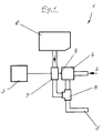
- a foam extinguishing unit (1) of a motor vehicle in particular a fire engine, comprises a water tank (2), a downstream water pump (4), the suction pipe connection of which is connected to the water tank (2).
- the pressure connection of the water pump (4) leads via a spray hose or a spray pipe (5) to the point of use, with an admixer (8) being interposed.
- the foam extinguishing unit (1) further comprises a foam agent pump (7), the suction connection of which is connected to a foam agent container (6) and the pressure connection of which is connected to the admixer (8) is to mix foam agent into the water in a suitable controlled manner so that a foam is formed which is ultimately sprayed to extinguish a fire or the like.
- the water pump (4) and foam compound pump (7) are driven by the same motor (3) that is the drive motor of the motor vehicle.
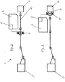
- Water pump (4) and foam agent pump (7) run according to the embodiment of FIG. 2 spaced apart on a shaft (10) or on a short shaft (9) according to FIG. 3 in a compact design.
- the shaft train (10) and shaft (9) are connected to the output side of the motor (3) via a cardan shaft.
- the foam agent container (6) is integrated with the water container (2).
- the position of the foam compound container (6) in the water container (2) is determined by the position of the foam compound pump (7) in the drive train.
- the position of the foam agent container (6) is selected so that there is a short foam agent piping to the suction side of the foam agent pump (7).
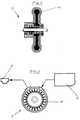
- the foam agent pump (7) is designed according to FIGS. 4 and 5 with a so-called peripheral rotor (11).
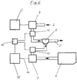
- FIG. 6 The basic sketch of a motor vehicle foam extinguishing unit according to the prior art is shown in FIG. 6.
- the foam extinguishing unit (1) according to the invention according to FIG. 1 in the prior art there is an additional pressure meter (12) on the pressure side of the water pump upstream of the admixer (8) and another pressure meter (13) on the pressure side of the foam agent pump (7) .
- Both pressures are compared in the controller (14) and the pressure of the pressure gauge (13) is adjusted by a motor (15) which separately drives the foam agent pump (7) in such a way that the foam agent pressure delivered is greater than the water pump pressure.
- the units (12, 13, 14, 15) and drive shaft (16) between the motor (15) and foam pump (7) which are provided according to the prior art, are omitted in the invention.
Landscapes
- Health & Medical Sciences (AREA)
- Public Health (AREA)
- Business, Economics & Management (AREA)
- Emergency Management (AREA)
- Structures Of Non-Positive Displacement Pumps (AREA)
- Fire-Extinguishing By Fire Departments, And Fire-Extinguishing Equipment And Control Thereof (AREA)
- Exhaust Gas After Treatment (AREA)
Description
- Die Erfindung betrifft eine Kraftfahrzeug-Schaumlöscheinheit mit Wasserbehälter, kraftfahrzeugmotorgetriebener Wasserpumpe und Druckausgang als Schlauch oder Rohr, sowie mit einem Schaummittelbehälter, einer Schaummittelpumpe und einem Zumischer zum Druckausgang.
- Bei der Druckzumischung an Feuerwehrfahrzeugen ist es allgemein üblich, vom Fahrzeugmotor her die Feuerlöschkreiselpumpe anzutreiben und die Schaummittelpumpe mit einem Motor als Aggregat im Fahrzeug mitzuführen. Dieses Schaummittel-Pumpenaggregat muß sehr aufwendig geregelt werden, weil in jedem Betriebszustand ein bestimmter Schaummitteldruck dem Wasserdruck aufgegeben werden muß. Von Nachteil ist hier der höhere Regelaufwand sowie der höhere Raumbedarf für das Schaummittel-Pumpenaggregat.
- Aufgabe der Erfindung ist die Schaffung einer Kraftfahrzeug-Schaumlöscheinheit der eingangs genannten Art, die nicht nur den durch die Schaummittelpumpe nach dem Stand der Technik zusätzlichen Regelaufwand vermeidet, sondern sehr kompakt aufgebaut ist, zu niedrigen Kosten gefertigt und zuverlässig betrieben werden kann.
- Gelöst wird die der Erfindung zugrundeliegende Aufgabe durch die im kennzeichnenden Teil des Anspruchs 1 angegebenen Mittel.
- Vorteilhaft weitergebildet wird der Erfindungsgegenstand durch die Merkmale der Unteransprüche 2 bis 6. Wesen der Erfindung ist, Wasserpumpe und Schaummittelpumpe aufeiner einzigen Welle oder auf einem Wellenstrang anzuordnen, die bzw. der vom ohnehin beim Kraftfahrzeug vorgesehenen Antriebsmotor angetrieben ist. Die Schaummittelpumpe ist hierbei für einen höheren Pumpendruck ausgelegt als die Wasserpumpe. Insbesondere gibt sie einen ca. vier bar höheren Druck ab als die Wasserpumpe. Sie ist vorzugsweise mit einem Peripheralläufer ausgetattet. Als Zumischer kann ein an sich bekannter Zumischregler verwendet werden. Alternativ jedoch besitzt der Zumischer eine elektronische Regeleinrichtung mit entsprechenden Meßwertgebern und Regelventilen.
- Man erreicht dadurch eine sehr kompakte Bauweise mit niedrigen Kosten und vermeidet den Regelaufwand der Schaummittelpumpe. Die Verohrung kann relativ einfach erfolgen. Eine erfindungsgemäße Zumischung ersetzt sogar bisher bekannte Vormischeinrichtungen.
- Gemäß der Erfindung wird also das Problem gelöst, indem man die Schaummittelpumpe und die Feuerlöschkreiselpumpe in einer Tandem-Bauweise durch den Fahrzeugmotor antreibt. Dabei kann die Schaummittelpumpe irgendwo im Gelenkwellenstrang zur Wasserpumpe untergebracht werden oder direkt in kompaktbauweise an der Wasserpumpe. Wenn vom Maschinisten die Förderleistung der Wasserpumpe herauf- oder heruntergeregelt wird, geht in jedem Fall mit der Drehzahländerung parallel zum Wasserdruck auch der Schaummitteldruck herauf oder herunter.
- Aus DE-PS 1 023 675 ist es bekannt, Wasserpumpe und Schaummittelpumpe über ein Untersetzungsgetriebe anzutreiben. Ein derartiger Antrieb ist vergleichsweise aufwendig und inkompakt. Änlich aufwendig und inkompakt ist die Anordnung gemäß US-PS 3 115 158. Wasserpumpe und Schaummittelpumpe sind dort auf zwei unterschiedlichen Antriebsachsen vorgesehen. Von einer Tandembauweise wie bei der Erfindung kann nicht die Rede sein.
Ähnliches gilt für die Vorrichtung nach US-PS 4 448 256. Wenn auch die dortige Schaummittelpumpe für einen höheren Pumpendruck ausgelegt ist als die Wasserpumpe (wie das bei einer vorteilhaften Weiterbildung der Erfindung der Fall ist), so sind doch beide bekannten Pumpen nicht in einer Tandembauweise ausgeführt. - Die Erfindung wird nachfolgend anhand von Ausführungsbeispielen unter Bezugnahme auf die beigefügte Zeichnung vergleichsweise zum Stand der Technik näher beschrieben; es zeigen:
- Fig. 1 das grundsätzliche Anordnungsprinzip einer erfindungsgemäßen Kraftfahrzeug-Schaumlöscheinheit,
- Fig. 2 eine Schaumlöscheinheit nach Fig.1 mit Anordnung der Wasserpumpe und Schaummittelpumpe auf einem Wellenstrang,
- Fig. 3 eine schaumlöscheinheit nach Fig.1 mit Anordnung der Wasserpumpe und Schaummittelpumpe in Kompaktbauweise,
- Fig. 4 eine Schaummittelpumpe in einem schematischen Axialschnitt,
- Fig. 5 die Schaummittelpumpe nach Fig. 4 in einem Querschnitt mit den Anschlußaggregaten, und
- Fig. 6 eine der Fig. 1 entsprechende Anordnung einer bekannten Kraftfahrzeug-Schaumlöscheinheit.
- Nach den Fig. 1 bis 5 umfaßt eine Schaumlöscheinheit (1) eines Kraftfahrzeugs, insbesondere Feuerwehrfahrzeugs, einen Wasserbehälter (2), eine nachgeordnete Wasserpumpe (4), dessen Saugrohranschluß mit dem Wasserbehälter (2) verbunden ist. Der Druckanschluß der Wasserpumpe (4) führt über einen Spritzschlauch oder ein Spritzrohr (5) zur Verwendungsstelle, wobei ein Zumischer (8) zwischengeordnet ist.
- Ferner umfaßt die Schaumlöscheinheit (1) eine Schaummittelpumpe (7), deren Sauganschluß mit einem Schaummittelbehälter (6) in Verbindung steht und deren Druckanschluß an den Zumischer (8) angeschlossen ist, um Schaummittel dem Wasser in geeigneter geregelter Weise zuzumischen, so daß ein Schaum entsteht, welcher letztlich verspritzt wird, um einen Brand oder dergl. zu löschen.
- Wasserpumpe (4) und Schaummittelpumpe (7) werden im Betrieb vom gleichen Motor (3) angetrieben, der der Antriebsmotor des Kraftfahrzeugs ist. Wasserpumpe (4) und Schaummittelpumpe (7) laufen hierbei gemäß Ausführungsbeispiel nach Fig. 2 voneinander beabstandet auf einem Wellenstrang (10) oder auf einer kurzen Welle (9) gemäß Fig. 3 in einer Kompaktbauweise. Wellenstrang (10) und Welle (9) sind über eine Kardanwelle mit der Abtriebsseite des Motors (3) verbunden.
- Der Schaummittelbehälter (6) ist integriert mit dem Wasserbehälter (2) ausgebildet. Die Lage des Schaummittelbehälters (6) im Wasserbehälter (2) wird bestimmt durch die Lage der Schaummittelpumpe (7) im Antriebsstrang. Insbesondere ist die Lage des Schaummittelbehälters (6) so gewählt, daß sich eine kurze Schaummittelverrohrung zur Saugseite der Schaummittelpumpe (7) ergibt.
- Die Schaummittelpumpe (7) ist gemäß den Fig. 4 und 5 mit einem sog. Peripheralläufer (11) ausgebildet.
- Die Prinzipskizze einer Kraftfahrzeug-Schaumlöscheinheit nach dem Stand der Technik ist in Fig. 6 gezeigt. Im Vergleich zur erfindungsgemäßen Schaumlöscheinheit (1) nach Fig. 1 ergibt sich beim Stand der Technik ein zusätzlicher Druckmesser (12) auf der Druckseite der Wasserpumpe vor dem Zumischer (8) sowie ein weiterer Druckmesser (13) auf der Druckseite der Schaummittelpumpe (7). Beide Drücke werden im Regler (14) verglichen und der Druck des Druckmessers (13) über einen die Schaummittelpumpe (7) separat antreibenden Motor (15) in einer Weise nachgeregelt, daß der abgegebene Schaummitteldruck größer ist als der Wasserpumpendruck. Ersichtlich entfallen bei der Erfindung die nach dem Stand der Technik vorgesehenen Aggregate (12, 13, 14, 15) sowie Antriebswelle (16) zwischen Motor (15) und Schaummittelpumpe (7).
Claims (6)
- Kraftfahrzeug-Schaumlöscheinheit (1) mit Wasserbehälter (2), kraftfahrzeugmotorgetriebener Wasserpumpe (4) und Druckausgang als Schlauch oder Rohr (5), sowie mit einem Schaummittelbehälter (6), einer Schaummittelpumpe (7) und einem Zumischer (8) zum Druckausgang (5),
dadurch gekennzeichnet,
daß Wasserpumpe (4) und Schaummittelpumpe (7) hintereinander entweder dicht zueinander auf einer einzigen kraftfahrzeugmotorgetriebenen Welle (9) oder voneinander beabstandet auf einem einzigen kraftfahrzeugmotorgetriebenen Wellenstrang (10) angeordnet sind, wobei der Schaummittelbehälter (6) im Wasserbehälter (2) integriert angeordnet und im Bereich der Schaummittelpumpe (7) gelegen ist. - Schaumlöscheinheit nach Anspruch 1,
dadurch gekennzeichnet,
daß die Schaummittelpumpe (7) für einen höheren Pumpendruck ausgelegt ist als die Wasserpumpe (4). - Schaumlöscheinheit nach Anspruch 2,
dadurch gekennzeichnet,
daß die Schaummittelpumpe (7) einen ca. vier bar höheren Druck als die Wasserpumpe (4) abgibt. - Schaumlöscheinheit nach einem der Ansprüche 1 bis 3,
dadurch gekennzeichnet,
daß die Schaummittelpumpe (7) einen Peripheralläufer (11) aufweist. - Schaumlöscheinheit nach einem der Ansprüche 1 bis 4,
dadurch gekennzeichnet,
daß der Zumischer (8) ein an sich bekannter Zumischregler ist. - Schaumlöscheinheit nach einem der Ansprüche 1 bis 4,
dadurch gekennzeichnet,
daß der Zumischer (8) eine elektronische Regeleinrichtung mit entsprechenden Meßwertgebern und Regelventilen aufweist.
Priority Applications (1)
| Application Number | Priority Date | Filing Date | Title |
|---|---|---|---|
| AT89106134T ATE75153T1 (de) | 1988-04-15 | 1989-04-07 | Kraftfahrzeug-schaumloescheinheit. |
Applications Claiming Priority (2)
| Application Number | Priority Date | Filing Date | Title |
|---|---|---|---|
| DE3812535A DE3812535A1 (de) | 1988-04-15 | 1988-04-15 | Kraftfahrzeug-schaumloescheinheit |
| DE3812535 | 1988-04-15 |
Publications (3)
| Publication Number | Publication Date |
|---|---|
| EP0337306A1 EP0337306A1 (de) | 1989-10-18 |
| EP0337306B1 EP0337306B1 (de) | 1992-04-22 |
| EP0337306B2 true EP0337306B2 (de) | 1997-10-08 |
Family
ID=6352041
Family Applications (1)
| Application Number | Title | Priority Date | Filing Date |
|---|---|---|---|
| EP89106134A Expired - Lifetime EP0337306B2 (de) | 1988-04-15 | 1989-04-07 | Kraftfahrzeug-Schaumlöscheinheit |
Country Status (3)
| Country | Link |
|---|---|
| EP (1) | EP0337306B2 (de) |
| AT (1) | ATE75153T1 (de) |
| DE (2) | DE3812535A1 (de) |
Families Citing this family (1)
| Publication number | Priority date | Publication date | Assignee | Title |
|---|---|---|---|---|
| EP1726333A1 (de) * | 2005-05-25 | 2006-11-29 | Unisantis Europe GmbH | Flüssigkeitsfördereinrichtung für Feuerwehrvorrichtung |
Family Cites Families (6)
| Publication number | Priority date | Publication date | Assignee | Title |
|---|---|---|---|---|
| US3115158A (en) * | 1962-03-01 | 1963-12-24 | Sterling Prec Corp | Airfoam liquid proportioning system |
| DE2556245C2 (de) * | 1975-12-13 | 1985-08-08 | Albach & Co, 6230 Frankfurt | Zumischvorrichtung für ein Schaumlöschgerät |
| US4157733A (en) * | 1977-08-01 | 1979-06-12 | Emergency One, Inc. | Dual pump system for fire fighting vehicles |
| US4337830A (en) * | 1978-05-03 | 1982-07-06 | Hale Fire Pump Company | Pump assembly |
| DE3038334A1 (de) * | 1980-10-10 | 1982-10-21 | Albert Ziegler Gmbh & Co Kg, 7928 Giengen | Einrichtung fuer feuerloeschfahrzeuge zum zumischen eines schaum- oder filmbildenden zusatzmittels zum loeschwasserstroms |
| US4448256A (en) * | 1982-01-28 | 1984-05-15 | Hale Fire Pump Company | Foam liquid proportioner |
-
1988
- 1988-04-15 DE DE3812535A patent/DE3812535A1/de not_active Withdrawn
-
1989
- 1989-04-07 EP EP89106134A patent/EP0337306B2/de not_active Expired - Lifetime
- 1989-04-07 AT AT89106134T patent/ATE75153T1/de not_active IP Right Cessation
- 1989-04-07 DE DE8989106134T patent/DE58901218D1/de not_active Expired - Lifetime
Also Published As
| Publication number | Publication date |
|---|---|
| ATE75153T1 (de) | 1992-05-15 |
| DE3812535A1 (de) | 1989-10-26 |
| EP0337306B1 (de) | 1992-04-22 |
| EP0337306A1 (de) | 1989-10-18 |
| DE58901218D1 (de) | 1992-05-27 |
Similar Documents
| Publication | Publication Date | Title |
|---|---|---|
| DE2519152C2 (de) | Vorrichtung zum Anlassen von Flugzeugtriebwerken und zum Betreiben von Flugzeughilfsgeräten | |
| DE2736153B2 (de) | Filter- und Mischeinrichtung zur Vermischung von Schmieröl und Kraftstoff | |
| EP0786058B1 (de) | Automatgetriebe, insbesondere für kraftfahrzeuge | |
| DE3214688A1 (de) | Fluegelradpumpe | |
| DE2024125A1 (de) | Kombiniertes Hilfskraft und Trieb werkandrehsystem | |
| CH651794A5 (de) | Wasserstrahl-antriebsvorrichtung zum antrieb von wasserfahrzeugen. | |
| DE4216703B4 (de) | Getriebeanordnung für ein Fahrzeug | |
| EP0337306B2 (de) | Kraftfahrzeug-Schaumlöscheinheit | |
| DE2649558A1 (de) | Antriebseinheit mit mehreren gekoppelten druckluftmotoren | |
| DE3310663C2 (de) | Hochdruckreinigungsgerät | |
| DE2048904C3 (de) | Vorrichtung zum Einfuhren eines Zugabemittels in die Wasserhauptleitung einer Feuerloschanlage | |
| DE3131522C2 (de) | ||
| DE3240179A1 (de) | Stroemungsmittelkupplung | |
| EP0638333B1 (de) | Autom. mechanisch- u. elektronisch gesteuertes löschpumpendruckseitiges Schaumzumischsystem mit Schaummittelpumpe u. Notbetätigung | |
| DE102006030575A1 (de) | Vorrichtung zur Verwendung beim Verschwenken lenkbarer Fahrzeugräder | |
| EP3101179B1 (de) | Arbeitsgerät, insbesondere für eine baumaschine | |
| DE2911469A1 (de) | Antriebsanordnung, insbesondere fuer spritzgiessmaschinen | |
| DE102008007736A1 (de) | Hydraulisches Lenksystem | |
| CH681035A5 (de) | ||
| EP0012450A1 (de) | Vorrichtung zur Sicherung eines Kraftstoffeinspritz-Verbrennungsmotors vor einem Überdrehen | |
| DE102005057200B4 (de) | Feuerwehrfahrzeug | |
| DE102011007014A1 (de) | Vorrichtung zur Gabe eines haptisch erfahrbaren Signals auf eine Lenkwelle eines Fahrzeugs | |
| DE1299167C2 (de) | Regler fuer aus einer Brennkraftmaschine und einem hydrostatischen Getriebe bestehende Antriebseinrichtungen von Kraftfahrzeugen | |
| DE2950579C2 (de) | Verteilergehäuse für eine Flüssigkeitspumpe | |
| DE811891C (de) | Anordnung zur Drehzahlregelung von Brennkraftturbinen-Anlagen |
Legal Events
| Date | Code | Title | Description |
|---|---|---|---|
| PUAI | Public reference made under article 153(3) epc to a published international application that has entered the european phase |
Free format text: ORIGINAL CODE: 0009012 |
|
| AK | Designated contracting states |
Kind code of ref document: A1 Designated state(s): AT CH DE FR GB IT LI |
|
| 17P | Request for examination filed |
Effective date: 19900319 |
|
| 17Q | First examination report despatched |
Effective date: 19911008 |
|
| GRAA | (expected) grant |
Free format text: ORIGINAL CODE: 0009210 |
|
| AK | Designated contracting states |
Kind code of ref document: B1 Designated state(s): AT CH DE FR GB IT LI |
|
| REF | Corresponds to: |
Ref document number: 75153 Country of ref document: AT Date of ref document: 19920515 Kind code of ref document: T |
|
| ITF | It: translation for a ep patent filed | ||
| REF | Corresponds to: |
Ref document number: 58901218 Country of ref document: DE Date of ref document: 19920527 |
|
| ET | Fr: translation filed | ||
| GBT | Gb: translation of ep patent filed (gb section 77(6)(a)/1977) | ||
| PLBI | Opposition filed |
Free format text: ORIGINAL CODE: 0009260 |
|
| 26 | Opposition filed |
Opponent name: ALBERT ZIEGLER GMBH Effective date: 19930107 |
|
| PLAW | Interlocutory decision in opposition |
Free format text: ORIGINAL CODE: EPIDOS IDOP |
|
| PLAW | Interlocutory decision in opposition |
Free format text: ORIGINAL CODE: EPIDOS IDOP |
|
| PUAH | Patent maintained in amended form |
Free format text: ORIGINAL CODE: 0009272 |
|
| STAA | Information on the status of an ep patent application or granted ep patent |
Free format text: STATUS: PATENT MAINTAINED AS AMENDED |
|
| 27A | Patent maintained in amended form |
Effective date: 19971008 |
|
| AK | Designated contracting states |
Kind code of ref document: B2 Designated state(s): AT CH DE FR GB IT LI |
|
| REG | Reference to a national code |
Ref country code: CH Ref legal event code: AEN Free format text: AUFRECHTERHALTUNG DES PATENTES IN GEAENDERTER FORM |
|
| ITF | It: translation for a ep patent filed | ||
| GBTA | Gb: translation of amended ep patent filed (gb section 77(6)(b)/1977) |
Effective date: 19971231 |
|
| ET3 | Fr: translation filed ** decision concerning opposition | ||
| REG | Reference to a national code |
Ref country code: GB Ref legal event code: IF02 |
|
| PGFP | Annual fee paid to national office [announced via postgrant information from national office to epo] |
Ref country code: CH Payment date: 20040407 Year of fee payment: 16 |
|
| PGFP | Annual fee paid to national office [announced via postgrant information from national office to epo] |
Ref country code: FR Payment date: 20040421 Year of fee payment: 16 |
|
| PGFP | Annual fee paid to national office [announced via postgrant information from national office to epo] |
Ref country code: AT Payment date: 20040426 Year of fee payment: 16 |
|
| PGFP | Annual fee paid to national office [announced via postgrant information from national office to epo] |
Ref country code: GB Payment date: 20040429 Year of fee payment: 16 |
|
| PGFP | Annual fee paid to national office [announced via postgrant information from national office to epo] |
Ref country code: DE Payment date: 20040527 Year of fee payment: 16 |
|
| PG25 | Lapsed in a contracting state [announced via postgrant information from national office to epo] |
Ref country code: IT Free format text: LAPSE BECAUSE OF NON-PAYMENT OF DUE FEES;WARNING: LAPSES OF ITALIAN PATENTS WITH EFFECTIVE DATE BEFORE 2007 MAY HAVE OCCURRED AT ANY TIME BEFORE 2007. THE CORRECT EFFECTIVE DATE MAY BE DIFFERENT FROM THE ONE RECORDED. Effective date: 20050407 Ref country code: GB Free format text: LAPSE BECAUSE OF NON-PAYMENT OF DUE FEES Effective date: 20050407 Ref country code: AT Free format text: LAPSE BECAUSE OF NON-PAYMENT OF DUE FEES Effective date: 20050407 |
|
| PG25 | Lapsed in a contracting state [announced via postgrant information from national office to epo] |
Ref country code: LI Free format text: LAPSE BECAUSE OF NON-PAYMENT OF DUE FEES Effective date: 20050430 Ref country code: CH Free format text: LAPSE BECAUSE OF NON-PAYMENT OF DUE FEES Effective date: 20050430 |
|
| PG25 | Lapsed in a contracting state [announced via postgrant information from national office to epo] |
Ref country code: DE Free format text: LAPSE BECAUSE OF NON-PAYMENT OF DUE FEES Effective date: 20051101 |
|
| REG | Reference to a national code |
Ref country code: CH Ref legal event code: PL |
|
| GBPC | Gb: european patent ceased through non-payment of renewal fee |
Effective date: 20050407 |
|
| PG25 | Lapsed in a contracting state [announced via postgrant information from national office to epo] |
Ref country code: FR Free format text: LAPSE BECAUSE OF NON-PAYMENT OF DUE FEES Effective date: 20051230 |
|
| REG | Reference to a national code |
Ref country code: FR Ref legal event code: ST Effective date: 20051230 |