EP0336834A1 - Helmet breathing mask attachment device - Google Patents
Helmet breathing mask attachment device Download PDFInfo
- Publication number
- EP0336834A1 EP0336834A1 EP89400921A EP89400921A EP0336834A1 EP 0336834 A1 EP0336834 A1 EP 0336834A1 EP 89400921 A EP89400921 A EP 89400921A EP 89400921 A EP89400921 A EP 89400921A EP 0336834 A1 EP0336834 A1 EP 0336834A1
- Authority
- EP
- European Patent Office
- Prior art keywords
- mask
- helmet
- link
- shell
- rigid
- Prior art date
- Legal status (The legal status is an assumption and is not a legal conclusion. Google has not performed a legal analysis and makes no representation as to the accuracy of the status listed.)
- Granted
Links
Images

Classifications
-
- A—HUMAN NECESSITIES
- A62—LIFE-SAVING; FIRE-FIGHTING
- A62B—DEVICES, APPARATUS OR METHODS FOR LIFE-SAVING
- A62B18/00—Breathing masks or helmets, e.g. affording protection against chemical agents or for use at high altitudes or incorporating a pump or compressor for reducing the inhalation effort
- A62B18/08—Component parts for gas-masks or gas-helmets, e.g. windows, straps, speech transmitters, signal-devices
- A62B18/084—Means for fastening gas-masks to heads or helmets
Definitions
- the present invention relates to devices for fixing the shell of an auro-nasal breathing mask to a helmet, of the type comprising two fasteners each placed on one side of the vertical median plane of the mask and at least one of which is provided with '' a connecting member with quick coupling and unhooking.
- the fasteners comprise a continuous strap passing over the shell of the mask face cover at a relatively high level.
- the shell of the mask is provided so as to fit the chin and a second strap for connecting to the helmet passes under the mask so as to retain the latter, in particular in the event of ejection.
- the present invention aims to provide a mask fixing device that better meets those previously known to the requirements of practice, in particular in that it guarantees better holding of the mask on the face, in particular in the event of high respiratory overpressure or brutal acceleration and better sealing.
- each fastener is constituted by a rigid rod in the vertical direction and not extensible, allowing a relative movement of rotation of the mask relative to the helmet around d 'A direction perpendicular to the direction of the link and substantially parallel to the plane of symmetry of the face.
- an additional degree of adjustment or freedom will be provided, at least when the helmet and mask are not personalized, that is to say intended to be worn by one nobody.
- a simple solution which can also be adopted even in the case of personalized equipment, consists in fixing the link to the shell by means allowing the mask to rotate around an additional axis, substantially orthogonal to the shell.
- means for vertical adjustment of the point of attachment to the helmet will generally be provided.
- the mask can be allowed to rotate around an axis perpendicular to the direction of the link in various ways.
- the rod is constituted by a flexible blade resiliently, so as to be able to flex transversely.
- the link is rigid, but articulated at its ends around two axes which are substantially parallel to each other and parallel to the plane of symmetry of the face.
- connection member with quick coupling and removal
- connection member for each of the rods and, moreover, to constitute this member so that it allows easy adjustment of the mechanical pressure for applying the mask against the face.
- connection member of the type described in document US-A-4,577,375.
- the adjustment adjustment of the device to a particular carrier can be done by mounting the receptacle of the body on the helmet not rigidly, but on a vertical slide.
- connection member whatever the helmet on which the mask is mounted, it may be advantageous to provide the device so that the links are replaceable, various lengths of links can then be provided. Another solution is to provide rods of adjustable length.
- the arrangement according to the invention brings many advantages: the risk of the mask coming down under strong acceleration is eliminated, due to the rigidity of the rods which then work in bending in their direction of great rigidity.
- the tightness of the mask is retained even in the event of high respiratory overpressure, because the links are inextensible.
- the fitting of the mask is facilitated by the rigidity of the fasteners which means that the mask will always be placed in the same way when the connecting member or members are used.
- the visual field is increased: in fact the rods will generally be connected to the shell much lower than the usual straps, which less impairs vision and also makes it possible to lower a possible visor lower.
- the mask and the helmet constitute a rigid assembly once fixed to each other, the mask participates in the retention of the helmet in an immutable position relative to the head (the support of the mask against the nose bridge retaining the helmet in the event of head rotation) and increases the accuracy of a possible helmet sight.
- the device shown schematically in Figure 1 is intended to fix the shell 10 of a respiratory mask on the rigid shell 12 of an aviator helmet.
- the helmet shown has a conventional constitution: it includes, inside the shell 12 provided with padding 14, a cap 16 intended to be applied to the skull of the wearer.
- a visor 18 is movable, by controlled tilting using handles 20, between a high position where it is shown at 18 in FIG. 1 and a low position where it comes to bear against the shell 10.
- the fixing device comprises two fasteners arranged symmetrically relative to the vertical median plane of the mask shell.
- each fastener comprises a rigid rod 22 in flexion in a vertical plane, not extensible, articulated on the shell 10 of the mask and on the helmet around two axes 24 and 26 substantially parallel to the median plane and perpendicular to the length of the link. These two axes may not be exactly parallel when the link is twisted to take account of the flared shape of the shell of the face cover.
- One end of the link is therefore connected by a pin 24 to a connector 28.
- this connector 28 is mounted on the shell 10, for example by a rivet, so as to be able to rotate around a axis 30 perpendicular to axis 24 and directed towards the median plane.
- the other end of the link is articulated around the axis 26 on a component of a connection member 32 for quick insertion and removal.
- the member 32 may in particular be of the type described in document US-A-4 575 375.
- This member then comprises a receptacle 34 rigidly fixed to the shell 12 of the helmet and an assembly insertable into the receptacle.
- the rod is articulated around the axis 26 on a bayonet 36 belonging, with a control blade 38, to the assembly.
- the bayonet 36 has a double rack intended to be able to be inserted into the receptacle 34 by a simple push and allow adjustment step by step. It can only be removed by pulling on a flange 40 of the control blade 38.
- the rods are connected to the shell 10 of the mask at a level which is practically that of the pressure forces which tend to lift the mask in the event of overpressure inside. Consequently, it will in some cases be unnecessary to provide a strap connecting the bottom of the shell to the helmet. It will also be possible in some to use a shell that stops above the chin instead of nesting it.
- the link 22 shown in Figure 1 is in the form of a plate, hollowed out in the form of a double fork for the purpose of lightening. This constitution is not the only one possible and others will now be described by way of additional examples.
- FIG. 2 (where the members corresponding to those of FIG. 1 are designated by the same reference number) also comprises a mask shell 10, connected to the caterpillar 42 for supplying respiratory mixture and provided with 'a chin strap 44.
- the link 22a is constituted by a rectangular ring.
- the rapid insertion and removal connection member also comprises an insertable assembly articulated on the link 22a around the axis 26 and a receptacle 34 fixed to the helmet shell by two screws 46.
- the receptacle 34 instead of being fixed directly to the shell 12, is mounted on a vertical slide 48.
- Two screws 46 carried by the receptacle pass through ovalized holes of the slide and engage in threaded holes of a clamping plate, thus making it possible to adjust the vertical position of the receptacle according to the morphology of the individual who must wear the helmet and the mask.
- the bayonet 36 is provided with a loop 50 for receiving a strap 52 intended to hold in place a chin strap 44, the mask stopping this time above the chin.
- the mask covers only the mouth and the nose and the strap 52 is connected to a separate chin rest secured to the helmet and preventing it from lifting in the event of downward vertical acceleration.
- FIG. 5 shows a connecting rod 22b constituted by a flexible blade, generally metallic, intended to be fixed to the mask by a rivet or a screw leaving it free to rotate around the axis 30 and to be fixed rigidly or by the intermediate an axis with the bayonet 36.
- a connecting rod 22b constituted by a flexible blade, generally metallic, intended to be fixed to the mask by a rivet or a screw leaving it free to rotate around the axis 30 and to be fixed rigidly or by the intermediate an axis with the bayonet 36.
- the role of the two axes 24 and 26 of the previous embodiments is fulfilled by the lateral flexibility of the blade 22b, which must also remain rigid in the vertical direction.
- the link 22c is of adjustable length.
- it comprises a female part 54 pierced with a tapped hole into which a threaded rod 56 is screwed, provided on the other part.
- This arrangement is particularly advantageous when the mask has to adapt to helmets of various sizes: by giving the link the appropriate length, the adjustment bayonet can be inserted halfway under normal conditions of use thus leaving a significant adjustment latitude.
- the link can consist of two sliding blades one on top of the other and which can be fixed in different positions.
Abstract
Le dispositif est notamment utilisable pour fixer un masque respiratoire (10) sur un casque d'aviateur (12). Il comprend deux attaches (22) placées chacune d'un côté du plan vertical médian du masque (10) et dont l'une au moins est munie d'un organe (32) de raccordement à verrouillage et déverrouillage rapide. Chaque attache (22) est constituée par une biellette (22,22a,22b) rigide dans le sens vertical et non extensible autorisant un mouvement relatif de rotation du masque (10) par rapport au casque (12) autour d'un axe perpendiculaire à la direction de la biellette (22,22a,22b) et parallèle au plan de symétrie du visage.The device can be used in particular to attach a breathing mask (10) to an aviator's helmet (12). It comprises two fasteners (22) each placed on one side of the median vertical plane of the mask (10) and of which at least one is provided with a quick-locking and unlocking connection member (32). Each fastener (22) consists of a rod (22, 22a, 22b) rigid in the vertical direction and non-extensible allowing relative rotational movement of the mask (10) with respect to the helmet (12) around an axis perpendicular to the direction of the rod (22,22a,22b) and parallel to the plane of symmetry of the face.
Description
La présente invention concerne les dispositifs de fixation de la coquille d'un masque respiratoire auro-nasal sur un casque, du type comprenant deux attaches placées chacune d'un côté du plan vertical médian du masque et dont l'une au moins est munie d'un organe de raccordement à accrochage et décrochage rapides.The present invention relates to devices for fixing the shell of an auro-nasal breathing mask to a helmet, of the type comprising two fasteners each placed on one side of the vertical median plane of the mask and at least one of which is provided with '' a connecting member with quick coupling and unhooking.
Les dispositifs du genre ci-dessus défini sont très largement utilisés en aéronautique militaire, pour raccorder le masque respiratoire nécessaire aux vols à haute altitude au casque porté par les membres d'équipage. Dans les dispositifs connus, tels que ceux décrits par exemple dans les documents US-A-3 035 573 et GB-A-894 747, les attaches comportent une sangle continue passant sur la coquille du couvre face du masque à un niveau relativement élevé. La coquille du masque est prévue de façon à emboîter le menton et une seconde sangle de raccordement au casque passe sous le masque de façon à retenir celui-ci, en particulier en cas d'éjection.Devices of the kind defined above are very widely used in military aeronautics, for connecting the respiratory mask necessary for high altitude flights to the helmet worn by the crew members. In known devices, such as those described for example in documents US-A-3,035,573 and GB-A-894,747, the fasteners comprise a continuous strap passing over the shell of the mask face cover at a relatively high level. The shell of the mask is provided so as to fit the chin and a second strap for connecting to the helmet passes under the mask so as to retain the latter, in particular in the event of ejection.
Vraisemblablement cette disposition a été adoptée, de façon quasi universelle sur les avions de combat actuels, parce qu'elle était jugée indispensable pour permettre au masque de s'adapter de façon suffisamment étanche contre le visage du porteur. Mais elle a plusieurs inconvénients dont la gravité ne semble pas avoir été appréciée jusqu'ici. Du fait du caractère déformable des sangles, des fuites entre le visage et la coquille risquent d'apparaître lorsque le masque est alimenté sous une surpression élevée par rapport à l'ambiance. Lorsque le pilote est soumis à des accélérations élevées, le masque risque de glisser vers le bas. La sangle placée très haut limite le champ visuel du porteur vers le bas. Par ailleurs, on sait qu'un des problèmes auxquels se heurte l'emploi de viseur de casque est le risque de déplacement du casque lors des mouvements de la tête, la présence du masque n'empêchant en rien ce glissement du fait de la souplesse des sangles.Presumably this provision was adopted, almost universally on current combat aircraft, because it was deemed essential to allow the mask to adapt sufficiently tightly against the face of the wearer. But it has several drawbacks, the seriousness of which does not seem to have been appreciated so far. Due to the deformable nature of the straps, leaks between the face and the shell may appear when the mask is supplied under a high pressure compared to the atmosphere. When the pilot is subjected to high accelerations, the mask may slide down. The very high strap limits the wearer's visual field down. We also know that one of the problems faced with the use of helmet visor is the risk of displacement of the helmet during head movements, the presence of the mask in no way preventing this sliding due to the flexibility of the straps.
La présente invention vise à fournir un dispositif de fixation de masque répondant mieux que ceux antérieurement connus aux exigences de la pratique, notamment en ce qu'il garantit une meilleure tenue du masque sur le visage, notamment en cas de surpression respiratoire élevée ou d'accélération brutale et une meilleure étanchéité.The present invention aims to provide a mask fixing device that better meets those previously known to the requirements of practice, in particular in that it guarantees better holding of the mask on the face, in particular in the event of high respiratory overpressure or brutal acceleration and better sealing.
Dans ce but l'invention propose notamment un dispositif du type ci-dessus défini caractérisé en ce que chaque attache est constituée par une biellette rigide dans le sens vertical et non extensible, autorisant un mouvement relatif de rotation du masque par rapport au casque autour d'une direction perpendiculaire à la direction de la biellette et sensiblement parallèle au plan de symétrie du visage.To this end, the invention proposes in particular a device of the type defined above, characterized in that each fastener is constituted by a rigid rod in the vertical direction and not extensible, allowing a relative movement of rotation of the mask relative to the helmet around d 'A direction perpendicular to the direction of the link and substantially parallel to the plane of symmetry of the face.
Pour garantir une application étanche du couvre face sur le visage, un degré de réglage ou de liberté supplémentaire sera prévu, au moins lorsque le casque et le masque ne sont pas personnalisés, c'est-à-dire destinés à être portés par une seule personne. Une solution simple, qui pourra également être adoptée même en cas de matériel personnalisé, consiste à fixer la biellette sur la coquille par des moyens permettant au masque de tourner autour d'un axe supplémentaire, sensiblement orthogonal à la coquille. Dans le cas où le casque est susceptible d'être porté par différentes personnes, des moyens de réglage vertical du point de fixation sur le casque seront généralement prévus.To guarantee a tight application of the face cover to the face, an additional degree of adjustment or freedom will be provided, at least when the helmet and mask are not personalized, that is to say intended to be worn by one nobody. A simple solution, which can also be adopted even in the case of personalized equipment, consists in fixing the link to the shell by means allowing the mask to rotate around an additional axis, substantially orthogonal to the shell. In the case where the helmet is likely to be worn by different people, means for vertical adjustment of the point of attachment to the helmet will generally be provided.
On peut permettre au masque de tourner autour d'un axe perpendiculaire à la direction de la biellette de diverses façons. Dans un premier mode d'exécution, la biellette est constituée par une lame flexible élastiquement, de façon à pouvoir fléchir transversalement. Dans un second mode de réalisation, la biellette est rigide, mais articulée à ses extrémités autour de deux axes qui sont sensiblement parallèles l'un à l'autre et parallèles au plan de symétrie du visage.The mask can be allowed to rotate around an axis perpendicular to the direction of the link in various ways. In a first embodiment, the rod is constituted by a flexible blade resiliently, so as to be able to flex transversely. In a second embodiment, the link is rigid, but articulated at its ends around two axes which are substantially parallel to each other and parallel to the plane of symmetry of the face.
Bien qu'il suffise qu'une des attaches soit munie d'un organe de raccordement à accrochage et à enlèvement rapides, il sera généralement plus avantageux de prévoir un tel organe pour chacune des biellettes et au surplus de constituer cet organe de façon qu'il permette un réglage facile de la pression mécanique d'application du masque contre le visage. Il sera généralement particulièrement avantageux d'utiliser un organe de raccordement du genre décrit dans le document US-A-4 577 375. Dans ce cas le réglage d'adaptation du dispositif à un porteur particulier peut se faire en montant le réceptacle de l'organe sur le casque non pas de façon rigide, mais sur une glissière verticale.Although it suffices that one of the fasteners is provided with a connection member with quick coupling and removal, it will generally be more advantageous to provide such a member for each of the rods and, moreover, to constitute this member so that it allows easy adjustment of the mechanical pressure for applying the mask against the face. It will generally be particularly advantageous to use a connection member of the type described in document US-A-4,577,375. In this case, the adjustment adjustment of the device to a particular carrier can be done by mounting the receptacle of the body on the helmet not rigidly, but on a vertical slide.
Pour conserver à l'organe de raccordement toute sa capacité de réglage quel que soit le casque sur lequel le masque est monté, il peut être avantageux de prévoir le dispositif de façon que les biellettes soient remplaçables, diverses longueurs de biellettes pouvant alors être prévues. Une autre solution consiste à prévoir des biellettes de longueur ajustable.In order to keep all the adjustment capacity of the connection member whatever the helmet on which the mask is mounted, it may be advantageous to provide the device so that the links are replaceable, various lengths of links can then be provided. Another solution is to provide rods of adjustable length.
La disposition suivant l'invention apporte de nombreux avantages : le risque de descente du masque sous forte accélération est écarté, du fait de la rigidité des biellettes qui travaillent alors en flexion dans leur direction de grande rigidité. L'étanchéité du masque est conservée même en cas de surpression respiratoire élevée, du fait que les biellettes sont inextensibles. La mise en place du masque est facilitée du fait de la rigidité des attaches qui fait que le masque va toujours venir se placer de la même façon lorsque l'organe ou les organes de raccordement sont mis en oeuvre. Le champ visuel est accru : en effet les biellettes seront en règle générale raccordées sur la coquille beaucoup plus bas que les sangles habituelles, ce qui gêne moins la vision et permet également de faire descendre plus bas une visière éventuelle. Enfin, du fait que le masque et le casque constituent un ensemble rigide une fois fixés l'un à l'autre, le masque participe à la retenue du casque dans une position immuable par rapport à la tête (l'appui du masque contre l'arête du nez retenant le casque en cas de rotation de la tête) et augmente la précision d'un viseur de casque éventuel.The arrangement according to the invention brings many advantages: the risk of the mask coming down under strong acceleration is eliminated, due to the rigidity of the rods which then work in bending in their direction of great rigidity. The tightness of the mask is retained even in the event of high respiratory overpressure, because the links are inextensible. The fitting of the mask is facilitated by the rigidity of the fasteners which means that the mask will always be placed in the same way when the connecting member or members are used. The visual field is increased: in fact the rods will generally be connected to the shell much lower than the usual straps, which less impairs vision and also makes it possible to lower a possible visor lower. Finally, because the mask and the helmet constitute a rigid assembly once fixed to each other, the mask participates in the retention of the helmet in an immutable position relative to the head (the support of the mask against the nose bridge retaining the helmet in the event of head rotation) and increases the accuracy of a possible helmet sight.
L'invention sera mieux comprise à la lecture de la description qui suit de modes particuliers d'exécution, donnés à titre d'exemple non limitatifs. La description se réfère aux dessins qui l'accompagnent dans lesquels :
- - la figure 1 est une vue d'ensemble simplifiée montrant un casque et la coquille d'un masque suivant l'invention raccordée au casque par un dispositif suivant un premier mode de réalisation ;
- - la figure 2 est une vue en élévation montrant un masque raccordé par un dispositif suivant une variante de réalisation à un casque dont une fraction seulement est montrée ;
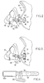
- - la figure 3, similaire à la figure 2, montre une autre variante encore ;
- - la figure 4 est une vue de détail à grande échelle montrant la constitution de la biellette de la figure 3 et de la partie de l'organe de raccordement qui en est solidaire ;
- - la figure 5 montre schématiquement une autre constitution possible de biellette du dispositif suivant l'invention ;
- - la figure 6 montre schématiquement une constitution de dispositif constituant encore un autre mode de réalisation.
- - Figure 1 is a simplified overview showing a helmet and the shell of a mask according to the invention connected to the helmet by a device according to a first embodiment;
- - Figure 2 is an elevational view showing a mask connected by a device according to an alternative embodiment to a helmet of which only a fraction is shown;
- - Figure 3, similar to Figure 2, shows yet another variant;
- - Figure 4 is a detail view on a large scale showing the constitution of the link of Figure 3 and the part of the connecting member which is integral therewith;
- - Figure 5 shows schematically another possible constitution of link of the device according to the invention;
- - Figure 6 schematically shows a device constitution constituting yet another mode of production.
Le dispositif montré schématiquement en figure 1 est destiné à fixer la coquille 10 d'un masque respiratoire sur la coque rigide 12 d'un casque d'aviateur. Le casque représenté a une constitution classique : il comprend, à l'intérieur de la coque 12 munie d'un rembourrage 14, une coiffe 16 destinée à s'appliquer sur le crâne du porteur. Une visière 18 est déplaçable, par basculement commandé à l'aide de manettes 20, entre une position haute où elle est montrée en 18 sur la figure 1 et une position basse où elle vient s'appuyer contre la coquille 10.The device shown schematically in Figure 1 is intended to fix the
Le dispositif de fixation suivant l'invention comporte deux attaches disposées symétriquement par rapport au plan médian vertical de la coquille du masque. Dans le cas illustré en figure 1, chaque attache comporte une biellette 22 rigide en flexion dans un plan vertical, non extensible, articulée sur la coquille 10 du masque et sur le casque autour de deux axes 24 et 26 sensiblement parallèles au plan médian et perpendiculaires à la longueur de la biellette. Ces deux axes peuvent n'être pas exactement parallèles lorsque la biellette est vrillée pour tenir compte de la forme évasée de la coquille du couvre face. Une extrémité de la biellette est pour cela raccordée par un axe 24 à un raccord 28. Dans le mode de réalisation représenté, ce raccord 28 est monté sur la coquille 10, par exemple par un rivet, de façon à pouvoir tourner autour d'un axe 30 perpendiculaire à l'axe 24 et dirigé vers le plan médian. L'autre extrémité de la biellette est articulée autour de l'axe 26 sur un composant d'un organe 32 de raccordement à insertion et enlèvement rapide.The fixing device according to the invention comprises two fasteners arranged symmetrically relative to the vertical median plane of the mask shell. In the case illustrated in FIG. 1, each fastener comprises a
L'organe 32 peut notamment être du type décrit dans le document US-A-4 575 375. Cet organe comporte alors un réceptacle 34 fixé rigidement à la coque 12 du casque et un ensemble insérable dans le réceptacle. La biellette est articulée autour de l'axe 26 sur une baïonnette 36 appartenant, avec une lame de commande 38, à l'ensemble. La baïonnette 36 comporte une double crémaillère prévue pour pouvoir être enfoncée dans le réceptacle 34 par simple poussée et permettre un réglage pas à pas. Elle ne peut être retirée que par traction sur un rebord 40 de la lame de commande 38.The
On voit que les biellettes se raccordent à la coquille 10 du masque à un niveau qui est pratiquement celui des forces de pression qui tendent à soulever le masque en cas de surpression à l'intérieur. En conséquence, il sera dans certains cas inutile de prévoir une sangle reliant le bas de la coquille au casque. Il sera également possible dans certains d'utiliser une coquille s'arrêtant au dessus du menton au lieu de l'emboîter.It can be seen that the rods are connected to the
La biellette 22 montrée en figure 1 se présente sous forme d'une plaquette, évidée en forme de double fourche dans un but d'allègement. Cette constitution n'est pas la seule possible et d'autres seront maintenant décrites à titre d'exemples supplémentaires.The
Le mode de réalisation montré en figure 2 (où les organes correspondant à ceux de la figure 1 sont désignés par le même numéro de référence) comporte encore une coquille 10 de masque, raccordée à la chenille 42 d'alimentation en mélange respiratoire et munie d'une mentonnière 44. La biellette 22a est constituée par un anneau rectangulaire. L'organe de raccordement à insertion et enlèvement rapide comprend encore un ensemble insérable articulé sur la biellette 22a autour de l'axe 26 et un réceptacle 34 fixé sur la coque du casque par deux vis 46.The embodiment shown in FIG. 2 (where the members corresponding to those of FIG. 1 are designated by the same reference number) also comprises a
Le mode de réalisation montré en figure 3 se différencie du précédent sur deux points.The embodiment shown in Figure 3 differs from the previous in two respects.
Le réceptacle 34, au lieu d'être fixé directement sur la coque 12 est monté sur une glissière verticale 48. Deux vis 46 portés par le receptacle traversent des trous ovalisés de la glissière et s'engagent dans des trous taraudés d'une plaquette de serrage, permettant ainsi d'ajuster la position verticale du réceptacle en fonction de la morphologie de l'individu qui doit porter le casque et le masque. La baïonnette 36 est munie d'une boucle 50 de réception d'une sangle 52 destinée à retenir en place une mentonnière 44, le masque s'arrêtant cette fois au dessus du menton.The
Dans un autre mode encore de réalisation (non représenté) le masque recouvre seulement la bouche et le nez et la sangle 52 est reliée à une mentonnière séparée solidaire du casque et l'empêchant de se soulever en cas d'accélération verticale descendante.In yet another embodiment (not shown) the mask covers only the mouth and the nose and the
Enfin la figure 5 montre une biellette 22b constituée par une lame souple, généralement métallique, destinée à être fixée sur le masque par un rivet ou une vis la laissant libre de tourner autour de l'axe 30 et à être fixée rigidement ou par l'intermédiaire d'un axe à la baïonnette 36. Dans ce cas le rôle des deux axes 24 et 26 des modes de réalisation précédents est rempli par la flexibilité latérale de la lame 22b, qui doit encore rester rigide dans le sens vertical.Finally, FIG. 5 shows a connecting
Dans la variante de réalisation montrée en figure 6 où le masque et le casque ne sont pas représentés, la biellette 22c est de longeur réglable. Pour cela, elle comporte une partie femelle 54 percée d'un trou taraudé dans lequel se visse une tige filetée 56, prévue sur l'autre partie. Cette disposition est particulièrement avantageuse lorsque le masque doit s'adapter sur des casques de diverses tailles : en donnant à la biellette la longueur convenable, la baïonnette de réglage peut se trouver enfoncée à mi-longueur dans les conditions normales d'utilisation laissant ainsi une latitude d'ajustage importante. Au lieu d'utiliser un système à tige filetée et trou taraudé, le biellette peut être constituée de deux lames coulissantes l'une sur l'autre et pouvant être fixées dans des positions différentes.In the variant embodiment shown in FIG. 6 where the mask and the helmet are not shown, the
Claims (10)
Applications Claiming Priority (2)
| Application Number | Priority Date | Filing Date | Title |
|---|---|---|---|
| FR8804616A FR2629719B1 (en) | 1988-04-07 | 1988-04-07 | DEVICE FOR FIXING A RESPIRATORY MASK ON A HELMET |
| FR8804616 | 1988-04-07 |
Publications (2)
| Publication Number | Publication Date |
|---|---|
| EP0336834A1 true EP0336834A1 (en) | 1989-10-11 |
| EP0336834B1 EP0336834B1 (en) | 1991-10-23 |
Family
ID=9365076
Family Applications (1)
| Application Number | Title | Priority Date | Filing Date |
|---|---|---|---|
| EP89400921A Expired - Lifetime EP0336834B1 (en) | 1988-04-07 | 1989-04-04 | Helmet breathing mask attachment device |
Country Status (4)
| Country | Link |
|---|---|
| US (1) | US5003632A (en) |
| EP (1) | EP0336834B1 (en) |
| DE (1) | DE68900350D1 (en) |
| FR (1) | FR2629719B1 (en) |
Cited By (4)
| Publication number | Priority date | Publication date | Assignee | Title |
|---|---|---|---|---|
| EP0720497B1 (en) * | 1993-10-01 | 1998-01-21 | Rosenbauer International Aktiengesellschaft | Protective helmet with a gas-mask attachment device |
| FR2784588A1 (en) * | 1998-10-20 | 2000-04-21 | Gallet Sa | PROTECTIVE HELMET AND ITS RESPIRATORY MASK HANGING DEVICE |
| WO2006114505A1 (en) | 2005-04-25 | 2006-11-02 | Msa Gallet | Protective helmet and its device for attaching a breathing mask |
| AU2003269736B2 (en) * | 2002-10-02 | 2007-10-04 | Fisher & Paykel Healthcare Limited | Release mechanism for masks |
Families Citing this family (37)
| Publication number | Priority date | Publication date | Assignee | Title |
|---|---|---|---|---|
| FR2686795B1 (en) * | 1992-01-30 | 1996-07-05 | Intertechnique Sa | INDIVIDUAL RESPIRATORY AND PROTECTIVE EQUIPMENT IN CONTAMINATED ATMOSPHERE. |
| FR2715572B1 (en) * | 1994-02-02 | 1996-04-26 | Intertechnique Sa | Head protection equipment with respiratory mask and optical screen. |
| US5479918A (en) * | 1994-06-30 | 1996-01-02 | Petit; James F. | Breath controller |
| AT412067B (en) * | 1994-10-24 | 2004-09-27 | Rosenbauer Oesterreich Ges M B | PROTECTIVE HELMET WITH A CONNECTING DEVICE FOR A RESPIRATORY MASK |
| FR2729058B1 (en) * | 1995-01-09 | 1997-03-14 | Gallet Sa | PROTECTIVE HELMET AND ITS CHAIN FIXING DEVICE |
| US5704073A (en) | 1995-08-01 | 1998-01-06 | Figgie International Inc. | Quick donning goggles for use with breathing mask |
| US5752298A (en) * | 1996-10-15 | 1998-05-19 | Down East, Inc. | Earcup tension adjustment strap assembly |
| CA2223345A1 (en) | 1997-12-03 | 1999-06-03 | Bombardier Inc. | Full face helmet with breathing mask |
| FR2778575B1 (en) * | 1998-05-12 | 2000-07-28 | Intertechnique Sa | RESPIRATORY PROTECTION EQUIPMENT WITH FAST SETUP |
| US6789541B2 (en) * | 2000-06-14 | 2004-09-14 | Fisher & Paykel Healthcare Limited | Breathing assistance apparatus |
| US6895960B2 (en) * | 2001-01-18 | 2005-05-24 | 3M Innovative Properties Company | Modular respirators and a method of conversion thereof |
| US6883182B2 (en) * | 2001-05-23 | 2005-04-26 | Avox Systems, Inc. | Pivot mask |
| CA2370995C (en) * | 2001-09-13 | 2010-08-17 | Fisher & Paykel Healthcare Limited | Breathing assistance apparatus |
| AU2002341458B2 (en) * | 2001-11-05 | 2007-04-05 | Fisher & Paykel Healthcare Limited | Nasal masks |
| CA2422392A1 (en) * | 2002-03-12 | 2003-09-12 | Bombardier Inc. | Cold-weather helmet with breathing mask breathing air from inside the helmet |
| ITMI20080394U1 (en) * | 2008-11-28 | 2010-05-29 | Opticos Srl | REVERSIBLE FIXING DEVICE |
| WO2010095168A1 (en) * | 2009-02-18 | 2010-08-26 | 小林文子 | Work mask wearing device and helmet using same |
| US9839252B2 (en) * | 2012-05-31 | 2017-12-12 | Bauer Hockey, Llc | Visor system for a protective sport helmet |
| US9999546B2 (en) | 2014-06-16 | 2018-06-19 | Illinois Tool Works Inc. | Protective headwear with airflow |
| US10034510B2 (en) | 2014-06-16 | 2018-07-31 | Illinois Tool Works Inc. | Headgear for protective headwear |
| US11033433B2 (en) | 2014-06-16 | 2021-06-15 | Illinois Tool Works Inc | Removable shield for protective headwear |
| US10702003B2 (en) | 2014-12-26 | 2020-07-07 | Illinois Tool Works Inc. | Apparatus for reducing angular velocity of protective shells associated with protective headwear |
| USD776359S1 (en) | 2015-05-12 | 2017-01-10 | Illinois Tool Works Inc. | Protective helmet |
| USD769543S1 (en) | 2015-05-12 | 2016-10-18 | Illinois Tool Works Inc. | Protective helmet |
| USD769535S1 (en) | 2015-05-12 | 2016-10-18 | Illinois Tool Works Inc. | Protective helmet |
| USD776360S1 (en) | 2015-05-12 | 2017-01-10 | Illinois Tool Works Inc. | Protective helmet |
| USD782120S1 (en) * | 2015-05-12 | 2017-03-21 | Illinois Tool Works Inc. | Protective helmet |
| USD769542S1 (en) | 2015-05-12 | 2016-10-18 | Illinois Tool Works Inc. | Protective helmet |
| USD777987S1 (en) | 2015-05-12 | 2017-01-31 | Illinois Tool Works Inc. | Protective helmet |
| USD770689S1 (en) | 2015-05-12 | 2016-11-01 | Illinois Tool Works Inc. | Protective helmet |
| US9814622B2 (en) | 2015-06-12 | 2017-11-14 | Illinois Tool Works Inc. | Bump cap for face protection members |
| US20160360820A1 (en) | 2015-06-12 | 2016-12-15 | Illinois Tool Works Inc. | Hard Hat Adapter for a Welding Face Member |
| USD781502S1 (en) | 2016-05-20 | 2017-03-14 | Illinois Tool Works Inc. | Protective helmet |
| USD779128S1 (en) * | 2016-05-20 | 2017-02-14 | Illinois Tool Works Inc. | Protective helmet |
| US10371487B2 (en) | 2016-10-03 | 2019-08-06 | Revision Military S.A.R.L. | Helmet accessory attachment system |
| USD814707S1 (en) | 2016-10-03 | 2018-04-03 | Revision Military S.A.R.L. | Mandible guard |
| US11026468B2 (en) | 2016-10-03 | 2021-06-08 | Galvion Ltd. | Mandible guard |
Citations (6)
| Publication number | Priority date | Publication date | Assignee | Title |
|---|---|---|---|---|
| US3077880A (en) * | 1960-03-02 | 1963-02-19 | Jr William D Morton | Mask harness |
| GB1009026A (en) * | 1963-04-06 | 1965-11-03 | Normalair Ltd | Improvements in or relating to breathing mask suspension |
| US3347229A (en) * | 1965-02-23 | 1967-10-17 | Sierra Eng Co | Latch operated microphone switch for breathing mask |
| FR1509705A (en) * | 1966-02-04 | 1968-01-12 | Westland Aircraft Ltd | Improvements to devices for attaching respiratory masks |
| US3416521A (en) * | 1964-10-06 | 1968-12-17 | Westland Aircraft Ltd | Breathing mask suspension |
| EP0236240A1 (en) * | 1986-02-25 | 1987-09-09 | Drägerwerk Aktiengesellschaft | Breathing mask fixing system for protective helmet |
Family Cites Families (4)
| Publication number | Priority date | Publication date | Assignee | Title |
|---|---|---|---|---|
| US2715222A (en) * | 1951-05-21 | 1955-08-16 | Theo J Sowle | Spectacle protector |
| US2942602A (en) * | 1955-12-14 | 1960-06-28 | Henry W Seeler | Breathing mask apparatus |
| US3065747A (en) * | 1959-08-20 | 1962-11-27 | Leonard P Frieder | Mask retaining device for a helmet |
| DE3300646C1 (en) * | 1983-01-11 | 1984-07-26 | Drägerwerk AG, 2400 Lübeck | Safety helmet combined with a respirator |
-
1988
- 1988-04-07 FR FR8804616A patent/FR2629719B1/en not_active Expired - Lifetime
-
1989
- 1989-04-04 DE DE8989400921T patent/DE68900350D1/en not_active Expired - Lifetime
- 1989-04-04 EP EP89400921A patent/EP0336834B1/en not_active Expired - Lifetime
- 1989-04-07 US US07/334,509 patent/US5003632A/en not_active Expired - Lifetime
Patent Citations (6)
| Publication number | Priority date | Publication date | Assignee | Title |
|---|---|---|---|---|
| US3077880A (en) * | 1960-03-02 | 1963-02-19 | Jr William D Morton | Mask harness |
| GB1009026A (en) * | 1963-04-06 | 1965-11-03 | Normalair Ltd | Improvements in or relating to breathing mask suspension |
| US3416521A (en) * | 1964-10-06 | 1968-12-17 | Westland Aircraft Ltd | Breathing mask suspension |
| US3347229A (en) * | 1965-02-23 | 1967-10-17 | Sierra Eng Co | Latch operated microphone switch for breathing mask |
| FR1509705A (en) * | 1966-02-04 | 1968-01-12 | Westland Aircraft Ltd | Improvements to devices for attaching respiratory masks |
| EP0236240A1 (en) * | 1986-02-25 | 1987-09-09 | Drägerwerk Aktiengesellschaft | Breathing mask fixing system for protective helmet |
Cited By (6)
| Publication number | Priority date | Publication date | Assignee | Title |
|---|---|---|---|---|
| EP0720497B1 (en) * | 1993-10-01 | 1998-01-21 | Rosenbauer International Aktiengesellschaft | Protective helmet with a gas-mask attachment device |
| FR2784588A1 (en) * | 1998-10-20 | 2000-04-21 | Gallet Sa | PROTECTIVE HELMET AND ITS RESPIRATORY MASK HANGING DEVICE |
| EP0995465A1 (en) * | 1998-10-20 | 2000-04-26 | Gallet S.A. | Safety helmet and mounting arrangement for breathing mask |
| AU2003269736B2 (en) * | 2002-10-02 | 2007-10-04 | Fisher & Paykel Healthcare Limited | Release mechanism for masks |
| WO2006114505A1 (en) | 2005-04-25 | 2006-11-02 | Msa Gallet | Protective helmet and its device for attaching a breathing mask |
| FR2902018A1 (en) | 2005-04-25 | 2007-12-14 | Msa Gallet Sa | PROTECTIVE HELMET AND ITS HITCHING DEVICE |
Also Published As
| Publication number | Publication date |
|---|---|
| FR2629719B1 (en) | 1991-03-08 |
| EP0336834B1 (en) | 1991-10-23 |
| DE68900350D1 (en) | 1991-11-28 |
| US5003632A (en) | 1991-04-02 |
| FR2629719A1 (en) | 1989-10-13 |
Similar Documents
| Publication | Publication Date | Title |
|---|---|---|
| EP0336834B1 (en) | Helmet breathing mask attachment device | |
| EP0645164B1 (en) | Respiratory protection equipment with rapid positioning | |
| EP0236240B1 (en) | Breathing mask fixing system for protective helmet | |
| EP0628325B1 (en) | Breathing protection equipment | |
| EP2299857B1 (en) | Helmet attachment platform | |
| EP3466493A1 (en) | Harness | |
| US4677713A (en) | Oronasal mask assemblies | |
| FR2633160A1 (en) | HELMET OF PROTECTION IN SEVERAL PARTS | |
| US10509239B2 (en) | Accessory mount for goggles | |
| FR2774561A1 (en) | IMPROVEMENT FOR MEANS OF HOLDING A PROTECTIVE HELMET | |
| FR2712465A1 (en) | Assembly kit for aeronaut helmet equipment. | |
| FR3043215A1 (en) | SYSTEM FOR VISUALIZING AND AUDIO COMMUNICATION GIVEN BY THE HEAD OF A USER COMPRISING A DEVICE FOR MAINTAINING RETRACTABLE NUQUE | |
| EP3355996B1 (en) | Aircraft cockpit, assembly comprising a respiratory mask and a storage device, as well as storage method and method for use of such an assembly | |
| US5857599A (en) | Mounting bracket assembly for a night vision device | |
| EP1895865B1 (en) | Device for fixing a visor to a helmet shell | |
| EP0878211B1 (en) | Individual protection equipment against NBC attacks | |
| FR2800173A1 (en) | Spectacle frame has hinged bridge-piece which can be opened to allow lenses to be removed, replaced or changed | |
| FR2945221A1 (en) | Safety harness i.e. tie-in, for use during elevation work, has male and female bodies connected together by lock mechanism in closed position of automatic closing buckle, where female body carries fastening ring for fixing safety line | |
| EP0371858A1 (en) | Individual respiratory and contamined environment protective equipment | |
| FR2463626A1 (en) | Respirator headgear for aircrew - has lever pivotally mounted on face mask and cooperating with arms operative to pinch wearer's nose | |
| FR2508777A1 (en) | Protective helmet with press studs for fixing accessories - has part of stud fixed to accessory fitted adjustably in slots with angled cut=outs | |
| FR2854575A1 (en) | Respiratory mask fixing device for use by e.g. fireman, has carriage comprising hook cooperating with mooring notch fixed on hull of helmet, and lever cooperating with toothed bar | |
| FR2700747A1 (en) | Head gear for an aircraft pilot | |
| FR2812819A1 (en) | Face mask for respirator has rigid shell with gas feed duct and flexible lip seal with adjustable mounting | |
| FR2668374A1 (en) | Device to enable a breathing mask to be worn |
Legal Events
| Date | Code | Title | Description |
|---|---|---|---|
| PUAI | Public reference made under article 153(3) epc to a published international application that has entered the european phase |
Free format text: ORIGINAL CODE: 0009012 |
|
| AK | Designated contracting states |
Kind code of ref document: A1 Designated state(s): DE GB IT SE |
|
| 17P | Request for examination filed |
Effective date: 19891228 |
|
| 17Q | First examination report despatched |
Effective date: 19910325 |
|
| GRAA | (expected) grant |
Free format text: ORIGINAL CODE: 0009210 |
|
| AK | Designated contracting states |
Kind code of ref document: B1 Designated state(s): DE GB IT SE |
|
| GBT | Gb: translation of ep patent filed (gb section 77(6)(a)/1977) | ||
| REF | Corresponds to: |
Ref document number: 68900350 Country of ref document: DE Date of ref document: 19911128 |
|
| ITF | It: translation for a ep patent filed |
Owner name: UFFICIO TECNICO ING. A. MANNUCCI |
|
| PLBI | Opposition filed |
Free format text: ORIGINAL CODE: 0009260 |
|
| 26 | Opposition filed |
Opponent name: DRAEGERWERK AKTIENGESELLSCHAFT Effective date: 19920617 |
|
| EAL | Se: european patent in force in sweden |
Ref document number: 89400921.6 |
|
| PLBN | Opposition rejected |
Free format text: ORIGINAL CODE: 0009273 |
|
| STAA | Information on the status of an ep patent application or granted ep patent |
Free format text: STATUS: OPPOSITION REJECTED |
|
| 27O | Opposition rejected |
Effective date: 19930514 |
|
| REG | Reference to a national code |
Ref country code: GB Ref legal event code: IF02 |
|
| PGFP | Annual fee paid to national office [announced via postgrant information from national office to epo] |
Ref country code: GB Payment date: 20050406 Year of fee payment: 17 |
|
| PGFP | Annual fee paid to national office [announced via postgrant information from national office to epo] |
Ref country code: DE Payment date: 20050429 Year of fee payment: 17 |
|
| PGFP | Annual fee paid to national office [announced via postgrant information from national office to epo] |
Ref country code: SE Payment date: 20050502 Year of fee payment: 17 |
|
| APAH | Appeal reference modified |
Free format text: ORIGINAL CODE: EPIDOSCREFNO |
|
| PG25 | Lapsed in a contracting state [announced via postgrant information from national office to epo] |
Ref country code: GB Free format text: LAPSE BECAUSE OF NON-PAYMENT OF DUE FEES Effective date: 20060404 |
|
| PG25 | Lapsed in a contracting state [announced via postgrant information from national office to epo] |
Ref country code: SE Free format text: LAPSE BECAUSE OF NON-PAYMENT OF DUE FEES Effective date: 20060405 |
|
| PGFP | Annual fee paid to national office [announced via postgrant information from national office to epo] |
Ref country code: IT Payment date: 20060430 Year of fee payment: 18 |
|
| PG25 | Lapsed in a contracting state [announced via postgrant information from national office to epo] |
Ref country code: DE Free format text: LAPSE BECAUSE OF NON-PAYMENT OF DUE FEES Effective date: 20061101 |
|
| EUG | Se: european patent has lapsed | ||
| GBPC | Gb: european patent ceased through non-payment of renewal fee |
Effective date: 20060404 |
|
| PG25 | Lapsed in a contracting state [announced via postgrant information from national office to epo] |
Ref country code: IT Free format text: LAPSE BECAUSE OF NON-PAYMENT OF DUE FEES Effective date: 20070404 |