EP0336761A2 - Lageermittlungsvorrichtung mit Mittel zum Umschalten mehrerer Wechselsignale mit verschiedenen Phasen - Google Patents
Lageermittlungsvorrichtung mit Mittel zum Umschalten mehrerer Wechselsignale mit verschiedenen Phasen Download PDFInfo
- Publication number
- EP0336761A2 EP0336761A2 EP89303423A EP89303423A EP0336761A2 EP 0336761 A2 EP0336761 A2 EP 0336761A2 EP 89303423 A EP89303423 A EP 89303423A EP 89303423 A EP89303423 A EP 89303423A EP 0336761 A2 EP0336761 A2 EP 0336761A2
- Authority
- EP
- European Patent Office
- Prior art keywords
- signal
- phase
- output
- point
- voltage
- Prior art date
- Legal status (The legal status is an assumption and is not a legal conclusion. Google has not performed a legal analysis and makes no representation as to the accuracy of the status listed.)
- Ceased
Links
Images


Classifications
-
- G—PHYSICS
- G11—INFORMATION STORAGE
- G11B—INFORMATION STORAGE BASED ON RELATIVE MOVEMENT BETWEEN RECORD CARRIER AND TRANSDUCER
- G11B21/00—Head arrangements not specific to the method of recording or reproducing
- G11B21/02—Driving or moving of heads
-
- G—PHYSICS
- G11—INFORMATION STORAGE
- G11B—INFORMATION STORAGE BASED ON RELATIVE MOVEMENT BETWEEN RECORD CARRIER AND TRANSDUCER
- G11B17/00—Guiding record carriers not specifically of filamentary or web form, or of supports therefor
- G11B17/34—Guiding record carriers during transducing operation, e.g. for track following
-
- G—PHYSICS
- G11—INFORMATION STORAGE
- G11B—INFORMATION STORAGE BASED ON RELATIVE MOVEMENT BETWEEN RECORD CARRIER AND TRANSDUCER
- G11B21/00—Head arrangements not specific to the method of recording or reproducing
- G11B21/02—Driving or moving of heads
- G11B21/08—Track changing or selecting during transducing operation
-
- G—PHYSICS
- G11—INFORMATION STORAGE
- G11B—INFORMATION STORAGE BASED ON RELATIVE MOVEMENT BETWEEN RECORD CARRIER AND TRANSDUCER
- G11B7/00—Recording or reproducing by optical means, e.g. recording using a thermal beam of optical radiation by modifying optical properties or the physical structure, reproducing using an optical beam at lower power by sensing optical properties; Record carriers therefor
- G11B7/08—Disposition or mounting of heads or light sources relatively to record carriers
- G11B7/085—Disposition or mounting of heads or light sources relatively to record carriers with provision for moving the light beam into, or out of, its operative position or across tracks, otherwise than during the transducing operation, e.g. for adjustment or preliminary positioning or track change or selection
- G11B7/08505—Methods for track change, selection or preliminary positioning by moving the head
-
- G—PHYSICS
- G11—INFORMATION STORAGE
- G11B—INFORMATION STORAGE BASED ON RELATIVE MOVEMENT BETWEEN RECORD CARRIER AND TRANSDUCER
- G11B7/00—Recording or reproducing by optical means, e.g. recording using a thermal beam of optical radiation by modifying optical properties or the physical structure, reproducing using an optical beam at lower power by sensing optical properties; Record carriers therefor
- G11B7/08—Disposition or mounting of heads or light sources relatively to record carriers
- G11B7/085—Disposition or mounting of heads or light sources relatively to record carriers with provision for moving the light beam into, or out of, its operative position or across tracks, otherwise than during the transducing operation, e.g. for adjustment or preliminary positioning or track change or selection
- G11B7/0857—Arrangements for mechanically moving the whole head
- G11B7/08582—Sled-type positioners
Definitions
- the present invention relates to a position detecting device for obtaining desplacement information of a movable member and more particularly, to a position detecting device for obtaining displacement information suitable for slowly moving an optical head or an information recording medium in, e.g., an optical information recording/reproducing apparatus.
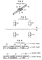
- Fig. 1 is a block diagram showing a main part of a conventional optical disk apparatus.
- a light emitted from a laser diode 20 is collimated by a collimation lens 19, and the collimated light ray is reflected by a mirror 13 through a polarizing beam splitter 44 and is focused on a recording layer of an optical disk 10 through an objective lens 12.
- the reflected light from the optical disk 10 is reflected again by the mirror 13 through the objective lens 12.
- the reflected light is then reflected downward by the polarizing beam splitter 44.
- One partially reflected by a half mirror 15 is detected by a photodetector 18 through a lens 17, and the detected optical information is input to a radio-frequency (RF) signal amplifier 23.
- the other passing through the half mirror 15 is detected by a four-split beam detector 16.
- An output from the detector 16 is input to a position error signal processing circuit 25.
- An output from the position error signal processing circuit 25 is input to a focusing/tracking servo circuit 21, and an output from the servo circuit 21 is used to finely adjust the objective lens 12.
- a voice coil motor (VCM) servo circuit 24 controls to move an optical head 11 to a position near a desired track and stop it on the desired track in accordance with track selection data from a microprocessor unit (MPU) 27.
- the MPU 27 controls a spindle motor 29 for rotating the optical disk 10 by using a spindle motor servo circuit 26 and an encoder 28.
- the MPU 27 also controls emission of the laser diode 20 through a laser driver 22.
- a linear encoder shown in Fig. 2 is arranged between the optical head 11 and a housing 45.
- a movable slit member 31 is engaged with the optical head 11 and is moved together with the optical head 11.
- a stationary slit member 30, light emitting diodes (LEDs) 32 and 33, and phototransistors (PTr) 34 and 35 are fixed on the housing 45.
- the positional relationship between the movable slit member 31, the stationary slit member 30, the LEDs 32 and 33, and the PTrs 34 and 35 is illustrated in Fig. 3. That is, the LED 32 opposes the PTr 34, and the LED 33 opposes the PTr 35.
- phase of fixed slit between the LED 32 and the PTr 34 is shifted from that of the fixed slit between the LED 33 and PTr 35 by 90°.
- Outputs from the PTrs 34 and 35 are input to current-voltage converters 36 and 37, and outputs from the current-voltage converters 36 and 37 are partially input to inverting amplifiers 38 and 39, as shown in Fig. 4, to obtain four phase alternating signals phase-shifted from each other by 90° as shown in Fig. 5.
- a spiral groove (track) called a pregroove is formed in the optical disk beforehand to perform tracking guide.
- the optical head for example, is controlled to be stopped at the A point of the first phase of Fig. 5, and the position of the objective lens is controlled to trace the spiral track.
- the objective lens is moved by an actuator (not shown) in the tracking direction. Since the range of displacement of the objective lens is limited, the entire optical head is moved to control the objective lens so as not to be out from the above displacement range.
- Fig. 6 is a conventional position control block diagram of an optical head using a voice coil motor.
- a difference between a target value and displacement information from a position detecting device 40 using the linear encoder as described above is input to a phase compensator 41, and a predetermined current is supplied to a voice coil motor 43 through a driver 42, thereby moving the optical head.
- the voice coil motor 43 does not normally have stress such as a spring property in a movable direction, when a motor current is zero, the optical head is stopped at an arbitrary position. For this reason, when the target value in Fig. 6 is set to be 0 (V), the position of the optical head is controlled to the A point of the first phase.
- a position control output from the linear encoder is changed from an output of the first phase to an output of the second phase.
- the operating point reaches the D point in an order of A, B, C, and D in Fig. 5.
- a position control output from the linear encoder is changed from the output of the second phase to an output of the third phase under the condition where the position of the optical head is controlled at the position D.
- the operating point reaches the G point in an order of D,E, F, and G. In this manner, the optical head is sequentially fed.
- the optical disk apparatus When the optical disk apparatus receives external impact, vibrations in an optical head feed direction, the optical head is braked to a control position by position control. If a control gain is kept unchanged, resistance to impact and vibrations is associated with a detection region of the position detecting device. Assume that external impact acts in the optical head feed direction while the position of the optical head is controlled to the D point of the second phase in Fig. 5. The operating point is shifted to the left and right along a curve of the second phase by an impact force. At this time, during movement of the optical head in an order of D, C, and B, or D, H, and I, the amplitude is increased with an increase in displacement, so that a restoration force is increased accordingly.
- the restoration force is decreased.
- the optical head When the optical head is moved over the M point to the left or over the K point to the right, it falls within a positive feedback region and therefore is quickly moved to the N point away from the point D of the curve of the second phase by one period and to a point (not shown) to the right of the point O by one step. In this state, tracking servo control is adversely affected, and a stop position of the optical head cannot be determined by position control, resulting in inconvenience.
- a position detecting device comprising: means for generating a plurality of phase-shifted signals which are alternately changed in accordance with changes in position or angle of the movable member; means for selecting one of the plurality of signals; means for supplying a variable level signal; means for adding a signal selected by the selecting means and the variable level signal from the signal supplying means and outputting a sum signal as a position detection signal; means for detecting a phase of the selected signal; and control means for switching the signal selected by the selecting means and changing a level of the variable level signal from the signal supplying means in accordance with an output from the phase detecting means.
- a linear encoder is arranged between an optical head main body and a housing of an optical disk apparatus, and an arrangement thereof is shown in Figs. 1, 2, 3, 4, and 6 in the same manner as in the conventional case.
- a graph shown in Fig. 8 is used in place of that in Fig. 5.
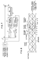
- Fig. 7 is a block diagram of a position detection device according to the first embodiment.
- a multiplexer 1 selects one of signals having the first to fourth phases. The first to fourth phases correspond to those in Figs. 4 and 5.
- the multiplexer 1 generates an output VS.
- Voltage comparators 2 and 3 have reference voltages Vref1 and Vref2, respectively.
- An output C1 from the voltage comparator 2 is input to the DEC terminals of first and second counters 5 and 4.
- the counters 4 and 5 are decremented at a leading edge of the output C1.
- An output C2 from the voltage comparator 3 is input to the INC terminals of the counters 4 and 5.
- the counters are incremented at a leading edge of the output C2.
- the first counter 5 is a 2-bit up/down counter capable of taking values 1, 2, 3, and 4 and repeats an incrementing operation in an order of 1, 2, 3, 4, 1.
- the multiplexer 1 selects a phase signal corresponding to the content of the counter 5 and generates the selected phase signal as the output VS. For example, if the content of the counter 5 is 2, the signal of the second phase serves as the output VS from the multiplexer 1.
- the second counter 4 is also an up/down counter and takes values in the range of -2, -1, 0, 1, and 2.
- the content of the counter 4 is converted into a voltage VD by a digital-to-analog (DA) converter 6.
- DA digital-to-analog
- VD is added to the output VS from the multiplexer 1 by an adder 7.
- the counters 5 and 4 are incremented, and their contents are updated to 3 and 1, respectively. For this reason, a phase selected by the multiplexer 1 is changed to the third phase.
- K is selected to be a voltage value corresponding to a potential difference between the a and a′ points. Therefore, the operating point is smoothly shifted from the a point to the a′ point.
- the optical head is greatly vibrated and is further moved to the right, the optical head is moved from the a′ point to the right along the curve of the third phase, and the phase is changed to the fourth phase in the same manner as described above.
- the phase at the a′ point is kept unchanged.
- the output C1 from the voltage comparator 2 rises at the b point. That is, the reference voltage Vref1 is set to be equal to the alternating signal voltage at the b point. Therefore, the counters 5 and 4 are decremented to 2 and 0, respectively.
- the voltage value is given as K. Therefore, the operating point is smoothly shifted from the b point to the b′ point.
- the optical head is moved from the b′ point to the left along the curve of the second phase. Bidirectional switching is not performed at points such as the a′ and b′ points to provide hysteresis for preventing oscillation and stabilizing the operation.
- the phase is changed at the C point.
- the phase is changed at the d point.
- a monotonous increase region for position detection can be equivalently increased, and resistance to external vibrations and impact can be greatly increased during position control.
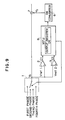
- Fig. 9 is a block diagram of a position detection device according to the second embodiment.
- the device is substantially the same as that of the first embodiment except that the counters 5 and 4 are replaced with a general-purpose microprocessor unit (MPU) 8.
- MPU general-purpose microprocessor unit
- Fig. 10 is a flow chart of an operation in which an optical head is gradually moved by using the MPU 8.
- the MPU 8 includes an output register OR for outputting a signal to a DA converter 6.
- steps S1 and S2 are performed to set a position control target value to 0 V.
- step S3 a lag time of 1 mS is allowed to pass.
- steps S4 and S5 the DA converter output VD serving as the target value is decreased by one count of the output register OR. That is, the content of the output register OR is decremented by one.
- the one count VD value is set to be 1/64 of the voltage value K between the a and a′ points.
- steps S6 and S7 rising of outputs C1 and C2 from voltage comparators 2 and 3 is determined. Since no rising occurs, the flow returns to step S3.
- the operations in steps S3 to S7 are repeated and the content of the output register OR is decremented one by one when the operating point is shifted between the D point and the a point.
- YES is obtained in step S7, and the flow advances to step S8.
- Vref2 -K/2 - 3K/64 and the count of the output register OR which corresponds to K is 64. Therefore, the count required to shift the operating point from the D point to the a point is 35, i.e., the corresponding content of the output register OR is -35.
- step S8 a value corresponding to the second phase is incremented by one to select the third phase.
- step S3 returns to step S3 again, and the operations in steps S3 to S7 are repeated, so that the operating point reaches the point G.
- the optical head is further shifted to the right, the above operations are repeated by using the G point as an initial point.
- step S6 When the D point is used as an initial operating point to shift the optical head to the left, and the content of the output register OR is incremented in step S4 of Fig. 10, YES is obtained in step S6 when the operating point reaches the C point.
- steps S11 to S13 are performed. As is easily understood from the previous explanation, these operations are for moving the operating point from the c point to the c′ point.
- the encoder phases are sequentially switched to gradually move the optical head. That is, since the target value is gradually changed upon phase switching, optical head feeding without an excessive increase in acceleration which is caused by phase switching can be achieved.
- steps S8 to S10 or S11 to S13 are performed when the operating point crosses the a , b , c , and d points, thereby equivalently increasing the monotonous increase region of position detection in the same manner as in the first embodiment.
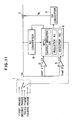
- Fig. 11 is a block diagram of a position detecting device according to the third embodiment.
- the position detecting device of the third embodiment is substantially the same as that of Fig. 9, except that an output VS from a multiplexer 1 is converted into digital data by an analog-to-digital (AD) converter 9, and the digital data is input to an MPU 8.
- AD analog-to-digital
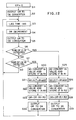
- Fig. 12 is a flow chart for explaining an operation for gradually moving an optical head by the arrangement of the third embodiment.
- the operations in steps S8 to S10 and S11 to S13 in Fig. 10 are replaced with operations in steps S20 to S24 and S25 to S29.
- Position control during movement of the optical head is exemplified in the above embodiments.
- the present invention may be used to perform position control during linear or circular movement of an optical disk.
- the present invention may be utilized for apparatuses for performing optical head position control or optical card position control in an optical card apparatus, similar control in an optomagnetic disk apparatus, and the like.
- the present invention can also be applied to apparatuses except for optical information processing apparatuses.
- phases of the alternating signals are detected by the voltage comparators 2 and 3.
- a signal of an ⁇ phase may be formed by adding the signals of the first and second phases and a signal of a ⁇ phase may be formed by adding the signals of the second and third phases to detect a phase of the alternating signal by the voltage comparators 2 and 3 upon detection of a zero-crossing point of each signal of the ⁇ or ⁇ phase, thereby obtaining the same effect as described above.
Landscapes
- Moving Of The Head For Recording And Reproducing By Optical Means (AREA)
- Transmission And Conversion Of Sensor Element Output (AREA)
Applications Claiming Priority (2)
| Application Number | Priority Date | Filing Date | Title |
|---|---|---|---|
| JP63084024A JPH01257213A (ja) | 1988-04-07 | 1988-04-07 | 位置検出装置 |
| JP84024/88 | 1988-04-07 |
Publications (2)
| Publication Number | Publication Date |
|---|---|
| EP0336761A2 true EP0336761A2 (de) | 1989-10-11 |
| EP0336761A3 EP0336761A3 (en) | 1990-07-18 |
Family
ID=13818994
Family Applications (1)
| Application Number | Title | Priority Date | Filing Date |
|---|---|---|---|
| EP89303423A Ceased EP0336761A3 (en) | 1988-04-07 | 1989-04-06 | Position detecting device for use by switching plural alternating signals having different phases from each other |
Country Status (3)
| Country | Link |
|---|---|
| US (1) | US5067118A (de) |
| EP (1) | EP0336761A3 (de) |
| JP (1) | JPH01257213A (de) |
Cited By (1)
| Publication number | Priority date | Publication date | Assignee | Title |
|---|---|---|---|---|
| US6013431A (en) * | 1990-02-16 | 2000-01-11 | Molecular Tool, Inc. | Method for determining specific nucleotide variations by primer extension in the presence of mixture of labeled nucleotides and terminators |
Families Citing this family (2)
| Publication number | Priority date | Publication date | Assignee | Title |
|---|---|---|---|---|
| TW587824U (en) * | 2003-06-06 | 2004-05-11 | Yu-Nung Shen | Compact disk and portable compact disk drive for reading data stored in the compact disk |
| US20060068364A1 (en) * | 2004-09-29 | 2006-03-30 | Struck James T | Methods and devices for the prevention and treatment of gingival recession |
Family Cites Families (10)
| Publication number | Priority date | Publication date | Assignee | Title |
|---|---|---|---|---|
| US4416002A (en) * | 1978-04-10 | 1983-11-15 | Hitachi, Ltd. | Method and apparatus for high-density recording and reproduction |
| JPS55101810A (en) * | 1979-01-30 | 1980-08-04 | Nippon Telegr & Teleph Corp <Ntt> | Deflection detector |
| GB2054135B (en) * | 1979-07-19 | 1984-03-14 | Burroughs Corp | Photo-electric displacement transducer |
| US4464689A (en) * | 1981-06-04 | 1984-08-07 | Education & Informations Systems, Inc. | Random access read/write unit |
| US4443869A (en) * | 1981-09-28 | 1984-04-17 | Rca Corporation | Track jump servo system for disc player |
| US4510537A (en) * | 1982-05-04 | 1985-04-09 | Computer Basic Technology Research Assoc. | Magnetic head moving velocity detector |
| JPS5940378A (ja) * | 1982-08-31 | 1984-03-06 | Toshiba Corp | デイスク装置 |
| US4590527A (en) * | 1983-11-14 | 1986-05-20 | Burroughs Corporation | Positioning servomechanisms |
| JPS637571A (ja) * | 1986-06-27 | 1988-01-13 | Nec Corp | 磁気デイスク装置 |
| JPS6468814A (en) * | 1987-09-10 | 1989-03-14 | Canon Kk | Method and device for position control of moving object |
-
1988
- 1988-04-07 JP JP63084024A patent/JPH01257213A/ja active Pending
-
1989
- 1989-04-06 US US07/334,195 patent/US5067118A/en not_active Expired - Lifetime
- 1989-04-06 EP EP89303423A patent/EP0336761A3/en not_active Ceased
Cited By (1)
| Publication number | Priority date | Publication date | Assignee | Title |
|---|---|---|---|---|
| US6013431A (en) * | 1990-02-16 | 2000-01-11 | Molecular Tool, Inc. | Method for determining specific nucleotide variations by primer extension in the presence of mixture of labeled nucleotides and terminators |
Also Published As
| Publication number | Publication date |
|---|---|
| JPH01257213A (ja) | 1989-10-13 |
| US5067118A (en) | 1991-11-19 |
| EP0336761A3 (en) | 1990-07-18 |
Similar Documents
| Publication | Publication Date | Title |
|---|---|---|
| US4914725A (en) | Transducer positioning servo mechanisms employing digital and analog circuits | |
| EP0227044B1 (de) | Gerät für optische Platten | |
| EP0414450B1 (de) | Antriebseinheiten für optische Platte | |
| US5978328A (en) | Focus control device to perform focus control for a multi-layer recording medium | |
| US4819219A (en) | Track jump control system for optical disk apparatus | |
| JP2759686B2 (ja) | 記録担体を走査する装置 | |
| CA2244961C (en) | Closed loop servo operation for focus control | |
| US4513406A (en) | Positioning servo circuit for a disk system | |
| KR950001873B1 (ko) | 광디스크 고속탐색 제어장치 및 방법 | |
| EP0336761A2 (de) | Lageermittlungsvorrichtung mit Mittel zum Umschalten mehrerer Wechselsignale mit verschiedenen Phasen | |
| EP0249462A1 (de) | Gerät zur Wiedergabe von Platten | |
| US7170833B2 (en) | Apparatus for scanning optical recording media using DPD tracking method with analog and digital delay elements | |
| US5291464A (en) | Speed and position control apparatus for positioning a movable object | |
| JPH0520829B2 (de) | ||
| US6326756B1 (en) | Method and apparatus for applying a driving voltage to a motor of an optical disk device | |
| KR100425465B1 (ko) | 광 디스크 재생 시스템에서 브레이크 능력을 향상시키는브레이크 신호 발생회로 및 방법 | |
| US5103440A (en) | Track access error correction apparatus for moving an optical head from one track location to another track location on an optical disc | |
| JP2606490B2 (ja) | 可動体の位置制御装置 | |
| JP2521270B2 (ja) | 磁気ヘツドの位置決め方法 | |
| JP2913126B2 (ja) | 光ディスクのアクセス装置 | |
| JPH10275340A (ja) | フォーカス制御装置 | |
| JPH02278482A (ja) | 割算回路 | |
| JPH0778344A (ja) | 光ディスクプレーヤーのトラックカウント回路 | |
| JPH0290213A (ja) | 位置検出装置 | |
| JPS63204569A (ja) | ヘツド位置決め装置 |
Legal Events
| Date | Code | Title | Description |
|---|---|---|---|
| PUAI | Public reference made under article 153(3) epc to a published international application that has entered the european phase |
Free format text: ORIGINAL CODE: 0009012 |
|
| AK | Designated contracting states |
Kind code of ref document: A2 Designated state(s): DE FR GB NL |
|
| PUAL | Search report despatched |
Free format text: ORIGINAL CODE: 0009013 |
|
| AK | Designated contracting states |
Kind code of ref document: A3 Designated state(s): DE FR GB NL |
|
| RHK1 | Main classification (correction) |
Ipc: G11B 7/08 |
|
| 17P | Request for examination filed |
Effective date: 19901210 |
|
| 17Q | First examination report despatched |
Effective date: 19930301 |
|
| STAA | Information on the status of an ep patent application or granted ep patent |
Free format text: STATUS: THE APPLICATION HAS BEEN REFUSED |
|
| 18R | Application refused |
Effective date: 19940623 |