EP0336743B1 - Optisches Abtastsystem - Google Patents
Optisches Abtastsystem Download PDFInfo
- Publication number
- EP0336743B1 EP0336743B1 EP89303382A EP89303382A EP0336743B1 EP 0336743 B1 EP0336743 B1 EP 0336743B1 EP 89303382 A EP89303382 A EP 89303382A EP 89303382 A EP89303382 A EP 89303382A EP 0336743 B1 EP0336743 B1 EP 0336743B1
- Authority
- EP
- European Patent Office
- Prior art keywords
- mirror
- deflector
- light beam
- optical system
- scanning optical
- Prior art date
- Legal status (The legal status is an assumption and is not a legal conclusion. Google has not performed a legal analysis and makes no representation as to the accuracy of the status listed.)
- Expired - Lifetime
Links
- 230000003287 optical effect Effects 0.000 title claims description 17
- 230000015572 biosynthetic process Effects 0.000 description 5
- 238000004519 manufacturing process Methods 0.000 description 2
- 230000015556 catabolic process Effects 0.000 description 1
- 230000000052 comparative effect Effects 0.000 description 1
- 238000006731 degradation reaction Methods 0.000 description 1
- 230000010355 oscillation Effects 0.000 description 1
Images


Classifications
-
- H—ELECTRICITY
- H04—ELECTRIC COMMUNICATION TECHNIQUE
- H04N—PICTORIAL COMMUNICATION, e.g. TELEVISION
- H04N3/00—Scanning details of television systems; Combination thereof with generation of supply voltages
- H04N3/02—Scanning details of television systems; Combination thereof with generation of supply voltages by optical-mechanical means only
- H04N3/08—Scanning details of television systems; Combination thereof with generation of supply voltages by optical-mechanical means only having a moving reflector
-
- G—PHYSICS
- G02—OPTICS
- G02B—OPTICAL ELEMENTS, SYSTEMS OR APPARATUS
- G02B26/00—Optical devices or arrangements for the control of light using movable or deformable optical elements
- G02B26/08—Optical devices or arrangements for the control of light using movable or deformable optical elements for controlling the direction of light
- G02B26/10—Scanning systems
Definitions
- the present invention relates to a scanning optical system and a scanning optical apparatus for performing data recording on a surface to be scanned using the scanning optical system.
- a deflector used in a scanning optical system adopts a polygonal mirror in which a deflection velocity of a light beam is equiangular or a galvano mirror (sinusoidal oscillation mirror) in which a deflection velocity of a light beam is not equiangular.
- GB-A-2185167 discloses an example of a system using a rotating polygonal mirror.
- US-A-4627685 and EP-A-0214863 disclose examples of systems using an oscillating mirror.
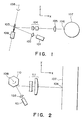
- Figs. 1 to 3 are schematic views showing general arrangements of a scanning optical apparatus using a scanning system. For the sake of simplicity, a description will be made while an optical system for inclination correction is not necessary.
- Fig. 1 shows an example wherein a galvano mirror is used as the deflector.
- a light beam emitted from a light source 101 is collimated to a parallel beam by a collimator lens 102, and the parallel beam is incident on a mirror surface of a galvano mirror 103.
- the beam is reflected by the mirror surface, passes through an arcsine lens 104, and forms an image on a surface 106 to be scanned through a cylindrical lens 105.
- a photosensitive drum 107 for recording the light source is located at the surface 106.
- the light beam becomes incident on the galvano mirror 103 within a plane perpendicular to the surface 106 and including a pivot axis 108 of the deflector (this plane will be referred to as a z-x plane under an assumption that a coordinate system shown in Fig. 1 is given for the sake of simplicity).
- the cylindrical lens 105 is inserted for the purpose of correcting a curve of an image surface to be scanned in a z direction during rotation of the mirror surface. Note that in Fig. 1, 109 indicates a driver for the galvano mirror 103.
- Fig. 2 shows an example wherein a polygonal mirror is used as the deflector.
- a light beam emitted from a light source 101 is collimated to a parallel beam by a collimator lens 102, and is incident on a mirror surface of a polygonal mirror 110.
- the parallel beam is reflected by the mirror surface, and forms an image on a surface 106 to be scanned through an f- ⁇ lens 111.
- the light beam becomes incident on the polygonal mirror 110 within a plane perpendicular to the surface 106 and a pivot axis 108 of the deflector. This plane is called a y-x plane for the sake of descriptive convenience.
- Fig. 3 shows another example wherein a polygonal mirror is used as the deflector.
- a light beam emitted from a light source 101 is collimated into a parallel beam by a collimator lens 102, and is incident on the mirror surface of a polygonal mirror 110.
- the parallel beam is reflected by the mirror surface, and is imaged onto the surface 106 to be scanned through an f- ⁇ lens 111 and a cylindrical lens 105.
- a laser beam becomes incident on the polygonal mirror 110 within the z-x plane.
- the cylindrical lens 105 is inserted for the purpose of correcting a curve of an image surface to be scanned in a z direction during rotation of the mirror surface.
- 112 indicates a driver for the polygonal mirror 110.
- a curve of an image surface caused by scanning a light beam upon pivotal movement of the mirror surface of the deflector must be corrected, and a scanning speed of an image on the surface to be scanned by pivotal movement of the deflector must be rendered constant.
- a plurality of lens systems are required. These lens systems are generally difficult to design, have complicated structures, and hence are expensive. For this reason, the direction of a light beam reflected by the mirror surface is preferably symmetrical within a single plane.
- the cylindrical lens 105 When the light beam is incident on the mirror surface from a point within the z-x plane like in Figs. 1 and 3, symmetricity of the light beam to be reflected can be assured.
- the cylindrical lens 105 since the image surface of the light beam to be scanned is curved in the z direction upon rotation of the mirror surface, the cylindrical lens 105 must be arranged so as to correct the curve.
- the cylindrical lens is also used for correcting an inclination error of the mirror surface.
- the curve in the z direction is larger than the influence caused by an inclination of an angle of the mirror surface, design, manufacture, and adjustment of the cylindrical lens are generally difficult, and this also makes the f- ⁇ lens and arcsin ⁇ lens difficult to design as well as the cylindrical lens.
- JP-A-58-189609 discloses a light beam scanner using a regular polygon mirror which rotates about an axis of rotation, the axis of the polygon mirror crossing obliquely the axis of rotation.
- the pivot axis and the mirror surface of the deflector are inclined so that a curve of an image surface of a light beam falls within an allowable range from a plane, and the pivot axis of the deflector is inclined with respect to a normal (z direction) of the deflection plane, so that a curve of the image surface of the light beam falls within the allowable range from a plane.
- the scanning surface is parallel to the z-axis.
- Fig. 4 shows the overall arrangement for explaining the principle of the present embodiments.
- an x-y-z orthogonal coordinate system is provided.
- Fig. 5 is a sectional view taken along a z-x plane in Fig. 4, and illustrates a state wherein the scanning angle (pivot angle) of a mirror is 0. That is, light beams incident on and emerging from the mirror are present within an identical plane.
- a light beam emitted from a light source is incident as an incident beam 11 at an incident angle ⁇ on a mirror surface 12 of a deflector through a collimator lens (not shown), is reflected by the mirror surface, and forms an image on a surface to be scanned.
- the light beam may pass through a lens system (not shown) used as needed between the light source and the surface to be scanned.
- the mirror surface 12 of the deflector is fixed to a pivot axis 13 of the deflector, and is pivoted about the pivot axis, thereby scanning a reflected beam 14 on the surface to be scanned.
- a photosensitive drum 16 for performing recording is placed at the surface 15 to be scanned.
- An angle defined between the pivot axis and the mirror surface will be described below with reference to Fig. 5.
- the incident beam is incident to define an angle 2 ⁇ with the x axis.
- the mirror surface is fixed to define an angle ⁇ (not 0) with the pivot axis.
- the mirror surface forms an angle ⁇ with the z axis. Therefore, the reflected beam is parallel to the x axis. If ⁇ is 0, the relationship between a direction vector of the incident beam and the normal vector of the mirror surface is changed as the mirror is pivoted, and a z component is generated in the direction vector of the reflected beam.
- the pivot center of the mirror is different from the position of the mirror surface of the incident beam, an incident position is offset in the z direction, and an image formation position is changed.
- a curve of an image formation surface in the z direction caused when the mirror is pivoted can fall within an allowable range.
- Light rays reflected by the mirror surface before they reach the surface to be scanned can fall within a range regarded as a plane.
- ⁇ took different values depending on an angle of the incident beam, a incident beam position, a curvature of the mirror surface, and a radius of pivotal movement of the mirror surface (a distance between the incident position of light rays onto the mirror surface when the scanning angle is 0° and the pivot axis).
- Tables 1 to 22 below show values ⁇ according to the present embodiments for some incident beam directions, positions of an image surface in the z direction at some scanning angles at corresponding ⁇ , and positions of the image surface in the z direction according to comparative examples.
- 2 ⁇ means an angle formed by an incident light with the x axis
- ⁇ is the angle formed by the pivot axis and the mirror surface of the deflector according to the present embodiments
- ⁇ is the pivot angle of the mirror.
- the angle ⁇ represents an angle of pivotal movement of the mirror surface pivoted about the pivot axis of the deflector.
- Tables 1 to 4 show cases wherein the mirror surface is a plane, and the radius of pivotal movement of the mirror is 0.
- Tables 5 to 8 show cases wherein the mirror surface is of a flat mirror, and a radius a of pivotal movement of the mirror is changed.
- Tables 9 to 22 show cases wherein the mirror surface has a curvature r and is one of a spherical mirror and a cylindrical mirror, and the radius a of pivotal movement of the mirror is changed.
- the generatrix of the cylindrical surface corresponds to the perpendicular of the mirror.
- the mirror surface is a flat surface
- the following condition is preferably used: 0.8 x 2 ⁇ ⁇ ⁇ ⁇ 1.1 x 2 ⁇
- the mirror surface is a spherical surface
- the following condition is preferably used: 0.5 x 2 ⁇ ⁇ ⁇ ⁇ 1.1 x 2 ⁇
- the mirror surface is a cylindrical surface
- the following condition is preferably used: 0.9 x 2 ⁇ ⁇ ⁇ ⁇ 1.1 x 2 ⁇
- the reflected rays of the light beam can be symmetrical. That is, the reflected rays from the deflector can be regarded to be symmetrical within a single plane.
- Fig. 6 shows still another embodiment of the present invention, which utilizes a galvano mirror as a deflector.
- Fig. 7 shows only the galvano mirror shown in Fig. 6.
- a mirror 19 of the galvano mirror is inclined at an angle according to the present invention with respect to a pivot axis 13, it is fixed to the pivot axis 13 by a fork-like support member 22 shown in Fig. 7.
- the mirror 19 sinusoidally oscillates around the pivot axis 13 by a driver 21.
- a light beam emitted from a light source 17 is collimated into a parallel beam by a collimator lens 18, and is then incident on the mirror 19 of the galvano mirror. The beam is then reflected by the mirror surface, and forms an image on a surface to be scanned through an arcsin ⁇ lens 20.
- Fig. 8 shows still another embodiment of the present invention, which utilizes a polygonal mirror as a deflector.
- Fig. 9 is an enlarged view of a polygonal mirror 23 shown in Fig. 8. As shown in Fig. 9, a mirror surface of the polygonal mirror 23 is not parallel to a pivot axis 13. Therefore, as shown in Fig. 8, the pivot shaft 13 of the polygonal mirror is set at an angle different from those in Figs. 2 and 3.
- a light beam emitted from a light source 17 is collimated into a parallel beam by a collimator lens 18, and is then incident on the mirror surface of the polygonal mirror 23.
- the beam is then reflected by the mirror surface, and forms an image on a surface to be scanned through an f- ⁇ lens 24.
- Fig. 10 shows still another embodiment of the present invention, in which the flat mirror of the galvano mirror in the embodiment shown in Fig. 6 is replaced with a convex mirror, and the arcsin ⁇ lens is omitted.
- a light beam emitted from a light source 17 is collimated into a parallel beam by a collimator lens 18, and is incident as a focused beam on a mirror 27 of the galvano mirror through an image formation lens 26.
- the beam is reflected by the mirror 27, and forms an image on a surface 15 to be scanned.
- Fig. 11 shows still another embodiment of the present invention.
- a cylindrical lens 28 is added to the embodiment shown in Fig. 10 so as to correct an inclination error of a mirror surface.
- a cylindrical lens is used.
- a curve of an image surface in a z direction is smaller than that in Fig. 1 causing a curve of the image surface which has a smaller radius of curvature in the z direction, the design, manufacture, and adjustment of the cylindrical lens can be facilitated as compared to Fig. 1.
- Fig. 12 shows still another embodiment of the present invention.
- the flat mirror of the polygonal mirror of the embodiment shown in Fig. 8 is replaced with a convex mirror, and the f- ⁇ lens is omitted.
- a light beam emitted from a light source 17 is collimated into a parallel beam by a collimator lens 18, and is incident as a focused beam on a mirror surface of a polygonal mirror 29 through an image formation lens 26.
- the beam is reflected by the mirror surface of the polygonal mirror 29, and forms an image on a surface 15 to be scanned.
- the polygonal mirror 29 is rotated about a pivot axis 13 by a mirror driver 25.
- Fig. 13 shows still another embodiment of the present invention.
- a spherical lens 30 is added to the embodiment shown in Fig. 12 to correct degradation of f- ⁇ characteristics.
- the pivot axis and the mirror surface of the deflector are inclined to have a predetermined relationship, thus obtaining practical planeness of a surface to be scanned.
- the design of a lens system from the deflector to the surface to be scanned can be facilitated or omitted.
Landscapes
- Physics & Mathematics (AREA)
- General Physics & Mathematics (AREA)
- Optics & Photonics (AREA)
- Engineering & Computer Science (AREA)
- Multimedia (AREA)
- Signal Processing (AREA)
- Mechanical Optical Scanning Systems (AREA)
- Facsimile Scanning Arrangements (AREA)
Claims (8)
- Optisches Abtastsystem mit- einer Lichtquelle (17),- einer Linse (18) zum Konvergieren eines Lichtstrahls (11) von der Lichtquelle (17) und- einer Ablenkeinheit (19, 23, 27, 29) zum Ablenken und Scannen des Lichtstrahls der Lichtquelle in eine vorbestimmte Richtung, wobei die Ablenkeinheit eine Reflexionsfläche (12) aufweist und drehbar zu einer vorbestimmten Achse (13) ist, welche zu der Reflexionsfläche (12) geneigt ist, wobei die vorbestimmten Achse (13) und der Lichtstrahl innerhalb einer einzigen Ebene liegen, dadurch gekennzeichnet, daß während des Abtastens, wenn der auf die Ablenkeinheit auftreffende und der reflektierte Lichtstrahl sich auf der einzigen Ebene befinden, folgende Bedingung erfüllt ist:
- Optisches Abtastsystem nach Patentanspruch 1, dadurch gekennzeichnet, daß die Ablenkeinheit einen Polygonspiegel aufweist (23,29) aufweist.
- Optisches Abtastsystem nach Patentanspruch 1, dadurch gekennzeichnet, daß die Ablenkeinheit einen Sinus-Schwing-Spiegel aufweist (19,27).
- Optisches Abtastsystem nach einem der Patentansprüche 1 bis 3, dadurch gekennzeichnet, daß folgende Bedingung erfüllt ist:

- Optisches Abtastsystem nach Patentanspruch 4, dadurch gekennzeichnet, daß weiterhin folgende Bedingung erfüllt ist:

- Optisches Abtastsystem nach Patentanspruch 4, dadurch gekennzeichnet, daß die Refexionsfläche (12) der Ablenkeinheit (23,29) eine im wesentlichen sphärische Fläche aufweist.
- Optisches Abtastsystem nach Patentanspruch 5, dadurch gekennzeichnet, daß die Refexionsfläche (12) der Ablenkeinheit (19,27) eine im wesentlichen ebene Fläche aufweist und folgende Bedingung erfüllt ist:

- Optisches Abtastsystem nach Patentanspruch 4, dadurch gekennzeichnet, daß die Refexionsfläche (12) der Ablenkeinheit (23,29) eine im wesentlichen zylindrische Fläche aufweist und folgende Bedingung erfüllt ist:

Applications Claiming Priority (4)
| Application Number | Priority Date | Filing Date | Title |
|---|---|---|---|
| JP84490/88 | 1988-04-05 | ||
| JP8449088A JPH01255827A (ja) | 1988-04-05 | 1988-04-05 | 走査光学装置 |
| JP121090/88 | 1988-05-17 | ||
| JP63121090A JPH0670688B2 (ja) | 1988-05-17 | 1988-05-17 | 走査光学装置 |
Publications (3)
| Publication Number | Publication Date |
|---|---|
| EP0336743A2 EP0336743A2 (de) | 1989-10-11 |
| EP0336743A3 EP0336743A3 (en) | 1990-03-07 |
| EP0336743B1 true EP0336743B1 (de) | 1994-12-14 |
Family
ID=26425522
Family Applications (1)
| Application Number | Title | Priority Date | Filing Date |
|---|---|---|---|
| EP89303382A Expired - Lifetime EP0336743B1 (de) | 1988-04-05 | 1989-04-05 | Optisches Abtastsystem |
Country Status (3)
| Country | Link |
|---|---|
| US (1) | US5066083A (de) |
| EP (1) | EP0336743B1 (de) |
| DE (1) | DE68919886T2 (de) |
Families Citing this family (3)
| Publication number | Priority date | Publication date | Assignee | Title |
|---|---|---|---|---|
| FR2675594A1 (fr) * | 1991-04-17 | 1992-10-23 | Foulgoc Patrick | Dispositif pour prise de vue et projection par balayage de l'axe d'observation ou de projection. |
| US5157534A (en) * | 1990-11-27 | 1992-10-20 | Ricoh Company, Ltd. | Optical scanner |
| US5909302A (en) * | 1996-08-02 | 1999-06-01 | Guissin; Rami | Staring scanner |
Citations (1)
| Publication number | Priority date | Publication date | Assignee | Title |
|---|---|---|---|---|
| EP0214863A2 (de) * | 1985-09-06 | 1987-03-18 | Citizen Watch Co. Ltd. | Leichtabtastvorrichtung |
Family Cites Families (8)
| Publication number | Priority date | Publication date | Assignee | Title |
|---|---|---|---|---|
| JPS514862B2 (de) * | 1971-09-16 | 1976-02-16 | ||
| JPS54111362A (en) * | 1978-02-20 | 1979-08-31 | Canon Inc | Two-dimensional scanning optical system |
| DE3022365A1 (de) * | 1979-11-01 | 1981-05-14 | Barr & Stroud Ltd., Glasgow, Scotland | Optische abtastvorrichtung |
| JPS58189609A (ja) * | 1982-04-30 | 1983-11-05 | Hitachi Ltd | 光ビ−ム走査装置 |
| JPS60133414A (ja) * | 1983-12-22 | 1985-07-16 | Ricoh Co Ltd | ポストオブジエクテイブ型光偏向器 |
| JPS61156020A (ja) * | 1984-12-28 | 1986-07-15 | Ricoh Co Ltd | ポストオブジエクテイブ型光偏向器 |
| FR2593613B1 (fr) * | 1985-11-29 | 1993-01-08 | Ricoh Kk | Ensemble, dispositif et appareil de deviation de faisceau pour imprimante |
| US4915465A (en) * | 1987-01-30 | 1990-04-10 | Canon Kabushiki Kaisha | Laser beam printer using only one side surface of a rotational mirror to scanningly deflect a substantially perpendicular laser beam |
-
1989
- 1989-04-05 EP EP89303382A patent/EP0336743B1/de not_active Expired - Lifetime
- 1989-04-05 DE DE68919886T patent/DE68919886T2/de not_active Expired - Fee Related
-
1991
- 1991-01-11 US US07/639,386 patent/US5066083A/en not_active Expired - Lifetime
Patent Citations (1)
| Publication number | Priority date | Publication date | Assignee | Title |
|---|---|---|---|---|
| EP0214863A2 (de) * | 1985-09-06 | 1987-03-18 | Citizen Watch Co. Ltd. | Leichtabtastvorrichtung |
Also Published As
| Publication number | Publication date |
|---|---|
| US5066083A (en) | 1991-11-19 |
| DE68919886T2 (de) | 1995-05-04 |
| EP0336743A2 (de) | 1989-10-11 |
| EP0336743A3 (en) | 1990-03-07 |
| DE68919886D1 (de) | 1995-01-26 |
Similar Documents
| Publication | Publication Date | Title |
|---|---|---|
| KR920001122B1 (ko) | 광 주사장치 및 비대칭 비구면 주사렌즈 | |
| US5168386A (en) | Flat field telecentric scanner | |
| US5093745A (en) | Light beam scanning optical system | |
| US5583559A (en) | Light beam optical scanning system having an fθ mirror | |
| JP2718735B2 (ja) | 光走査装置におけるfθレンズ系 | |
| US4836630A (en) | Optical scanning system having a surface inclination correction function | |
| US6621610B2 (en) | Light deflective optical system | |
| EP0336743B1 (de) | Optisches Abtastsystem | |
| US6172787B1 (en) | Laser beam scanning optical apparatus | |
| JP3363531B2 (ja) | レーザ走査装置 | |
| JP2002062499A (ja) | 走査光学装置 | |
| JP2643224B2 (ja) | 光ビーム走査光学系 | |
| JP3680876B2 (ja) | 光走査装置 | |
| JP3432054B2 (ja) | 光走査光学装置 | |
| JP3719301B2 (ja) | 光走査装置 | |
| US6532095B1 (en) | Optical scanner | |
| JP2773593B2 (ja) | 光ビーム走査光学系 | |
| JP3680877B2 (ja) | 光走査装置 | |
| JPH1020235A (ja) | 光走査装置 | |
| JPH0670688B2 (ja) | 走査光学装置 | |
| JP2775434B2 (ja) | 走査光学系 | |
| JP3680893B2 (ja) | 光走査装置 | |
| JP3680891B2 (ja) | 光走査装置 | |
| JP2982744B2 (ja) | 光走査装置 | |
| JPS63292108A (ja) | 走査光学装置 |
Legal Events
| Date | Code | Title | Description |
|---|---|---|---|
| PUAI | Public reference made under article 153(3) epc to a published international application that has entered the european phase |
Free format text: ORIGINAL CODE: 0009012 |
|
| AK | Designated contracting states |
Kind code of ref document: A2 Designated state(s): DE GB GR IT |
|
| PUAL | Search report despatched |
Free format text: ORIGINAL CODE: 0009013 |
|
| AK | Designated contracting states |
Kind code of ref document: A3 Designated state(s): DE GB GR IT |
|
| 17P | Request for examination filed |
Effective date: 19900723 |
|
| 17Q | First examination report despatched |
Effective date: 19921030 |
|
| RBV | Designated contracting states (corrected) |
Designated state(s): DE FR GB IT |
|
| GRAA | (expected) grant |
Free format text: ORIGINAL CODE: 0009210 |
|
| AK | Designated contracting states |
Kind code of ref document: B1 Designated state(s): DE FR GB IT |
|
| REF | Corresponds to: |
Ref document number: 68919886 Country of ref document: DE Date of ref document: 19950126 |
|
| ITF | It: translation for a ep patent filed | ||
| ET | Fr: translation filed | ||
| PLBE | No opposition filed within time limit |
Free format text: ORIGINAL CODE: 0009261 |
|
| STAA | Information on the status of an ep patent application or granted ep patent |
Free format text: STATUS: NO OPPOSITION FILED WITHIN TIME LIMIT |
|
| 26N | No opposition filed | ||
| REG | Reference to a national code |
Ref country code: GB Ref legal event code: IF02 |
|
| PGFP | Annual fee paid to national office [announced via postgrant information from national office to epo] |
Ref country code: DE Payment date: 20070627 Year of fee payment: 19 |
|
| PGFP | Annual fee paid to national office [announced via postgrant information from national office to epo] |
Ref country code: GB Payment date: 20070416 Year of fee payment: 19 |
|
| PGFP | Annual fee paid to national office [announced via postgrant information from national office to epo] |
Ref country code: IT Payment date: 20070612 Year of fee payment: 19 |
|
| PGFP | Annual fee paid to national office [announced via postgrant information from national office to epo] |
Ref country code: FR Payment date: 20070419 Year of fee payment: 19 |
|
| GBPC | Gb: european patent ceased through non-payment of renewal fee |
Effective date: 20080405 |
|
| PG25 | Lapsed in a contracting state [announced via postgrant information from national office to epo] |
Ref country code: DE Free format text: LAPSE BECAUSE OF NON-PAYMENT OF DUE FEES Effective date: 20081101 |
|
| REG | Reference to a national code |
Ref country code: FR Ref legal event code: ST Effective date: 20081231 |
|
| PG25 | Lapsed in a contracting state [announced via postgrant information from national office to epo] |
Ref country code: FR Free format text: LAPSE BECAUSE OF NON-PAYMENT OF DUE FEES Effective date: 20080430 |
|
| PG25 | Lapsed in a contracting state [announced via postgrant information from national office to epo] |
Ref country code: GB Free format text: LAPSE BECAUSE OF NON-PAYMENT OF DUE FEES Effective date: 20080405 |
|
| PG25 | Lapsed in a contracting state [announced via postgrant information from national office to epo] |
Ref country code: IT Free format text: LAPSE BECAUSE OF NON-PAYMENT OF DUE FEES Effective date: 20080405 |