EP0336632A2 - Aufrauhmaschine für Schuhoberteileinheiten und Aufrauhmaschine umfassendes System - Google Patents
Aufrauhmaschine für Schuhoberteileinheiten und Aufrauhmaschine umfassendes System Download PDFInfo
- Publication number
- EP0336632A2 EP0336632A2 EP89303087A EP89303087A EP0336632A2 EP 0336632 A2 EP0336632 A2 EP 0336632A2 EP 89303087 A EP89303087 A EP 89303087A EP 89303087 A EP89303087 A EP 89303087A EP 0336632 A2 EP0336632 A2 EP 0336632A2
- Authority
- EP
- European Patent Office
- Prior art keywords
- roughing
- cement margin
- upper assembly
- roughing tool
- margin
- Prior art date
- Legal status (The legal status is an assumption and is not a legal conclusion. Google has not performed a legal analysis and makes no representation as to the accuracy of the status listed.)
- Withdrawn
Links
Images


Classifications
-
- A—HUMAN NECESSITIES
- A43—FOOTWEAR
- A43D—MACHINES, TOOLS, EQUIPMENT OR METHODS FOR MANUFACTURING OR REPAIRING FOOTWEAR
- A43D119/00—Driving or controlling mechanisms of shoe machines; Frames for shoe machines
-
- A—HUMAN NECESSITIES
- A43—FOOTWEAR
- A43D—MACHINES, TOOLS, EQUIPMENT OR METHODS FOR MANUFACTURING OR REPAIRING FOOTWEAR
- A43D37/00—Machines for roughening soles or other shoe parts preparatory to gluing
Definitions
- the present invention relates to a novel automatic roughing machine to rough the cement margin of a footwear upper assembly and to an integrated system that includes the same, but typically includes, as well, transfer machines and other machines to process the footwear upper assembly with information transfer to and from machines in the system, whereby data gathered by one machine is transferred to another machine.
- a shoe upper assembly is lasted, then its cement margin is roughed, then a ribbon of adhesive is applied to the cement margin by a bottom cementing machine, then the upper assembly (including the adhesive) is heated to some predetermined temperature in a drying tunnel, then an outer sole is applied by known mechanisms.
- digital (or analog) data representative of the path of the cement margin is generated in the roughing machine while the machine is roughing the cement margin.
- That digital (or analog) data is stored or transferred to the bottom cementing machine in a form which is used to control its servomotors and controls so that the combined mechanical machine will, on demand, reproduce the path of work (in the X-Y plane) previously generated by the roughing machine and that essentially duplicates the roughing machine roughing path -- except that the roughing tool of the roughing machine is replaced by an adhesive dispenser of the cementing machine which applies a ribbon of adhesive onto the previously roughed cement margin.
- a further objective is to provide a system in which a footwear upper assembly is presented to a roughing machine in a manner that permits or allows an essentially constant force between the upper (being roughed) and the roughing tool, despite rapid change in the contour of the surface being roughed (e.g., at the ball region of a women's shoe).
- a still further objective is to provide a uniformly roughed cement margin despite imperfection that would tend to corrupt the uniformity.
- Another objective is to provide a system which is almost wholly binary digital in its sensing and calculation functions to minimize -- even to or almost to zero -- noise, drift, sensitivity and the like.
- a footwear upper assembly that includes, typically as a first machine, an automatic rougher, and, as a further machine -- of a plurality of machines -- a bottom cementer.
- the footwear upper assembly includes a last, a footwear upper disposed on the last and an insole on the last bottom; the footwear upper assembly has a cement margin (i.e., bonding surface) to-be-roughed by the automatic rougher.
- the automatic rougher includes a roughing tool that is operable to remove material from the cement margin (i.e., the bonding surface) to provide a cementing surface.
- the rougher includes an attachment mechanism that functions to receive the footwear upper assembly and secure the same relative to the automatic rougher.
- the attachment mechanism is operable to apply motion of the footwear upper assembly relative to the roughing tool, which motion includes translational movement of the footwear upper assembly toward and away from the roughing tool in the course of roughing to present the footwear upper assembly acceptably to the roughing tool.
- the rougher includes a sensing structure that is operable to sense position of the cement margin relative to the roughing tool as the roughing tool effects removal of the material during a cycle of roughing.
- a computer is typically connected to receive electrical feedback signals from the sensor mechanism as the roughing proceeds through the roughing cycle.
- the feedback signals include tracing data representative of the roughing path transversed by the roughing tool. That tracing data is employed by a subsequent machine in the system to control operation of the subsequent machine.
- the invention is also found in a novel rougher.
- the first machine is a six-axis automatic rougher
- the second machine typically, is a transfer arm or the like
- the third machine 103 may be a bottom cementer.
- the rougher 101 in the course of roughing, gathers digital information defining the path of the cement margin (i.e., the closed-loop path 108A herein) of the footwear upper assembly, which is being roughed by the machine 101.
- the digital information is transferred to the third machine 103 which, in this explanation, is a bottom cementing machine.
- the upper assembly labeled 108 in Fig. 2
- the second machine 102 i.e., a transfer arm; see application for Letters Patent S.N. 933,659 filed November 21, 1986 (Williams)
- the digital information has been transferred electrically at 98 to the machine 103 which acts on that information.
- the cement margin of the upper assembly 108 is roughed; later a ribbon of adhesive is applied onto the cement margin; the upper assembly 108 is heated; and then an outer sole is applied.
- typically digital technology is used.
- the cement margin must be digitized at some time between roughing and application of the adhesive ribbon that adheres the outer sole to the footwear upper assembly 108.
- the need to digitize subsequent to roughing is eliminated because the digitized data is presented to the third machine -- a bottom cementer -- when needed, or the digitized data can be transferred at 98 immediately to the third machine 103 and immediately used or stored. Either way, a most costly production step is thereby eliminated.
- the machine shown diagrammatically at 103 in Fig. 1 can conceptually be like the automatic rougher, later described in detail. Change from one to the other machine is effected by replacing the roughing wheel of the machine 101 with an adhesive dispenser and making other changes.
- the third machine 103 includes a computer 105 to receive signals along the conductor 98 and servomotors and controls, etc. 106 controlled by the signals, as well as an adhesive dispenser 107 to apply adhesive to the now-roughed cement margin of the footwear upper assembly 108.
- the footwear upper assembly 108 (Fig. 6) has a thimble hole (not shown) which receives a last pin (or heel post) 4; the last pin 4 in Fig. 3 is rotated clockwise to press the toe of the upper onto a toe rest 3, as is known in this art.
- the function served by the automatic rougher is to achieve roughing of the cement margin labeled 108A (i.e., the closed-loop path of the cementing or bonding surface) in Fig. 6 by a roughing tool (i.e., a wire brush) 5 in the figures.
- the wire brush 5, which is part of a roughing tool assembly 16 in Fig. 6, rotates away from the edge of the upper, i.e., clockwise in Fig.
- the last pin 4 and related structures serve as an attachment and positioning mechanism 2 that is operable to receive the footwear upper assembly 108 and to secure the footwear upper assembly relative to the roughing tool 5.
- the attachment and positioning mechanism 2 (which is part of a turret 110) is operable to apply motion of the footwear upper assembly 108 relative to the roughing tool 5 and hence motion of the cement margin 108A relative in the roughing tool 5.
- the roughing tool assembly 16 as noted herein, includes one or more devices to maintain roughing force between the roughing tool and the cement margin substantially constant during roughing.
- the attachment and positioning mechanism 2 in the figures is capable of applying to the upper assembly 108 rocking movement, translational movements, and rotational movement, the translational movement being orthogonal to the axis of the rotation (i.e., the Z-axis in Fig. 6) of the rotational movement and parallel (i.e., up and down) to the axis of rotation (i.e. the Z-axis)
- the mechanism 2 (which includes the last pin 4, the toe rest 3 and other parts) moves the upper assembly 108 through a combination of rocking movement, translational movements and rotational movement while the roughing tool is roughing the cement margin 108A.
- the combination of movements serve continuously to permit application of an essentially constant -- or controllable -- force applied by the roughing tool 5 at the contact area between the roughing tool 5 and the cement margin 108A in the course of roughing, and, hence, uniformity -- or controllable non-uniformity -- of roughing.
- the rotational movement i.e., yaw
- the rotational movement about the Z-axis serves to cause the roughing tool 5 continuously to track the cement margin 108A with a determined orientation therebetween (the plane of the wheel 5 is maintained substantially orthogonal to the direction of the cement path) as the cement margin moves past the roughing portions of the roughing tool 5 (see the Becka et al patent).
- the rotational movement includes angular indexing movement of the upper assembly 108 to maintain the determined orientation substantially constant despite changes in the direction of the path of the cement margin between the toe portion and the heel portion thereof.
- the rocking movement is about a transverse axis (i.e., the Y-axis in Fig. 6) of the upper assembly 108 located between the toe portion and the heel portion of the upper assembly 108 to achieve, among other things, pivoting of the upper assembly about a pivot parallel to the outer surface of the insole.
- Fig. 8 It is shown later that translational, X-direction movement of the footwear upper assembly 108 in the plus-minus X-direction in Fig. 8 is accomplished in the present machine by pivoting action by arms 6A and 6B, but that introduces plus-minus vertical or Z-direction movement.
- the master controller labeled 200 in Fig. 11 controls a servomotor and controller herein in a way (as later explained) that raises and lowers the upper assembly 108 relative to the wheel 5 to compensate for the raising and lowering thereof during pivoting by the arms 16A and 16B.
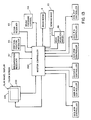
- the machine 101 is a six-axis machine, each axis having an axis controller like the axis controller labeled 1 in Fig. 12.
- the six-axes controllers are marked 1A, 1B...1F in Fig. 13 and, for present purposes, respectively represent the turret axis or rotational drive (1A), the transverse axis or X-direction drive (1B), the lift axis or Z-direction drive (1C), the rock axis drive (1D), the margin axis drive (1E) and the sole axis drive (1F).
- the label 206B designates the transverse axis or X-direction drive motor. That convention is not followed for other parts in the axis controller 1.
- the master controller 200 orchestrates all the activities of the automatic rougher 101; the controller 200 is further discussed elsewhere herein.
- the air cylinder 15 serves to preload the roughing tool 5 toward the cement margin to apply a determinable and closely-controllable force between the roughing tool 5 and the cement margin 108A during roughing.
- the roughing tool 5 is mounted to move short distances (typically of the order of one-fourth inch) in the Z-direction in Fig. 6 with respect to the cement margin 108A in response to the pre-loading pressure of the air cylinder 15 in Fig. 11 and, more precisely, the brush pressure control designated 15A in Fig. 13.
- the sensing hand 23 in Fig. 15 includes a number of encoders which feed back information -- in the form of electrical signals -- indirectly to the master controller 200.
- the feedback is shown as a direct feedback but, in fact, it passes through other circuit elements as noted herein and as is known to persons in this art.
- an encoder is a displacement indicator used to sense position.
- the finger encoders marked 60 and 61 in Fig. 15, for example, measure and provide feedback informaton with respect to depression of fingers 25A and 25B.
- a sole angle encoder 59 measures and provides feedback information with respect to depression of a finger 25C. Other encoders are discussed elsewhere herein.
- a wrist resolver 69 to give rock angle informaton (i.e., pivoting about the Y-axis in Fig. 6), including path contour.
- Other resolvers include a transverse resolver 62, a sizing resolver 63, a vertical position resolver 65 (i.e., pivot of the arm 23), a lift resolver 66 (i.e., Z-direction movement of the carriage 32), a brush position resolver 67, a sole angle resolver 68 , a rock angle resolver 70, and a turret resolver (not shown) and a margin resolver (not shown). These resolvers are discussed elsewhere.
- the automatic rougher 101 includes the sensor hand or array 23 in Fig. 11, which is described in detail herein and which, among other things, establishes position of the cement margin 108A relative to the roughing tool 5.
- a sole angle slide 29 in Figs. 6 and 11 between the roughing tool 5 and the array 23 permits positioning in the Y-direction in Fig. 6 of the roughing tool relative to the array 23 and it also positions the rougher 5 relative to the cement margin 108A along the Y-axis.
- the sensor hand or array 23, Figs. 3 and 4 and 15, etc. has the two fingers 25A and 25B and the two transducers, 60 and 61, respectively (e.g., encoders), in Fig. 15 that act, in combination, to provide a difference signal effective of relative orthogonality between the roughing tool 5 and the cement margin 108A (i.e., orthogonality between the plane of the roughing wheel and the cement-margin path direction) and an average signal that indicates position of the cement margin 108A toward and away from the roughing tool 5. All the signals are interpreted by the master controller 200 and acted appropriately upon.
- the third finger 25C in Fig. 15 acts in combination with the encoder 59 to measure the crown of the sole of the upper assembly and provides a further feedback signal.
- Fig. 11 includes a roughing motor 8 that drives the roughing wheel 5, the sole angle slide or assembly 29 to move the roughing tool toward and away from the upper assembly 108, as well as longitudinally relative to the two fingers 25A and 25B on the basis of signals received from the third transducer 25C to maintain roughing contact between the roughing tool 5 and the cement margin 108A despite change in crown and other parts of the sole of the upper assembly 108.
- the rougher 101 includes also a margin assembly 31 connected to move the roughing tool 5 and the two fingers 25A and 25B, in combination, relative to the upper assembly 108 (i.e., toward and away from the upper assembly) to maintain proper engagement at the feather line thereof.
- the sensor hand 23 includes rollers 26A and 26B that ride on the cement margin 108A, a pneumatic preloader 21 in Fig. 11 presses the rollers 26A and 26B onto the cement margin 108A to maintain the roller engagement.
- the rotary transducer 69 in Fig. 15 is mechanically interconnected to the rollers., 26A and 26B by the sensor hand 23 to pivot about a longitudinal pivot axis located between the rollers 26A and 26B to provide rock angle feedback signals to permit the maintenance of the roughing tool interface parallel to the cement margin.
- the pneumatic preloader 15, which presses the wheel onto the cement margin is controlled by signals from the pneumatic servo valve 9 to apply a force between about zero and twenty pounds at the brush-margin interface.
- Control signals to the pneumatic servo valve 9 come from the master controller 200; the servo pressure regulator of the rougher 101 has about a three-millisecond response time and can maintain the needed force between the roughing tool 5 and the cement margin 108A to a tolerance or resolution of about one-half pound and in a range less than a pound to about twenty pounds.
- the various structures to achieve the needed actions are now taken up; mostly with reference to Figs. 3-15.
- Fig. 3 shows many of the structures discussed above, including the pneumatic servo valve 9, the brush 5, the rollers 26A and 26B and so forth; it (and Figs. 4-15) also places these and other structures in positional context, as now discussed.
- the principal function of the machine 101 is to receive the upper assembly 108; rough the cement margin thereof; and send the duly-roughed upper assembly 108 to another machine to perform an operation thereon.
- information is gathered that guides and determines further operations on the upper assembly 108: e.g., bottom cementing by the machine 103.
- a transverse-drive servomotor 206B drives a transverse lead screw 34 in Fig. 7 through pulleys (as shown) to achieve plus-minus X-direction movement of the upper assembly 108 in Fig. 6.
- the resolver 62 gives position information. Transverse movement is effected by transverse swing arms 6A and 6B in Fig. 8 which alone would move the upper assembly 108 along an arcuate rocking path, but, in the present system, the rocking- arcuate effect is overcome by translational motion in the Z-direction in Fig. 6, whereby the cement margin 108A is moved toward and away from the roughing tool 5.
- the rock carriage 27 which supports the heel post 4, toe rest 3, and so forth, in Fig. 7 is, in turn, supported by the lift carriage 32.
- the lift carriage 32 is supported by lift guide rails 33 upon which ride rollers 35A and 35B to permit the Z-direction movement discussed above.
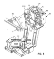
- Z-direction movement up and down of the lift carriage 32 is driven by a lift servomotor 206C in Fig. 9 through a gear reducer and belt drive to a lead screw 41.
- the resolver 66 provides Z-direction position information as feedback from the arm 23 to the controller 200. All the structures discussed in this paragraph are part of the turret 110.
- Fig. 6 the wire wheel 5 is driven by the roughing motor 8 in Fig. 11 through a shaft 20 in Fig. 6.
- the shaft 20 drives a sprocket 40 in Fig. 4 which drives a belt 42 which drives the wheel 5.
- the label 20A in Fig. 4 designates a flexible shaft between the motor 8 and the shaft 20. Particles from the roughed surface are exhausted by a chute 45.
- the wire wheel 5 pivots through the angle 17 about the shaft 20 and the pivoting movement is noted by the resolver 67. It will be appreciated that the scheme just described provides a wheel drive with very low inertia with reference to small movement (about one-fourth inch) toward and away from the cement margin.
- the mass of the motor 8 is isolated from the wire wheel 5.
- the wire wheel 5 is held in contact with the cement margin 108A by the brush load air cylinder 15 that receives control signals from the pneumatic servo valve 9, as above noted; the load beam sensor 19 provides electrical control signals to the valve 9. Movement of the wheel 5 toward and away from the upper assembly is effected by the sole angle slide 29 in Figs. 6 and 11, which is driven by a sole angle screw through a pulley 29A which is driven by a pulley 29B, driven by a sole angle motor. The slide rides on shafts 10A and 10B. An air cylinder 50 provides force to maintain the rollers 26A and 26B on the cement margin.
- the margin slide 31 in Fig. 6 rides on shafts 12A and 12B driven by a pulley 31A which drives a lead screw; the pulley 31A is a belt driven by a pulley 310 which is attached to a margin drive motor.
- a pulley 31C is connected to a drive margin resolver (like the resolver 68).
- the resolvers herein as will be appreciated, give feedback position information to the controller 200 so that the controller is aware at all times of the position of the various parts of the automatic rougher 101.
- the label 110 in Fig. 7, as above indicated, designates a turret mechanism (of which the attachment mechanism 2 is a part) that receives the upper assembly 108 in Fig. 6 and is operable to secure the same relative to the automatic rougher.
- the turret 110 is adapted to apply rocking motion, translational motions and rotational motion to the upper assembly 108 and hence to the cement margin 108A relative to the roughing tool 5, as well as translational motion of the cement margin toward and away from sensor array 23 and hence to the roughing tool to present a uniform area of contact (see the Becka et al patent) at the interface between the roughing tool and the cement margin as well as a controllable rate of removal of the material from the cement margin by the roughing tool.
- Rotation and indexing of the mechanism 110 in Fig. 7 is accomplished with apparatus similar to that disclosed in the Becka et al patent and described in detail there.
- the drive mechanism is marked 113 and it consists of a servomotor (i.e., the servomotor 206A) and gearbox 111 and control device 112 which receives control signals from the controller 200.
- Rotary mechanical forces at 114 are delivered to the turret mechanism 110 much the way it is done in the Becka et al patent.
- the turret mechanism 110 in Fig. 7 includes a scheme to establish size of the upper assembly 108. Essentially what is done here is to provide a measure of length of the upper assembly 108 between the heel post 4 and toe rest 3.
- the elements to accomplish this purpose include a toe switch 54 and a flap switch 56 in Fig. 7 in combination with a sizing screw 52 and the sizing resolver 63. Sizing mechanisms are known in this industry.
- a most important aspect of this invention is that, when the cement margin 108A is being roughed, the various resolvers described above send feedback signals to the controller 200 (similar signals are fedback to the controller 200 by the command sequencer 201 discussed later). These feedback signals include information about the closed-loop path of the cement margin.
- the roughing data which in the automatic rougher 101 is typically with respect to the outline, in plan form, of the roughing path 108A, is saved and is used by the third machine 103 simultaneously or later, as before noted.
- Fig. 12 shows the elements of a single axis controller 1 of the six-axis machine 101 (or the machine 103).
- Each of the six-axes contains the elements shown in Fig. 12, the axes controllers being marked axis 1A...1F in Fig. 13.
- the six axes (1A...1F) can be identified respectively as the turret (i.e., yaw) drive, the transverse or Y-direction drive, the turret lift or Z-direction drive, the rock angle drive, the margin drive and the sole angle drive in Fig. 13.
- Each of the six-axes controllers 1A...1F is identical to the typical controller marked 1 in Fig. 12 which includes the command sequencer 201, a summer 202, a digital-integral-differentiator 204, an encoder feedback 203, a motor amplifier resolver 205, a drive motor 206, a gear train 211 (e.g., a gear train drive G1), a final output shaft drive 210 (that is, a final output drive G2).
- the label 209 (G3) represents a gear reducer; 208 is a resolver; 207 is an encoder.
- the labels 212, 213, 214 and 215 and 216 represent electrical signals and the labels 217, 218, 219 and 220 represent mechanical signals.
- the brush pressure control 15A can be considered to include the pneumatic valve 9 and the air cylinder 15 in Fig. 11, plus any other local machine elements (e.g., the load beam sensor 19) needed to maintain very precise control of force between the brush 5 and the cement margin at the region contact therebetween.
- the upper assembly 108 in Fig. 14 is shown.
- the rectangular areas at the bottom of the touch screen: "open,” margin,” and so forth are also on the display 221 and serve as instructions to the master controller 200, implemented by an operator pressing with his finger onto the touch screen.
- the motor 206 in Fig. 12, as defined, may be any one of the motors in the axis controllers 1A...in Fig. 13, including the lift servomotor marked 206C in Fig. 9.
- the servomotor 206C serves to raise and lower the carriage 33 in Fig. 9, which raises and lowers (i.e., Z-direction movement) the positioning mechanism 2 that includes the heel post 4 and toe rest 3, and hence the last.
- the arm 23 is typically kept about level -- but it can be kept at any other predetermined orientation, level being convenient.
- the up-down movement of the carriage 32 achieves a number of desired results: it accommodates undulations in the upper assembly 108 in response to feed back signals from the sensor hand array 23; and it compensates for Z-direction changes by virtue of angular rocking movements about the axis 30, again in response to signals from the array 23.
- the up-down movements can also be accomplished in response to input signals to the machine 101 through the touch screen 230, as before noted, upon touch inputs by an operator, it being noted that touch screens per se are known.
- the label 30 in Fig. 8 designates a cylindrical opening that receives the shaft, also designated 30, the two acting as the pivot 30.
- the rocking motor 206D in Fig. 8 drives a rock lead screw 12 that effects rocking of the upper assembly 108.
- the rock assembly 27 pivots at 30 but derives mechanical stability from an arcuate member 13 in Fig. 8, which is structurally rigidly mechanically connected to the assembly 27 and which rolls in an arcuate path on rollers 14A and 14B in Fig. 8, connected to the lift structure 32.
- the last pin 4 in Fig. 8 and other related parts are subjected to rocking movement and vertical movement. These movements, as are the other movements herein, are effected and monitored in the context of respective axis controllers, as represented at 1 in Fig. 12.
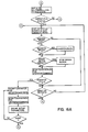
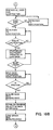
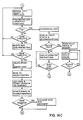
- the flow charts shown in Figs. 16A, 16B and 16C are self explanatory to persons in the art. They tell programmers the many instructions needed by the master controller 200 to accomplish the functions above noted.
- the master controller 200 in actual apparatus is a computer that drives the dedicated microprocessors that include the elements 201, 202, 203 and 204 to provide real time data for operations of the machine 101.
- the wheel drive motor 8 is isolated by the flexible coupling 20A from the arm 10 that supports the wheel 5 and is not affected by pivoting of the arm 10 about the shaft 20, thereby presenting relatively small moving mass by the brush 5 and related parts.
- the brush pressure control and related parts have very fast response times, as noted.
- the digital real time calculations permit the needed real time correction signals to permit the active elements to track the cement margin as it moves relative to the wheel 5 on the basis of feedback signals from the encoders and resolvers.
- An encoder as is known, is an optical position measuring transducer --linear or angular -- relative to a known position; a resolver is an electromagnetic device that measures an error signal that indicates position).
- the controller 200 provides to the axis controllers 1A... signals to achieve positioning of the various parts of the machine 101 to achieve a desired rate of removal of material from the cement margin, but, also, the various transducers send back signals that are used to change that positioning, to the extent change is required. These and further aspects of the machine 101 enable close control of material removal. Typically the Z-direction (up/down) position of the area being roughed is maintained substantially constant throughout a roughing cycle.
- the labels 207B and 207D are for encoders.
- the invention herein before described includes a method to effect integrated operations on a footwear upper assembly in a system that includes a first machine, a second machine and a third machine, which first machine is an automatic rougher, which second machine is a transfer machine and which third machine is adapted to perform further operations on the footwear upper assembly, said footwear upper assembly comprising a last, a footwear upper disposed on the last and an insole on the last bottom, said footwear upper assembly having a cement margin to-be-roughed, said method comprising: effecting roughing of the footwear upper assembly by a roughing tool operable to remove material from the cement margin along a closed-loop path to provide a cementing surface therealong; attaching and positioning the footwear upper assembly by a mechanism that is operable to secure the footwear upper assembly relative to the roughing tool and apply motion of the cement margin relative to the roughing tool, which motion includes translational movement of the footwear upper assembly toward and away from the roughing tool in the course of roughing to present the footwear upper assembly to the roughing tool; sensing the position of
Landscapes
- Footwear And Its Accessory, Manufacturing Method And Apparatuses (AREA)
- Finish Polishing, Edge Sharpening, And Grinding By Specific Grinding Devices (AREA)
Applications Claiming Priority (2)
| Application Number | Priority Date | Filing Date | Title |
|---|---|---|---|
| US179172 | 1988-04-08 | ||
| US07/179,172 US4866802A (en) | 1988-04-08 | 1988-04-08 | Roughing machine for footware upper assemblies and a system that includes the roughing machine but typically includes as well other machines ahead of and following |
Publications (2)
| Publication Number | Publication Date |
|---|---|
| EP0336632A2 true EP0336632A2 (de) | 1989-10-11 |
| EP0336632A3 EP0336632A3 (de) | 1991-04-17 |
Family
ID=22655517
Family Applications (1)
| Application Number | Title | Priority Date | Filing Date |
|---|---|---|---|
| EP19890303087 Withdrawn EP0336632A3 (de) | 1988-04-08 | 1989-03-29 | Aufrauhmaschine für Schuhoberteileinheiten und Aufrauhmaschine umfassendes System |
Country Status (6)
| Country | Link |
|---|---|
| US (1) | US4866802A (de) |
| EP (1) | EP0336632A3 (de) |
| JP (1) | JPH0221802A (de) |
| BR (1) | BR8901601A (de) |
| CA (1) | CA1329969C (de) |
| RU (1) | RU1814532C (de) |
Cited By (6)
| Publication number | Priority date | Publication date | Assignee | Title |
|---|---|---|---|---|
| US5101528A (en) * | 1989-06-15 | 1992-04-07 | British United Shoe Machinery Ltd. | Machine for roughing side walls portions of a shoe |
| EP0591596A1 (de) * | 1992-03-27 | 1994-04-13 | COMELZ S.p.A. | Automatisches Schuhherstellungssystem, insbesondere zur Aufrauhung und Verklebung von Schuhschäften |
| EP0655207A1 (de) * | 1993-10-29 | 1995-05-31 | OFFICINA MECCANICA B.D.F. s.r.l. | Automat für kontrollierte Aufrauhung der Kante eines Schuhoberteils |
| WO1996019129A1 (en) * | 1994-12-22 | 1996-06-27 | British United Shoe Machinery Limited | Machine for performing a roughing operation progressively along marginal portions of a shoe bottom |
| EP1285596A1 (de) * | 2001-08-16 | 2003-02-26 | Officina Meccanica B.D.F. S.P.A. | Verfahren zur Feststellung und Kompensation der seitlichen Drehung von einem Schuhleisten im Vergleich mit einer vorbestimmten Position in einer automatischen Schuhbearbeitungsvorrichtung |
| GB2381331A (en) * | 2001-08-04 | 2003-04-30 | Korea Advanced Inst Sci & Tech | A system for generating a cementing trajectory for a shoe |
Families Citing this family (11)
| Publication number | Priority date | Publication date | Assignee | Title |
|---|---|---|---|---|
| GB8901557D0 (en) * | 1988-07-20 | 1989-03-15 | British United Shoe Machinery | Operating on side wall portions of a lasted shoe upper |
| US5807449A (en) * | 1997-01-08 | 1998-09-15 | Hooker; Jeffrey A. | Workpiece treating apparatus and method of treating same |
| US6259519B1 (en) | 1999-08-31 | 2001-07-10 | Intelligent Machine Concepts, L.L.C. | Method of determining the planar inclination of a surface |
| US6327520B1 (en) | 1999-08-31 | 2001-12-04 | Intelligent Machine Concepts, L.L.C. | Planar normality sensor |
| US8755925B2 (en) * | 2011-11-18 | 2014-06-17 | Nike, Inc. | Automated identification and assembly of shoe parts |
| US10552551B2 (en) | 2011-11-18 | 2020-02-04 | Nike, Inc. | Generation of tool paths for shore assembly |
| US8958901B2 (en) | 2011-11-18 | 2015-02-17 | Nike, Inc. | Automated manufacturing of shoe parts |
| US8849620B2 (en) | 2011-11-18 | 2014-09-30 | Nike, Inc. | Automated 3-D modeling of shoe parts |
| US9451810B2 (en) | 2011-11-18 | 2016-09-27 | Nike, Inc. | Automated identification of shoe parts |
| EP3302152B1 (de) * | 2015-06-03 | 2019-12-04 | To-a-T IP B.V. | Verfahren und vorrichtung zur herstellung von einlegesohlen |
| US20170172259A1 (en) * | 2015-12-17 | 2017-06-22 | Pou Chen Corporation | Multi-Axis Automatic Shoe Sole Processing Apparatus and Method of the Same |
Citations (3)
| Publication number | Priority date | Publication date | Assignee | Title |
|---|---|---|---|---|
| EP0150116A2 (de) * | 1984-01-20 | 1985-07-31 | International Shoe Machine Corporation | Automatische Maschine zum Aufrauhen des Schaftkleberandes einer Schuheinheit |
| GB2173989A (en) * | 1985-04-09 | 1986-10-29 | Tovarne Strojarskej Tech | Device for controlling the position of a partly finished shoe |
| EP0250214A2 (de) * | 1986-06-20 | 1987-12-23 | International Shoe Machine Corporation | Automatische Maschine zum Aufrauhen des Schaftkleberandes einer Schuheinheit |
Family Cites Families (26)
| Publication number | Priority date | Publication date | Assignee | Title |
|---|---|---|---|---|
| GB1234404A (de) * | 1967-08-12 | 1971-06-03 | ||
| GB1285559A (en) * | 1968-10-10 | 1972-08-16 | British United Shoe Machinery | Improvements in or relating to apparatus suitable for use in the manufacture of shoes |
| US3559428A (en) * | 1969-06-02 | 1971-02-02 | Usm Corp | Shoe bottom roughing machines |
| US3704604A (en) * | 1970-06-27 | 1972-12-05 | Usm Corp | Automatic bottom roughing machine |
| US3645118A (en) * | 1970-10-23 | 1972-02-29 | Usm Corp | Shoe bottom roughing machines |
| US3843985A (en) * | 1973-08-30 | 1974-10-29 | Int Shoe Machine Corp | Machine for roughing the margin of an upper of a shoe assembly |
| US3932907A (en) * | 1975-02-03 | 1976-01-20 | International Shoe Machine Corporation | Roughing machine |
| US4020660A (en) * | 1975-08-28 | 1977-05-03 | International Shoe Machine Corporation | Roughing machine having tool position adjusting mechanism |
| US3975932A (en) * | 1975-10-09 | 1976-08-24 | International Shoe Machine Corporation | Roughing machine having tool position adjusting mechanism |
| CA1037211A (en) * | 1975-11-20 | 1978-08-29 | Usm Corporation | Shoe machine shoe size and side sensing arrangement |
| US3992743A (en) * | 1976-04-12 | 1976-11-23 | International Shoe Machine Corporation | Roughing machine with damper mechanism |
| GB1585961A (en) * | 1976-08-24 | 1981-03-11 | British United Shoe Machinery | Apparatus suitable for use in the manufacture of shoes |
| US4126021A (en) * | 1976-08-24 | 1978-11-21 | Usm Corporation | Dust extraction arrangement for an automatic roughing machine |
| DE2650079C3 (de) * | 1976-10-30 | 1980-06-26 | Internationale Schuh-Maschinen Co Gmbh, 6780 Pirmasens | Vorrichtung zum Aufrauhen des Schaftzwickrandes einer Schuheinheit |
| DE2715064C2 (de) * | 1977-04-04 | 1984-12-13 | Fortuna-Werke Maschinenfabrik Gmbh, 7000 Stuttgart | Vorrichtung zum Fertigen von Schuhen |
| US4134278A (en) * | 1977-11-25 | 1979-01-16 | International Shoe Machine Corporation | Machine for performing an operation along a non-rectilinear workpiece periphery |
| US4167103A (en) * | 1978-07-21 | 1979-09-11 | International Shoe Machine Corporation | Machine for roughing the margin of an upper of a shoe assembly |
| DE3163180D1 (en) * | 1980-06-10 | 1984-05-24 | British United Shoe Machinery | Machine for performing a roughing operation progressively along marginal portions of shoe bottoms |
| GB2077090B (en) * | 1980-06-10 | 1983-11-23 | British United Shoe Machinery | Shoe support for a machine for use in the manufacture of shoes |
| US4331011A (en) * | 1980-06-10 | 1982-05-25 | Usm Corporation | Automatic roughing machine |
| US4756038A (en) * | 1980-06-20 | 1988-07-12 | International Shoe Machine Corporation | Machine for automatically roughing the cement margin of a footwear upper assembly |
| US4389861A (en) * | 1981-06-08 | 1983-06-28 | Usm Corporation | Machine adapted for use in the manufacture of shoes |
| DE3276350D1 (en) * | 1981-11-13 | 1987-06-25 | British United Shoe Machinery | Machine suitable for operating progressively along marginal portions of shoe bottoms |
| IT1155202B (it) * | 1982-08-30 | 1987-01-21 | Cerim Spa | Macchina per la cardatura automatica di tomaie per calzature |
| CS249085B1 (en) * | 1985-03-25 | 1987-03-12 | Antonin Petrzelka | Device for lasting margin's lacerating |
| US4769866A (en) * | 1986-11-21 | 1988-09-13 | International Shoe Machine Corporation | Multi-station system to act upon footwear upper assemblies with transfer between stations thereof |
-
1988
- 1988-04-08 US US07/179,172 patent/US4866802A/en not_active Expired - Fee Related
-
1989
- 1989-01-09 RU SU894613223A patent/RU1814532C/ru active
- 1989-03-09 CA CA000593209A patent/CA1329969C/en not_active Expired - Fee Related
- 1989-03-29 EP EP19890303087 patent/EP0336632A3/de not_active Withdrawn
- 1989-04-05 BR BR898901601A patent/BR8901601A/pt unknown
- 1989-04-05 JP JP1084937A patent/JPH0221802A/ja active Pending
Patent Citations (3)
| Publication number | Priority date | Publication date | Assignee | Title |
|---|---|---|---|---|
| EP0150116A2 (de) * | 1984-01-20 | 1985-07-31 | International Shoe Machine Corporation | Automatische Maschine zum Aufrauhen des Schaftkleberandes einer Schuheinheit |
| GB2173989A (en) * | 1985-04-09 | 1986-10-29 | Tovarne Strojarskej Tech | Device for controlling the position of a partly finished shoe |
| EP0250214A2 (de) * | 1986-06-20 | 1987-12-23 | International Shoe Machine Corporation | Automatische Maschine zum Aufrauhen des Schaftkleberandes einer Schuheinheit |
Cited By (8)
| Publication number | Priority date | Publication date | Assignee | Title |
|---|---|---|---|---|
| US5101528A (en) * | 1989-06-15 | 1992-04-07 | British United Shoe Machinery Ltd. | Machine for roughing side walls portions of a shoe |
| EP0591596A1 (de) * | 1992-03-27 | 1994-04-13 | COMELZ S.p.A. | Automatisches Schuhherstellungssystem, insbesondere zur Aufrauhung und Verklebung von Schuhschäften |
| EP0655207A1 (de) * | 1993-10-29 | 1995-05-31 | OFFICINA MECCANICA B.D.F. s.r.l. | Automat für kontrollierte Aufrauhung der Kante eines Schuhoberteils |
| WO1996019129A1 (en) * | 1994-12-22 | 1996-06-27 | British United Shoe Machinery Limited | Machine for performing a roughing operation progressively along marginal portions of a shoe bottom |
| GB2381331A (en) * | 2001-08-04 | 2003-04-30 | Korea Advanced Inst Sci & Tech | A system for generating a cementing trajectory for a shoe |
| KR100431645B1 (ko) * | 2001-08-04 | 2004-05-17 | 한국과학기술원 | 신발 바닥의 이상적인 풀칠경로와 실제 풀칠 작업경로를생성하는 방법 |
| GB2381331B (en) * | 2001-08-04 | 2005-10-05 | Korea Advanced Inst Sci & Tech | Method for generating an ideal cementing trajectory and an actual cementing operation trajectory |
| EP1285596A1 (de) * | 2001-08-16 | 2003-02-26 | Officina Meccanica B.D.F. S.P.A. | Verfahren zur Feststellung und Kompensation der seitlichen Drehung von einem Schuhleisten im Vergleich mit einer vorbestimmten Position in einer automatischen Schuhbearbeitungsvorrichtung |
Also Published As
| Publication number | Publication date |
|---|---|
| JPH0221802A (ja) | 1990-01-24 |
| US4866802A (en) | 1989-09-19 |
| EP0336632A3 (de) | 1991-04-17 |
| BR8901601A (pt) | 1989-11-21 |
| CA1329969C (en) | 1994-06-07 |
| RU1814532C (ru) | 1993-05-07 |
Similar Documents
| Publication | Publication Date | Title |
|---|---|---|
| US4866802A (en) | Roughing machine for footware upper assemblies and a system that includes the roughing machine but typically includes as well other machines ahead of and following | |
| CA1237271A (en) | Apparatus for assembling door for vehicle | |
| US5968297A (en) | Workpiece treating apparatus and method of treating same | |
| US5059090A (en) | Two-dimensional positioning apparatus | |
| JPS6365624B2 (de) | ||
| ES8400042A1 (es) | Metodo para el mando automatico del recorrido de una biseladora de cantos omnidireccional para cristales y aparato para ponerlo en practica. | |
| US4886529A (en) | Polishing robot and polishing method using the same | |
| US4945593A (en) | Automatic determination of coordinates of the operating path of an adhesive-applying nozzle in an adhesive applicator for a shoe machine | |
| JPH0722523B2 (ja) | 靴の製造に際して靴の縁部の連続加工を行う機械 | |
| CA1213108A (en) | Machine for automatically roughing the cement margin of a footwear upper assembly | |
| EP0371967B1 (de) | Gerät zum abtasten einer unbearbeiteten linse und eine maschine mit einem solchen gerät | |
| DE4104468C1 (en) | Automatic shoe upper finisher for several work stations - has table with four stations on central column, and conveying turntable, reaching beyond table | |
| JPS6229378B2 (de) | ||
| US4756038A (en) | Machine for automatically roughing the cement margin of a footwear upper assembly | |
| EP0250214A2 (de) | Automatische Maschine zum Aufrauhen des Schaftkleberandes einer Schuheinheit | |
| JPH0446717B2 (de) | ||
| JPH0397405A (ja) | 製靴用糊付機 | |
| US5071297A (en) | Method and copying means for the digital control of a machine tool | |
| JP3623986B2 (ja) | スクリーン印刷機 | |
| US4835995A (en) | Machining device, especially for a robot used for the carding of leather | |
| JP2577092B2 (ja) | 研削加工装置 | |
| JPS60177918A (ja) | スピニングマシンの加工方法 | |
| JPH04111768A (ja) | ロボットの仕上げ加工制御装置 | |
| SU989322A1 (ru) | Двухкоординатное чертежное устройство | |
| JP2810905B2 (ja) | 用紙駆動型自動製図機における用紙検出方法 |
Legal Events
| Date | Code | Title | Description |
|---|---|---|---|
| PUAI | Public reference made under article 153(3) epc to a published international application that has entered the european phase |
Free format text: ORIGINAL CODE: 0009012 |
|
| AK | Designated contracting states |
Kind code of ref document: A2 Designated state(s): DE FR GB IT |
|
| PUAL | Search report despatched |
Free format text: ORIGINAL CODE: 0009013 |
|
| STAA | Information on the status of an ep patent application or granted ep patent |
Free format text: STATUS: THE APPLICATION HAS BEEN WITHDRAWN |
|
| AK | Designated contracting states |
Kind code of ref document: A3 Designated state(s): DE FR GB IT |
|
| 18W | Application withdrawn |
Withdrawal date: 19910326 |