EP0336479A2 - Spectromètre à résonance magnétique nucléaire - Google Patents
Spectromètre à résonance magnétique nucléaire Download PDFInfo
- Publication number
- EP0336479A2 EP0336479A2 EP89200757A EP89200757A EP0336479A2 EP 0336479 A2 EP0336479 A2 EP 0336479A2 EP 89200757 A EP89200757 A EP 89200757A EP 89200757 A EP89200757 A EP 89200757A EP 0336479 A2 EP0336479 A2 EP 0336479A2
- Authority
- EP
- European Patent Office
- Prior art keywords
- frequency
- signal
- analog
- circuit
- magnetic resonance
- Prior art date
- Legal status (The legal status is an assumption and is not a legal conclusion. Google has not performed a legal analysis and makes no representation as to the accuracy of the status listed.)
- Granted
Links
Images

Classifications
-
- G—PHYSICS
- G01—MEASURING; TESTING
- G01R—MEASURING ELECTRIC VARIABLES; MEASURING MAGNETIC VARIABLES
- G01R33/00—Arrangements or instruments for measuring magnetic variables
- G01R33/20—Arrangements or instruments for measuring magnetic variables involving magnetic resonance
- G01R33/28—Details of apparatus provided for in groups G01R33/44 - G01R33/64
- G01R33/32—Excitation or detection systems, e.g. using radio frequency signals
- G01R33/36—Electrical details, e.g. matching or coupling of the coil to the receiver
- G01R33/3621—NMR receivers or demodulators, e.g. preamplifiers, means for frequency modulation of the MR signal using a digital down converter, means for analog to digital conversion [ADC] or for filtering or processing of the MR signal such as bandpass filtering, resampling, decimation or interpolation
Definitions
- the invention relates to a nuclear magnetic resonance spectrometer in which an analog-digital converter in the receiving branch converts the nuclear magnetic resonance signals or a nuclear magnetic resonance signal transposed into a lower frequency range into a digital signal and a Fourier transformation circuit is arranged in a signal path behind the analog-digital converter is.
- a nuclear magnetic resonance spectrometer of this type is described in DE-OS 36 04 281.
- the nuclear magnetic resonance signal is converted into the baseband and only then converted into a sequence of digital data words using an analog-digital converter. Because of the conversion to the baseband, quadrature demodulation is required, the nuclear magnetic resonance signal being mixed with an oscillation at a Lamor frequency, which is supplied to the two mixing stages with a phase shift of 90 °.
- the two mixing stages of the known spectrometer must be constructed exactly symmetrically, and the phase shift between the two vibrations must be exactly 90 °.
- the fulfillment of this requirement with an analog mixing stage is relatively complex.
- Another disadvantage is that the lowest useful frequency in the baseband is so low that a DC voltage amplifier must be used to amplify the output signal of the mixer stages. Shifting the operating point of this amplifier results in a disturbing drift, which leads to reconstruction errors in the further processing of the signal.
- the low-frequency 1 / f noise (often also referred to as sparkling noise) and harmonics of the mains frequency have a particularly disruptive effect in the baseband.
- the object of the invention is to design a spectrometer of the type mentioned in such a way that the complex analog components can be dispensed with and the reconstruction is not adversely affected by drift effects.
- At least one circuit is arranged in the signal path between the analog-to-digital converter and the Fourier transformation circuit, which consists of a digital filter and a sampling frequency reducing circuit, the output signals of which are reduced by an integer factor compared to their input signals Have sampling frequency and that the reduced sampling frequency is a non-integer factor smaller than the frequency of the signal at the output of the digital filter.
- the signal processing is carried out essentially digitally. Drift effects are irrelevant.
- there is currently no Fourier transformation circuit which would allow an analog signal to be subjected to a Fourier transformation in real time in the frequency range (a few MHz) that results from nuclear spin examinations. At present, this is only possible with economically justifiable expenditure up to frequencies of a few 100 KHz.
- a sampling frequency reducing circuit which reduces the sampling frequency to such an extent that the Fourier transform circuit can process it.
- the sampling frequency at which the nuclear magnetic resonance signal is finally fed to the Fourier transform circuit is essential is lower than the frequency of the signal itself.
- the sampling frequency is selected at least twice as high as the signal frequency, in order to avoid effects of spectral convolution (aliasing) which cause signal distortion.
- the invention takes advantage of the fact that the center frequency of the nuclear magnetic resonance signals is known and that these nuclear magnetic resonance signals have a narrow bandwidth compared to this center frequency.
- the sampling frequency can therefore always be selected in relation to the signal frequency in such a way that the useful signal can be transposed by under-sampling (undersampling) into a frequency range outside the baseband and within a periodic grid defined by half the sampling frequency.
- the upstream digital filter ensures that no interference signals from another frequency range can get into this area by convolution.
- the reduced sampling frequency is smaller than the frequency of the signal at the output of the digital filter by a non-integer factor, it can always be achieved that the useful signal band does not fall into the baseband, i.e. is folded into a frequency range around zero frequency.
- a spectrometer does not - like the known spectrometer with a quadrature demodulator - need two signal paths in which the nuclear magnetic resonance signal is processed before the Fourier transformation, but only one.
- the factor by which the sampling frequency is reduced cannot be chosen to be as large as desired, because this results in requirements for the digital filter that can hardly be met.
- a possibility, but still a big enough one To achieve a reduction in the sampling frequency is to connect two of the circuits consisting of the digital filter and the sampling frequency reduction circuit in the signal path.
- Another possibility is that the quotient of the frequency of the analog input signal and the sampling frequency is greater than 0.5 and not an integer.
- the sampling frequency of the analog-digital converter is chosen to be so low that undersampling and the associated aliasing effects result, by means of which the analog input signal is digitally transposed into a lower frequency range.
- the fact that the quotient of the signal frequency and the sampling frequency is not an integer prevents the signal from reaching the baseband.
- Fig. 1, 1 denotes a device that generates a homogeneous and stationary magnetic field of, for example, 0.21 T running perpendicular to the plane of the drawing in an examination area 2 and that also generates magnetic gradient fields if required, ie magnetic fields that run in the same direction like the homogeneous, stationary magnetic field, the strength of which changes linearly in the direction of the magnetic field or in a direction perpendicular thereto.
- the device 1 is coupled to a generator 3, which generates the stationary magnetic field, and to a generator 4, which supplies the currents for the various magnetic gradient fields.
- a high-frequency coil 5 which generates a high-frequency magnetic field that is perpendicular to the stationary magnetic field in transmission mode and records the nuclear magnetic resonance signals that arise in the examination area in reception mode and that is connected to the output of a spectrometer 6.
- the spectrometer delivers the radio-frequency energy for the radio-frequency coil 5 in transmission mode and processes the nuclear magnetic resonance signals induced in this coil in reception mode.
- the generators 3 and 4 and the spectrometer 6 are controlled by a digital central unit 7, which contains a control part 71 for this purpose.
- the digital central unit comprises a processing part 72, which processes the data supplied by the spectrometer 6 and reconstructs the nuclear magnetization distribution in the examination area 2 therefrom. This processing includes also a Fourier transformation that takes place in real time.
- the signal received by the high-frequency coil 5 from the examination area is fed to a preamplifier 61.
- the mean value of the frequency of the nuclear magnetic resonance signal is approximately 9 MHz.
- the bandwidth depends on the size of the gradient of the magnetic gradient field that is switched on during the acquisition of the nuclear magnetic resonance signal and on that Size of the examination area. In general, the bandwidth is not larger than 60 KHz.
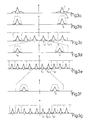
- the spectrum at the output a of the preamplifier 61 is shown in FIG. 3a, in which the schematically indicated spectrum of the nuclear magnetic resonance signal is denoted by S and the much wider noise spectrum by N.
- the output signal of the preamplifier is fed to an analog-to-digital converter 63 via an analog bandpass 62 with a center frequency of 9 MHz.
- the spectrum of the signal at the output b of the analog bandpass 62 shown in FIG. 3b essentially corresponds to the spectrum shown in FIG. 3a, with only the noise band due to the effect of the bandpass, the transfer function of which is schematically indicated by F in FIG. 3b , has been cut.
- the analog-digital converter 63 converts the analog input signal into a sequence of digital data words with a length of 12 bits; With the usual requirements for signal dynamics, a word length of 10 bits could also be sufficient.
- the gain of the preamplifier 61 must be selected so that the noise component of the nuclear magnetic resonance signal is greater than a quantization stage of the converter 63.
- the sampling frequency f a with which the analog nuclear magnetic resonance signal is sampled, is 7.2 MHz. This scanning results in a conversion of the signal frequency f s from a value of 9 MHz to a value f s1 of 1.8 MHz, which is in a frequency range from -f a2 to + f a2 (3.6 MHz) repeats periodically with the period f a .
- the bandpass filter 62 In order to prevent interference voltages from outside the useful frequency range from being converted to the frequency f s1 and in the vicinity thereof, the bandpass filter 62 must be designed so that all frequency components at a distance of more than 1.8 MHz from the frequency f s are as large as possible be suppressed.
- 3c shows the spectrum at the output of the analog-digital converter 63.
- the frequency f s1 1.8 MHz results from the amount of the difference f s - f a .
- the output signal of the analog-to-digital converter 63 is fed to a digital filter 64 with a bandpass characteristic, which operates at the same sampling frequency as the analog-to-digital converter 63.
- the center frequency of this bandpass is at the frequency f s1 (1.8 MHz), and the transfer function of this filter is selected so that the noise beyond the useful frequency band is suppressed in order to prevent these noise components from being folded into the signal frequency range by the subsequent processing of the signal.
- the spectrum at the output d of this filter is shown in FIG. 3d (on a different frequency scale than FIGS. 3a to 3c).
- the output signal of the digital filter is fed to a first sampling frequency reducing circuit 65.
- the task of this circuit is to feed only every pth data word for further processing, p being an integer factor, which in this case is 5.
- p being an integer factor, which in this case is 5.
- Such a sampling and reducing circuit can be implemented in various ways. It can comprise, for example, a gate circuit and a counter which counts pulses with the sampling frequency f a and is reset after every fifth pulse, and thereby the gate circuit opens so that the data word present at that moment can pass. It is also possible to supply the clock frequency to the gate via a frequency divider.
- Fig. 3e shows the spectrum in the output of the circuit 65.
- the new sampling frequency f a1 1.44 MHz results, which has the consequence that the spectrum with the periodicity of f a1 repeated.
- the signal frequency is also reduced by a factor of 5, so that the signal frequency f s2 at the output of the circuit is 65 360 KHz (f s1 / p).
- the reduction in the sampling frequency corresponds to a renewed subsampling - this time in the digital range - and has the consequence that frequencies which were previously far from the useful frequency can be folded into the useful frequency range.
- the bandpass 64 must suppress all signals as far as possible at a bandwidth of 720 kHz (ie in each case at a distance of 360 kHz from f s1 ). However, it would not hurt if the suppression only succeeded at frequencies that were slightly further outside. Components from the band from 0 to f a (FIG. 3c) would then already be folded into the band from 0 to f a1 , but the folded components would lie on the edges of the range 0 to f a1 , where there is also only noise , but not the useful signal.
- the frequencies f s1 and f s2 are always exactly in the middle of the range from 0 to f a1 ⁇ 2 and from 0 to f a11 ⁇ 2 . If the signal frequencies were shifted to one side, the demands on the filters 62 and 64 would increase.
- n 1.
- the output signal of the sampling reduction circuit 64 is fed via a further digital filter 66 with a bandpass characteristic to a further sampling and reduction circuit 67.
- the sampling frequency of the Filters 66 is f a1 (1.44 MHz).
- the center frequency of the filter is 360 KHz and its bandwidth is approximately 72 KHz. At the output of the filter, this results in the frequency spectrum of FIG. 3f, which is again shown on an enlarged scale compared to FIGS. 3d and e.
- the sampling frequency reducing circuit 67 reduces the data stream once again to a fifth, ie of the 1.44 million data words which occur at the input of the circuit 77 per second, only every fifth data word is processed, ie 288,000 data words per second.
- this value again fulfills the condition according to equation 1 if f s is replaced by f s2 and f a by f a2 .
- the signal frequency f s2 is also reduced to a fifth, ie from 360 kHz to 72 kHz.
- the resulting spectrum at the output of each circuit 67 is shown in Fig. 3g.
- circuit 67 The output of circuit 67 is fed to a Fourier transform circuit 720, which is part of processing circuit 72.
- the clock frequency for the input signal is identical to the frequency f a2 , so that during the sampling interval lasting between 2 and 30 ms, during which the nuclear magnetic resonance signal is converted into a sequence of data words, a few thousand data words are processed in the circuit 720, which result therefrom for half the number of discrete frequencies, the spectral components are calculated according to magnitude and phase using a Fourier transformation.
- This circuit can contain a system of several transputers that process the samples simultaneously. The frequency spectrum reconstructed in this way is recorded (cf. Fig. 3g) the entire frequency range from 0 to f a1 ⁇ 2 (144 KHz).
- the useful signal band essential for further processing is much narrower and is, for example, only 20 KHz.
- those of the output signals of the circuit 710 are used for the further processing which correspond to this frequency band, which are assigned frequencies between 62 kHz and 82 kHz in the assumed example.
- a nuclear magnetic resonance spectrometer was described above, in which the nuclear magnetic resonance signals were fed directly to the analog-to-digital converter. However, if these signals have a frequency that is higher than the frequency that can be processed by the analog-digital converter, they must first be transported to a lower frequency range using a mixer before digitization.
Applications Claiming Priority (2)
| Application Number | Priority Date | Filing Date | Title |
|---|---|---|---|
| DE3811066A DE3811066A1 (de) | 1988-03-31 | 1988-03-31 | Kernresonanz-spektrometer |
| DE3811066 | 1988-03-31 |
Publications (3)
| Publication Number | Publication Date |
|---|---|
| EP0336479A2 true EP0336479A2 (fr) | 1989-10-11 |
| EP0336479A3 EP0336479A3 (fr) | 1991-01-02 |
| EP0336479B1 EP0336479B1 (fr) | 1997-01-29 |
Family
ID=6351215
Family Applications (1)
| Application Number | Title | Priority Date | Filing Date |
|---|---|---|---|
| EP89200757A Expired - Lifetime EP0336479B1 (fr) | 1988-03-31 | 1989-03-24 | Spectromètre à résonance magnétique nucléaire |
Country Status (5)
| Country | Link |
|---|---|
| US (1) | US4949040A (fr) |
| EP (1) | EP0336479B1 (fr) |
| JP (1) | JPH0212080A (fr) |
| DE (2) | DE3811066A1 (fr) |
| IL (1) | IL89784A0 (fr) |
Cited By (1)
| Publication number | Priority date | Publication date | Assignee | Title |
|---|---|---|---|---|
| EP0411840A2 (fr) * | 1989-08-04 | 1991-02-06 | General Electric Company | Récepteur de haute fréquence pour un instrument à résonance magnétique nucléaire |
Families Citing this family (13)
| Publication number | Priority date | Publication date | Assignee | Title |
|---|---|---|---|---|
| US5109854A (en) * | 1990-02-23 | 1992-05-05 | Picker International, Inc. | Roll-over aliasing suppression in undersampled images |
| JPH06147116A (ja) * | 1992-11-13 | 1994-05-27 | Toyota Autom Loom Works Ltd | ピストン型圧縮機 |
| US5529068A (en) * | 1994-06-16 | 1996-06-25 | The Regents Of The University Of California | Synchronized digital signal processor for MRI reception |
| US5594341A (en) * | 1994-06-27 | 1997-01-14 | Varian Associates, Inc. | Nuclear magnetic resonance receiver, method and system |
| US5739691A (en) * | 1995-11-28 | 1998-04-14 | The Regents Of The University Of California | Multi-frequency digital low pass filter for magnetic resonance imaging |
| EP1454156A1 (fr) * | 2001-11-26 | 2004-09-08 | Koninklijke Philips Electronics N.V. | Procede d'imagerie par resonance magnetique a bruit acoustique reduit |
| US20090285336A1 (en) * | 2006-06-16 | 2009-11-19 | Michael Anthony Pugel | Wideband Out-Of-Band-Receiver |
| EP2095146A1 (fr) * | 2006-12-19 | 2009-09-02 | Koninklijke Philips Electronics N.V. | Système d'irm avec récepteur numérique direct utilisant le re-échantillonnage |
| CN102103195B (zh) * | 2009-12-18 | 2014-01-15 | 东软飞利浦医疗设备系统有限责任公司 | 一种宽频带数字磁共振射频接收实现装置及方法 |
| JP5686983B2 (ja) * | 2010-03-30 | 2015-03-18 | ジーイー・メディカル・システムズ・グローバル・テクノロジー・カンパニー・エルエルシー | 信号処理装置および磁気共鳴イメージング装置 |
| DE102011086288B4 (de) | 2011-11-14 | 2014-10-09 | Siemens Aktiengesellschaft | Magnetresonanztomographie-System, Empfangsvorrichtung für ein solches System sowie Verfahren zum Gewinnen eines Bildsignals in dem System |
| US9536423B2 (en) * | 2013-03-31 | 2017-01-03 | Case Western Reserve University | Fiber optic telemetry for switched-mode current-source amplifier in magnetic resonance imaging (MRI) |
| FR3034274B1 (fr) * | 2015-03-27 | 2017-03-24 | Stmicroelectronics Rousset | Procede de traitement d'un signal analogique issu d'un canal de transmission, en particulier un signal vehicule par courant porteur en ligne |
Citations (5)
| Publication number | Priority date | Publication date | Assignee | Title |
|---|---|---|---|---|
| EP0132337A2 (fr) * | 1983-07-21 | 1985-01-30 | The Regents Of The University Of California | Appareil et procédé pour réduire les "alias-artefacts" dans les formations d'images en sagittal ou coronal par RMN |
| EP0144026A2 (fr) * | 1983-11-25 | 1985-06-12 | General Electric Company | Appareil et procéde pour la production d'images par résonance magnétique nucléaire avec balayage zoom décentré |
| EP0148362A1 (fr) * | 1983-11-11 | 1985-07-17 | JEOL Ltd. | Méthode pour obtenir un effet pseudo-filtration en procédé d'accumulation et spectroscopie résonance magnétique nucléaire |
| JPS6270741A (ja) * | 1985-09-25 | 1987-04-01 | Hitachi Ltd | 核磁気共鳴イメージング装置 |
| EP0219206A2 (fr) * | 1985-08-16 | 1987-04-22 | Siemens Aktiengesellschaft | Détection sensible à la phase dans des systèmes tomographiques à résonance magnétique nucléaire |
Family Cites Families (4)
| Publication number | Priority date | Publication date | Assignee | Title |
|---|---|---|---|---|
| US32712A (en) * | 1861-07-02 | Shutter and door fastener | ||
| US4567439A (en) * | 1983-09-23 | 1986-01-28 | Texas Instruments Incorporated | Apparatus for measuring the magnitude of a magnetic field |
| US4743851A (en) * | 1985-08-27 | 1988-05-10 | Resonex, Inc. | Apparatus and method for creating non-orthogonal magnetic resonance imaging |
| DE3604281A1 (de) * | 1986-02-12 | 1987-08-13 | Philips Patentverwaltung | Verfahren zur bestimmung der kernmagnetisierungsverteilung in einer schicht eines untersuchungsbereiches und kernspintomograph zur durchfuehrung des verfahrens |
-
1988
- 1988-03-31 DE DE3811066A patent/DE3811066A1/de not_active Withdrawn
-
1989
- 1989-03-20 US US07/325,630 patent/US4949040A/en not_active Expired - Fee Related
- 1989-03-24 DE DE58909771T patent/DE58909771D1/de not_active Expired - Fee Related
- 1989-03-24 EP EP89200757A patent/EP0336479B1/fr not_active Expired - Lifetime
- 1989-03-28 JP JP1076413A patent/JPH0212080A/ja active Pending
- 1989-03-29 IL IL89784A patent/IL89784A0/xx unknown
Patent Citations (5)
| Publication number | Priority date | Publication date | Assignee | Title |
|---|---|---|---|---|
| EP0132337A2 (fr) * | 1983-07-21 | 1985-01-30 | The Regents Of The University Of California | Appareil et procédé pour réduire les "alias-artefacts" dans les formations d'images en sagittal ou coronal par RMN |
| EP0148362A1 (fr) * | 1983-11-11 | 1985-07-17 | JEOL Ltd. | Méthode pour obtenir un effet pseudo-filtration en procédé d'accumulation et spectroscopie résonance magnétique nucléaire |
| EP0144026A2 (fr) * | 1983-11-25 | 1985-06-12 | General Electric Company | Appareil et procéde pour la production d'images par résonance magnétique nucléaire avec balayage zoom décentré |
| EP0219206A2 (fr) * | 1985-08-16 | 1987-04-22 | Siemens Aktiengesellschaft | Détection sensible à la phase dans des systèmes tomographiques à résonance magnétique nucléaire |
| JPS6270741A (ja) * | 1985-09-25 | 1987-04-01 | Hitachi Ltd | 核磁気共鳴イメージング装置 |
Non-Patent Citations (3)
| Title |
|---|
| MAGNETIC RESONANCE IN MEDICINE, Band 4, Nr. 5, Mai 1987, Seiten 407-421, New York, US; E.M. HAACKE: "The effects of finite sampling in spin-echo or field-echo magnetic resonance imaging" * |
| MEDICAL PHYSICS, Band 14, Nr. 4, Juli/August 1987, Seiten 640-645, New York, US; D.L. PARKER et al.: "Gibbs artifact removal in magnetic resonance imaging" * |
| Multirate Digital Signal Processing R.E.Crochiere & L.R.Rabiner 1983 * |
Cited By (2)
| Publication number | Priority date | Publication date | Assignee | Title |
|---|---|---|---|---|
| EP0411840A2 (fr) * | 1989-08-04 | 1991-02-06 | General Electric Company | Récepteur de haute fréquence pour un instrument à résonance magnétique nucléaire |
| EP0411840A3 (en) * | 1989-08-04 | 1991-07-03 | General Electric Company | Radio frequency receiver for a nmr instrument |
Also Published As
| Publication number | Publication date |
|---|---|
| DE3811066A1 (de) | 1989-10-12 |
| US4949040A (en) | 1990-08-14 |
| IL89784A0 (en) | 1989-09-28 |
| EP0336479A3 (fr) | 1991-01-02 |
| EP0336479B1 (fr) | 1997-01-29 |
| DE58909771D1 (de) | 1997-03-13 |
| JPH0212080A (ja) | 1990-01-17 |
Similar Documents
| Publication | Publication Date | Title |
|---|---|---|
| EP0052847B1 (fr) | Procédé et circuit pour la conversion de la fréquence d'échantillonnage d'une suite d'échantillons en évitant la conversion en un signal continu | |
| EP0336479B1 (fr) | Spectromètre à résonance magnétique nucléaire | |
| EP0088970B1 (fr) | Procédé de mesure de la résonance magnétique nucléaire pour la tomographie NMR | |
| EP0226247A2 (fr) | Procédé de tomographie à spin nucléaire et dispositif de mise en oeuvre de ce procédé | |
| EP1193506A2 (fr) | Procédé pour l'échantillonnage d'un signal recu à haute fréquence, notamment d'un signal à haute fréquence d'une bobine réceptrice d'un appareil de résonance magnétique | |
| DE60315960T2 (de) | Verfahren und vorrichtung zur analog-/digital-umsetzung | |
| DE2446287B2 (de) | Kernresonanzspektrometer | |
| DE2356712C3 (de) | Verfahren zur Bildung eines magnetischen Resonanzspektrums und Spektrometer zu dessen Durchführung | |
| EP0304737B1 (fr) | Procédé pour réduire le bruit d'un mélangeur et mélangeur pour réaliser le procédé | |
| EP0349078B1 (fr) | Circuit de production de signaux haute fréquence pour l'examen par spin nucléaire | |
| DE102013205464A1 (de) | Lokalspulensystem zum Erfassen von Magnetresonanz-Signalen mit einer Energieempfangsantenne zum induktiven Empfangen von Energie für das Lokalspulensystem | |
| EP0259935B1 (fr) | Procédé de tomographie en spins nucléaires et tomographe en spins nucléaires pour la mise en oeuvre du procédé | |
| DE4412446C2 (de) | Verfahren und Vorrichtung zur Erstellung eines NMR-Tomographiebildes | |
| EP0427343A2 (fr) | Procédé de tomographie à spin nucléaire pour la production d'images séparées de la graisse et de l'eau et dispositif pour la réalisation du procédé | |
| EP0329240A2 (fr) | Procédé pour déterminer la distribution spectrale de la magnétisation nucléaire dans un volume limité et dispositif pour la mise en oeuvre du procédé | |
| DE2237891A1 (de) | Verfahren zur aufnahme von spinresonanz-spektren und vorrichtung zu dessen durchfuehrung | |
| EP0307989A2 (fr) | Spectromètre à résonance magnétique nucléaire | |
| WO2002001724A2 (fr) | Convertisseur analogique/numerique | |
| DE4332735C2 (de) | Verfahren zum digitalen Erzeugen eines komplexen Basisbandsignals | |
| DE102007041868B4 (de) | Diskrete Synthese unter Verwendung versetzter Nyquist-Regionen vermeidet schutzband-induzierte Löcher in der Nähe einer Nyquist-Grenze | |
| DE3829374A1 (de) | Hochfrequenzerzeuger fuer kernspinuntersuchungsgeraete | |
| EP0221617B1 (fr) | Filtre passe-bas numérique | |
| EP3309573B1 (fr) | Bobines irm locales comprenant un convertisseur de fréquence | |
| DE102020208232A1 (de) | Vorrichtung, System und Verfahren zur Datenübertragung mittels Breitbandsignalen für Lokalspulen | |
| DE102020207243B4 (de) | Eigenstörfreier Digitaler Basisband-Konverter für einen Magnetresonanztomographen |
Legal Events
| Date | Code | Title | Description |
|---|---|---|---|
| PUAI | Public reference made under article 153(3) epc to a published international application that has entered the european phase |
Free format text: ORIGINAL CODE: 0009012 |
|
| AK | Designated contracting states |
Kind code of ref document: A2 Designated state(s): DE FR GB NL |
|
| PUAL | Search report despatched |
Free format text: ORIGINAL CODE: 0009013 |
|
| AK | Designated contracting states |
Kind code of ref document: A3 Designated state(s): DE FR GB NL |
|
| 17P | Request for examination filed |
Effective date: 19910627 |
|
| 17Q | First examination report despatched |
Effective date: 19941019 |
|
| GRAG | Despatch of communication of intention to grant |
Free format text: ORIGINAL CODE: EPIDOS AGRA |
|
| GRAH | Despatch of communication of intention to grant a patent |
Free format text: ORIGINAL CODE: EPIDOS IGRA |
|
| GRAH | Despatch of communication of intention to grant a patent |
Free format text: ORIGINAL CODE: EPIDOS IGRA |
|
| GRAA | (expected) grant |
Free format text: ORIGINAL CODE: 0009210 |
|
| AK | Designated contracting states |
Kind code of ref document: B1 Designated state(s): DE FR GB NL |
|
| PG25 | Lapsed in a contracting state [announced via postgrant information from national office to epo] |
Ref country code: NL Free format text: LAPSE BECAUSE OF FAILURE TO SUBMIT A TRANSLATION OF THE DESCRIPTION OR TO PAY THE FEE WITHIN THE PRESCRIBED TIME-LIMIT Effective date: 19970129 |
|
| REF | Corresponds to: |
Ref document number: 58909771 Country of ref document: DE Date of ref document: 19970313 |
|
| PGFP | Annual fee paid to national office [announced via postgrant information from national office to epo] |
Ref country code: FR Payment date: 19970325 Year of fee payment: 9 |
|
| GBT | Gb: translation of ep patent filed (gb section 77(6)(a)/1977) |
Effective date: 19970411 |
|
| ET | Fr: translation filed | ||
| PGFP | Annual fee paid to national office [announced via postgrant information from national office to epo] |
Ref country code: DE Payment date: 19970523 Year of fee payment: 9 |
|
| NLV1 | Nl: lapsed or annulled due to failure to fulfill the requirements of art. 29p and 29m of the patents act | ||
| PLBE | No opposition filed within time limit |
Free format text: ORIGINAL CODE: 0009261 |
|
| STAA | Information on the status of an ep patent application or granted ep patent |
Free format text: STATUS: NO OPPOSITION FILED WITHIN TIME LIMIT |
|
| 26N | No opposition filed | ||
| PGFP | Annual fee paid to national office [announced via postgrant information from national office to epo] |
Ref country code: GB Payment date: 19980302 Year of fee payment: 10 |
|
| PG25 | Lapsed in a contracting state [announced via postgrant information from national office to epo] |
Ref country code: FR Free format text: THE PATENT HAS BEEN ANNULLED BY A DECISION OF A NATIONAL AUTHORITY Effective date: 19980331 |
|
| PG25 | Lapsed in a contracting state [announced via postgrant information from national office to epo] |
Ref country code: DE Free format text: LAPSE BECAUSE OF NON-PAYMENT OF DUE FEES Effective date: 19981201 |
|
| REG | Reference to a national code |
Ref country code: FR Ref legal event code: ST |
|
| PG25 | Lapsed in a contracting state [announced via postgrant information from national office to epo] |
Ref country code: GB Free format text: LAPSE BECAUSE OF NON-PAYMENT OF DUE FEES Effective date: 19990324 |
|
| GBPC | Gb: european patent ceased through non-payment of renewal fee |
Effective date: 19990324 |