EP0335793A1 - Halbleiter-Druckwandler - Google Patents
Halbleiter-Druckwandler Download PDFInfo
- Publication number
- EP0335793A1 EP0335793A1 EP89400864A EP89400864A EP0335793A1 EP 0335793 A1 EP0335793 A1 EP 0335793A1 EP 89400864 A EP89400864 A EP 89400864A EP 89400864 A EP89400864 A EP 89400864A EP 0335793 A1 EP0335793 A1 EP 0335793A1
- Authority
- EP
- European Patent Office
- Prior art keywords
- layer
- pressure
- substrate
- sensitive
- temperature
- Prior art date
- Legal status (The legal status is an assumption and is not a legal conclusion. Google has not performed a legal analysis and makes no representation as to the accuracy of the status listed.)
- Granted
Links
Images


Classifications
-
- H—ELECTRICITY
- H10—SEMICONDUCTOR DEVICES; ELECTRIC SOLID-STATE DEVICES NOT OTHERWISE PROVIDED FOR
- H10D—INORGANIC ELECTRIC SEMICONDUCTOR DEVICES
- H10D48/00—Individual devices not covered by groups H10D1/00 - H10D44/00
- H10D48/50—Devices controlled by mechanical forces, e.g. pressure
-
- G—PHYSICS
- G01—MEASURING; TESTING
- G01D—MEASURING NOT SPECIALLY ADAPTED FOR A SPECIFIC VARIABLE; ARRANGEMENTS FOR MEASURING TWO OR MORE VARIABLES NOT COVERED IN A SINGLE OTHER SUBCLASS; TARIFF METERING APPARATUS; MEASURING OR TESTING NOT OTHERWISE PROVIDED FOR
- G01D3/00—Indicating or recording apparatus with provision for the special purposes referred to in the subgroups
- G01D3/028—Indicating or recording apparatus with provision for the special purposes referred to in the subgroups mitigating undesired influences, e.g. temperature, pressure
- G01D3/036—Indicating or recording apparatus with provision for the special purposes referred to in the subgroups mitigating undesired influences, e.g. temperature, pressure on measuring arrangements themselves
-
- G—PHYSICS
- G01—MEASURING; TESTING
- G01L—MEASURING FORCE, STRESS, TORQUE, WORK, MECHANICAL POWER, MECHANICAL EFFICIENCY, OR FLUID PRESSURE
- G01L19/00—Details of, or accessories for, apparatus for measuring steady or quasi-steady pressure of a fluent medium insofar as such details or accessories are not special to particular types of pressure gauges
- G01L19/06—Means for preventing overload or deleterious influence of the measured medium on the measuring device or vice versa
- G01L19/0627—Protection against aggressive medium in general
- G01L19/0645—Protection against aggressive medium in general using isolation membranes, specially adapted for protection
-
- G—PHYSICS
- G01—MEASURING; TESTING
- G01L—MEASURING FORCE, STRESS, TORQUE, WORK, MECHANICAL POWER, MECHANICAL EFFICIENCY, OR FLUID PRESSURE
- G01L19/00—Details of, or accessories for, apparatus for measuring steady or quasi-steady pressure of a fluent medium insofar as such details or accessories are not special to particular types of pressure gauges
- G01L19/14—Housings
- G01L19/141—Monolithic housings, e.g. molded or one-piece housings
-
- G—PHYSICS
- G01—MEASURING; TESTING
- G01L—MEASURING FORCE, STRESS, TORQUE, WORK, MECHANICAL POWER, MECHANICAL EFFICIENCY, OR FLUID PRESSURE
- G01L9/00—Measuring steady of quasi-steady pressure of fluid or fluent solid material by electric or magnetic pressure-sensitive elements; Transmitting or indicating the displacement of mechanical pressure-sensitive elements, used to measure the steady or quasi-steady pressure of a fluid or fluent solid material, by electric or magnetic means
- G01L9/0098—Measuring steady of quasi-steady pressure of fluid or fluent solid material by electric or magnetic pressure-sensitive elements; Transmitting or indicating the displacement of mechanical pressure-sensitive elements, used to measure the steady or quasi-steady pressure of a fluid or fluent solid material, by electric or magnetic means using semiconductor body comprising at least one PN junction as detecting element
-
- H—ELECTRICITY
- H10—SEMICONDUCTOR DEVICES; ELECTRIC SOLID-STATE DEVICES NOT OTHERWISE PROVIDED FOR
- H10W—GENERIC PACKAGES, INTERCONNECTIONS, CONNECTORS OR OTHER CONSTRUCTIONAL DETAILS OF DEVICES COVERED BY CLASS H10
- H10W72/00—Interconnections or connectors in packages
- H10W72/851—Dispositions of multiple connectors or interconnections
- H10W72/874—On different surfaces
- H10W72/884—Die-attach connectors and bond wires
Definitions
- the present invention relates to a semiconductor pressure sensor.
- the invention relates more particularly, but not exclusively, to a device sensitive to a hydrostatic pressure to which it is subjected, comprising at least a first layer of gallium-aluminum arsenide Al x Ga 1-x As whose relative aluminum content (x) is less than 0.25, and a second layer of gallium-aluminum arsenide Al y Ga 1-y As whose relative aluminum content (y) is greater than (x) and between 0.15 and 1, and in which is formed, at the interface of these two layers, a conduction channel whose electrical resistance varies as a function of the pressure undergone by this device.
- gallium arsenide - aluminum structures on a gallium arsenide substrate have already been the subject of several publications, and their behavior in pressure or in temperature has been described in particular in the following articles: - "Pressure and compositional dependences of the Hall coefficient in Al y Ga 1-y As and their significance", N. Lifshitz, A.Jayaraman, RALogan, Physical Review B, Vol. 21, No 2, (January 5, 1980), pp. 670 to 678; - "The conduction band structure and deep levels in Ga 1-y Al y As alloys from a high pressure experiment", A.Saxena, J. Phys. C: Solid State Phys. 13, (1980), pp.
- a characteristic of the known structures of this family is that a determined pressure variation leads to a corresponding relative variation in the resistivity of their sensitive layer, which is fixed once and for all by the nature of the material used. At room temperature, the limit is 45% per kilobar. As a result, the resolution of such structures, that is to say the smallest value of pressure variation that they are capable of detecting, is inextricably linked to the smallest detectable relative variation in the resistance of their sensitive layer. .
- Pressure sensors with strain gauges are also known, using piezoresistivity, in which the electrical resistance of each gauge varies as a function of the stress which it undergoes by application of the pressure.
- gauges which are not directly sensitive to hydrostatic pressure, must be associated with a particular conformation of the sensor, capable of converting the hydrostatic pressure to be measured in an anisotropic stress to which the gauges are only sensitive.
- a sensor of this type is not capable of adapting to several different ranges of average conditions Operating.
- one of the aims of the present invention is to provide a pressure sensor capable of dynamically adapting to different average measurement conditions and to present, for each of them, a resolution capable of being adjusted and taking high values.
- the invention provides a device, sensitive to hydrostatic pressure, comprising at least a first layer of gallium-aluminum arsenide Al x Ga 1-x As whose relative content (x) in aluminum is less than 0.25, and a second layer of gallium-aluminum arsenide Al y Ga 1-y As whose relative aluminum content (y) is greater than (x) and between 0.15 and 1, and in which forms, at the interface of these two layers, a conduction channel whose electrical resistance varies according to a pressure undergone by this device, the latter comprising a field effect transistor and two-dimensional electronic distribution (TEGFET), comprising a drain, a source and a grid.
- TEGFET field effect transistor and two-dimensional electronic distribution
- the layer of gallium-aluminum arsenide Al y Ga 1-y As is selectively doped with impurities from column IV A and / or from column VI A of the periodic table, for example at least one of the elements Si, Ge, Sn, S, Se, and Te, at a total concentration, integrated over the thickness of this layer, which is advantageously between 1012 and 1013 atoms per square centimeter.
- the invention according to this first aspect further provides a method for measuring a hydrostatic pressure comprising a first operation consisting in subjecting a pressure sensor to the pressure to be measured, a second operation consisting in collecting a response signal from the sensor, and a third operation consisting in deducing from this signal the value of this hydrostatic pressure by virtue of a known law connecting this signal to this value, this method being essentially characterized in that the first and second operations are carried out using a sensor which comprises at least one field effect transistor and two-dimensional electronic distribution (TEGFET), comprising a drain, a source and a grid.
- TEGFET field effect transistor and two-dimensional electronic distribution
- a device for implementing the second mentioned operation may include means for keeping the gate, drain and source potentials constant, and means for measuring the current flowing between the drain and the source.
- this second operation can also be implemented by means to keep the drain and source potentials constant, and by means for adjusting the gate potential so as to keep the current flowing between the drain and the source constant. .
- the device and the method of this first aspect of the invention are capable of adapting perfectly to the case where the conditions for measuring the hydrostatic pressure change, in particular by variation of this pressure itself or by variation of the temperature, in the vicinity of average measurement conditions, the method then comprising an operation consisting in adjusting, for these average measurement conditions, the gate potential to a value barely greater than the threshold voltage of the transistor, and the drain voltage -source at a value greater than the difference between the gate voltage and the threshold voltage, so that the transistor operates in saturation mode.
- the threshold voltage of the transistor is the gate voltage for which the drain-source current is canceled.
- a value barely higher than the threshold voltage is meant here a value exceeding by more than 1 volt the threshold voltage.
- the method of this first aspect of the invention can also be implemented in another form, in which the first operation consists essentially in subjecting to the hydrostatic pressure to be measured a set of two-dimensional electronic field effect transistors with electronic distribution. integrated into a circuit, known as a ring oscillator, produced by the connection of an odd number of elementary gates, themselves composed of transistors and Schottky diodes produced on the same substrate.
- the third operation then essentially consists in collecting the signal produced by this oscillator, and the frequency of which is representative of the pressure to be measured.
- the present invention relates more particularly, but not exclusively, to a hydrostatic pressure transducer, comprising at least one pressure-sensitive semiconductor layer which consists of an alloy of at least three elements from columns III and V of the periodic table and whose electrical resistance, varying with said pressure, has a value representative of the latter at constant temperature, this pressure-sensitive layer being integral with a substrate made of an alloy of two of said three elements and obtained by epitaxy.
- Pressure sensors based on semiconductors have been used for about twenty years. They usually use a structure comprising four silicon gauges arranged in a Wheatstone bridge, intentionally doped with acceptor impurities, so that they have a p-type conductivity, said gauges being produced by diffusion or implantation of the impurities in a n type conductivity silicon substrate.
- the effect used is piezoresistivity, which manifests itself in the fact that the electrical resistance of each gauge varies according to the stress which it undergoes by application of the pressure.
- sensors of this type are designed so that the application of hydrostatic pressure results in appearance of such constraints.
- these sensors comprise a membrane produced by etching one of their faces, which is brought to a reference pressure, while the other face, which supports the strain gauges, is brought to the hydrostatic pressure to be measured, of so that appears on this face a system of stresses mainly directed along the plane of the membrane.
- the resistance of two of the bridge gauges increases with the pressure applied, while the resistance of the other two decreases. Wheatstone bridge is then unbalanced and a pressure dependent signal can be obtained.
- the sensitive silicon element must be sealed under zero pressure, for example by a glass of Pyrex type.
- these known sensors reveal all the problems inherent in a composite structure, in particular problems of long-term stability and hysteresis.
- these materials are in particular the indium - antimony, gallium - antimony, aluminum - arsenic, indium - phosphorus, arsenic - gallium, arsenic - indium semiconductors, and their mixtures, n-doped by an element from columns IV or VI, in particular by silicon, tin, tellurium, sulfur or selenium.
- gallium arsenide - aluminum has been the subject of several publications, in particular the three publications mentioned above.
- the second aspect of the invention provides a simple means of compensating, as a function of temperature, for the output signal of a hydrostatic pressure sensor comprising an alloy of at least three elements from columns III and V the periodic table, allowing you to take advantage, even in an industrial environment, of the advantages these materials in their application to hydrostatic pressure sensors.
- the invention according to this second aspect is based on the fact that the limitations which apply to thermal probes in the case of sensors with piezoresistive silicon gauges do not apply in the case of sensors directly sensitive to pressure hydrostatic, of the type previously mentioned, due to the homogeneous structure of the latter.
- a hydrostatic pressure transducer which comprises at least one pressure-sensitive semiconductor layer, consisting of an alloy of at least three elements from columns III and V of the periodic table and of which the electrical resistance, varying with said pressure, has a value representative of the latter at constant temperature, this pressure-sensitive layer being integral with a substrate made of an alloy of at least two of said three elements and obtained by epitaxy, further includes a temperature sensor, supported by the same substrate and capable of providing a signal representative of the temperature of the latter.
- the pressure-sensitive layer consists of gallium-aluminum arsenide Al x Ga 1-x As whose relative aluminum content (x) is included between 0.25 and 0.40, and the substrate consists of gallium arsenide.
- the relative aluminum content (x) of the pressure-sensitive layer is between 0.27 and 0.37, and has an optimal value between 0.29 and 0.35, and more precisely still between 0.32 and 0.33.
- this pressure-sensitive layer is doped with impurities from column IV A and / or from column VI A of the periodic table, more particularly the elements Si, Ge, Sn, S, Se, and Te, to a total concentration between 2.1017 and 1020 atoms per cubic centimeter.
- the temperature sensor itself is essentially constituted by a semiconductor layer sensitive to temperature which has a three-dimensional distribution of electrons, which consists of an alloy of the same elements than those of the pressure-sensitive layer, and whose electrical resistance, varying with the temperature of the substrate, has a value representative of the latter at constant pressure, this temperature-sensitive layer also being obtained by epitaxy.
- the temperature-sensitive layer preferably also consists of gallium-aluminum arsenide Al y Ga 1-y As, with a relative content (y) aluminum between 0 and 0.25 or between 0.45 and 1.
- said pressure and temperature sensitive layers can be stacked on top of each other and separated by an insulation layer.
- This insulation layer is preferably undoped, formed by epitaxy, consisting of gallium-aluminum arsenide Al z Ga 1-z As whose relative aluminum content (z) is between 0.40 and 0.50, and separated from the substrate. at least by the pressure-sensitive layer.
- the transducer of this second aspect of the invention comprises a first zone in which the sensitive and insulating layers are stacked on each other, and a second zone, laterally displaced relative to the first, in which at least the upper sensitive layer has at least been partially removed; it further comprises a first pair of metallic contacts established in the first zone, separated from each other by a first distance, and a second pair of metallic contacts established in the second zone, separated from each other by a second distance.
- the first distance is advantageously less than twice the quantity represented by the square root of: rho0.e0 / ((rho1 / e1) + (rho2 / e2)), in which rho0, rho1 and rho2 are the respective resistivities of the layer of insulation, of the sensitive layer furthest from the substrate, and of the layer closest to the substrate, and in which e0, e1, and e2 are the respective thicknesses of the insulation layer, of the most sensitive layer away from the substrate, and the layer closest to the substrate.
- the second distance is then greater than this same amount.
- TEGFET transistors such as that shown in Figure 1
- Two-dimensional Electron Gas Field Effect Transistor that is to say transistor with field effect and two-dimensional electronic distribution.
- TEGFET 1 in Figure 1 The structure of TEGFET 1 in Figure 1 is more precisely as follows.
- the substrate 2 is formed from a semi-insulating gallium arsenide GaAs wafer, with a thickness of the order of 300 micrometers for example.
- a layer 3 of gallop arsenide GaAs undoped On this substrate is deposited by epitaxy a layer 3 of gallop arsenide GaAs undoped, with a thickness of 1 to a few micrometers, constituting a buffer layer intended to offer a good surface condition to the subsequent layers.
- this buffer layer 3 can be deposited by epitaxy an additional layer (not shown), of gallium-aluminum arsenide Al x Ga 1-x As undoped, whose relative aluminum content (x) is less than 0.25 and whose l thickness is for example of the order of a few tenths of a micrometer.
- the buffer layer 3, whether or not covered with this additional layer, therefore constitutes a layer of gallium-aluminum arsenide Al x Ga 1-x As undoped, the relative aluminum content (x) of which is possibly zero. less than 0.25.
- this separation layer 4 On the buffer layer 3 or on this optional additional layer, not shown, is deposited, also by epitaxy, a separation layer 4 of gallium-aluminum arsenide Al y Ga 1-y As undoped, the relative content of which (y) aluminum is greater than (x) and between 0.15 and 1.
- the thickness of this separation layer 4 is for example of the order of 0 to 30 nanometers.
- a layer 5 of gallium-aluminum arsenide Al y Ga 1-y As doped the content of which relative (y) aluminum is substantially the same as that of the separation layer 4, and whose thickness is for example between 30 and 100 nanometers.
- Layer 5 can be doped with impurities from column IV A and / or column VI A of the periodic table, in particular by at least one of the elements Si, Ge, Sn, S, Se, and Te, at a total concentration, integrated over the thickness of this layer, between 1012 and 1013 atoms per square centimeter.
- a two-dimensional electron gas appears at the interface formed by layers 4 and 5 of gallium-aluminum arsenide Al y Ga 1-y As with layer 3, and its possible additional layer, of gallium-aluminum arsenide Al x Ga 1-x As.
- Layer 5 is, in known manner, covered with a contact recovery layer of GaAs gallium arsenide, then etched to present a central depression 5a, after which metal studs 6a, 6b, 6c, intended respectively to constitute the drain , the gate, and the source of the transistor, are deposited.
- FIG. 2 represents a possible mounting mode of the TEGFET transistor as a hydrostatic pressure sensor.
- the support of the transistor 1 consists of a piece of steel 7 which, with the exception of a thread 8 and a flat head 9 allowing it to be screwed, has a flat transverse support surface lo and an internal peripheral offset is of substantially cylindrical shape.
- the transducer 1 is, on the side of the step, bonded by means of a flexible adhesive to the bearing surface 10, in which three bores 10a, 10b, 10c are made, two of which are visible in FIG. 2.
- a through electrical terminal, such as 12a, 12b, 12c is maintained in each of the bores by means of a glass bead such as 13a, 13b, 13c, which ensures on the one hand the solidification of each terminal with the surface of support 10, on the other hand the electrical insulation of this terminal and this surface, and finally a sealed closure of the bores 10a to 10c.
- each electrical terminal is connected to a pad such as 6a, 6b, or 6c of the transistor 1, the assembly being embedded in a volume of insulating oil closed by a deformable membrane of steel 14 welded on the recess 11.
- the part 7 thus designed can be screwed onto the wall of any enclosure in which there is a pressure P to be measured.
- the latter transmitted through the deformable membrane 14 to the volume of oil bathing the transistor, subjects the latter to hydrostatic pressure and temperature conditions which it is possible, in accordance with the teaching of the invention, to measure optimally as described below with reference to Figures 3 and 4.
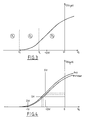
- FIG. 3 represents the variation of the current I DS flowing between the drain and the source of a TEGFET as a function of the voltage V G applied to its gate, the voltage V DS applied between the drain and the source of the transistor being constant.
- This figure shows a first zone Z1, called blocking zone, corresponding to the values of the gate voltage V G for which no current I DS flows in the transistor.
- a second zone Z2 called the saturation regime zone, appears for values of the gate voltage greater than a limit value V T , called the threshold value, but less than the value of the gate voltage V L beyond which begins a third zone Z3, called the linear regime zone, characterized by an affine law of variation of the current I DS as a function of the voltage V G.
- FIG. 4 also represents the variation of the drain-source current I DS as a function of the voltage V G applied to the gate for a constant value of the polarization V DS , but for two distinct values of a hydrostatic pressure P applied to the transistor .
- the value of the current I DS measured by preserving the polarization of the transistor 1 subjected to the pressure, that is to say by keeping constant the gate, drain and source potentials of this transistor, is in fact usable as signal representative of pressure P.
- this device comprises an adjustable voltage source 15 capable of providing a constant but adjustable drain potential V D , an adjustable voltage source 16 suitable for providing a constant but adjustable gate potential V G , and an ammeter 17 indicating the value of the current I DS .
- the source is also connected to a constant potential, for example that of the mass.
- This second measurement technique is illustrated by the horizontal line DH of FIG. 4 which, at two different values of the pressure, unequivocally corresponds two different values of the gate voltage V G for the same value of the current I DS .
- this device comprises a source of adjustable voltage 18 capable of providing a constant but adjustable drain potential V D , a resistance of value R, connected between the source of the transistor and the ground, and crossed by the current I DS , an adjustable voltage source 19 suitable for providing a reference potential equal to the product RI DS , a differential amplifier 20 whose inputs are connected to the source of transistor 1 and to voltage source 19, and whose output is connected to the gate of this transistor, and a voltmeter 21 indicating the value of the potential V G.
- the amplifier 20 adjusts the gate potential so that the voltage across the resistor R is constant, which fixes on the one hand the value of the potential of the source of transistor 1, and on the other hand share the value of the current I DS .
- the relative variation of the current I DS is maximum at the most negative values of the gate voltage, that is to say in the zone Z2 of saturation regime.
- the relative variation of the current I DS for an absolute variation of 1 kbar of the pressure is of the order of 14% when the transistor operates in linear mode (zone Z3), for a value of V G close to - 0.5 volts, whereas it can be greater than 50% when the transistor is operating in saturation mode, that is to say with a gate voltage barely greater than the threshold value V T.
- the gate potential at a value barely greater than the threshold voltage of the transistor, and the drain-source voltage at a value greater than the difference between the gate voltage and the threshold voltage, so that the transistor operates in saturation regime.
- a TEGFET it is possible to use a TEGFET to obtain a hydrostatic pressure measurement in the form of a frequency signal.
- the senor comprises an odd number of inverters produced by means of TEGFET transistors and Shottky diodes connected so as to constitute a ring oscillator, delivering a signal whose frequency is representative of the pressure conditions supported by these transistors.
- the transducer T of FIG. 8 comprises a substrate 101, produced in a binary alloy of elements from columns III and V of the Mendeleiev table, and preferably made of gallium arsenide GaAs, made semi-insulating for example by introduction of chromium.
- the thickness of this substrate is for example of the order of 300 micrometers and its resistivity is as high as possible.
- a buffer layer 102 On the substrate 101 is deposited by epitaxy a buffer layer 102, of the same composition as the substrate, and with a thickness of at least about 1 micrometer, the role of this layer being to provide the following layers with a bearing surface good flatness and good crystallographic quality.
- this separation layer can be constituted by an alloy In u Ga 1-u As v P 1-v .
- this layer is preferably made of gallium-aluminum arsenide Al u Ga 1-u As and its relative aluminum content (u) is, at its upper surface, at least equal to 0.25.
- this separation layer the thickness of which is of the order of a few hundredths of a micrometer, is to avoid the appearance of a two-dimensional layer of electrons at the interface with the next layer.
- an active layer 104 composed of the same elements as the separation layer, albeit in possibly different proportions, namely gallium-aluminum arsenide Al x Ga 1-x As for a substrate. in GaAs.
- the active layer which is sensitive to pressure, has a thickness of a few tenths of a micrometer to a few micrometers, and is doped with impurities from column IV A and / or from column VI A, more precisely by at least one of the elements Si, Ge, Sn, S, Se, and Te, at a total concentration between 2.1017 and 1020 atoms per cubic centimeter, so as to become the seat of a distribution three-dimensional electron.
- the active layer can be doped with silicon at a concentration of 1019 atoms per cubic centimeter.
- the relative aluminum content (x) of the sensitive layer 104 is between 0.25 and 0.40, more advantageously still between 0.27 and 0.37, and more precisely between 0.29 and 0.35, the values between 0.32 and 0.33 being optimal.
- the relative aluminum content (u) on the upper surface of the separation layer 103 which has already been specified to be at least 0.25, must also be at least equal to the relative content (x) of aluminum of the sensitive layer 104.
- the separation layer 103 may have a constant aluminum content over the entire thickness of this layer, or have an increasing gradient of aluminum content from its surface closest to the substrate towards its upper surface.
- each of the layers 102 to 104 extends a priori over the entire surface of the substrate 101: it is only by a subsequent etching operation that these layers can be formed into islands such as those which appear on the left and on the right of Figures 8 and 9; however, after the layers 102 to 104 have been deposited on the substrate 101, several solutions are possible.
- the first consists in etching these layers to obtain an island such as that which is formed in the left zone of the transducer of FIGS. 8 and 9, then to deposit on a second zone of the transducer, preferably an area in which the substrate has been exposed, a temperature probe capable of providing a signal representative of the temperature of the substrate, for example constituted by a thin metallic layer.
- Another possibility corresponding to the embodiment shown in FIGS. 8 and 9 and to the preferential use of a gallium arsenide substrate, consists, before any etching of the layers 102 to 104, of depositing other layers on these last, as described below.
- An insulation layer 105 undoped, consisting of gallium-aluminum arsenide Al z Ga 1-z As whose relative aluminum content (z) is for example between 0.40 and 0.50, is deposited by epitaxy on the layer pressure sensitive 104.
- a temperature sensitive layer 106 consisting of gallium-aluminum arsenide Al y Ga 1-y As whose relative aluminum content (y) is included. between 0 and 0.25 or between 0.45 and 1.
- the layers sensitive to pressure 104, and to temperature 106 are therefore stacked one on the other and separated by the insulating layer 105, the latter being separated from the substrate by the layer sensitive to pressure 104 and by the buffer 102 and separation layers 103.
- the aluminum content of the insulation layer is chosen so that the electronic barriers between this layer and each of the sensitive layers are maximum.
- the layers 104, 105, and 106 have a thickness of the order of 2 micrometers.
- the temperature sensitive layer 106 is, like the pressure sensitive layer, doped of type n by impurities from column IV A and / or from the column VI A, more precisely by at least one of the elements Si, Ge, Sn, S, Se, and Te, silicon and tin, constituting the most typical examples.
- a layer 107 of gallium arsenide GaAs called “contact recovery layer”, with a thickness of 5 to 50 nanometers, allowing good contact to be established. electric between a metallization layer 108 which covers it and one or the other of the layers sensitive to pressure 104 and to temperature 106.
- the metallization layer 108 for example made of gold - germanium - nickel alloyed around 450 ° C or 500 ° C, constitutes separate pads 108a, 108b, 108c, and 108d.
- the layers 107 to 102 deposited on the substrate 101 are cut so as to form two islands, appearing respectively in the first zone 101a, on the right of FIGS. 8 and 9, and in the second zone 101b, on the left.
- the upper layers 107 to 105 are removed, with the exception of the metallization pads, so that outside of these, the pressure-sensitive layer 4 constitutes the outer layer.
- the geometry of the assembly is such that the distance between the studs of the first zone is very advantageously less than twice the quantity represented by the square root of: rho0.e0 / ((rho1 / e1) + (rho2 / e2) ), in which rho0, rho1, and rho2 are the respective resistivities of the insulation layer 105, of the temperature-sensitive layer 106 (which is furthest from the substrate), and of the pressure-sensitive layer 104 (which is closest to the substrate), and in which e0, e1, and e2 are the respective thicknesses of the insulation layer, of the sensitive layer farthest from the substrate, and of the layer closest to the substrate.
- the distance between the pads of the second zone is, for its part, preferably greater than this same quantity.
- the voltage between the pads 108a and 108b is essentially representative of the temperature of the transducer T that constitutes the described structure, therefore in particular of the substrate 101, while the voltage between the pads 108c and 108d is essentially representative of the pressure to which this transducer is subjected.
- the signal representative of the temperature can be used, in a manner known per se, but with an efficiency proper to the present invention, to correct the signal representative of the pressure, without problems of heterogeneity of the environment of the sensitive layers appearing. present in the transducer.
- the conduction channel of the first zone is narrower than the conduction channel of the second zone, so that these two channels have electrical resistances of the same order of magnitude.
- passivate the transducer After etching, carried out in accordance with the above indications, it is very preferable, as is generally known in the field of semiconductors, to passivate the transducer.
- the latter is carried out by depositing a passivation layer which covers the entire structure, then by a selective opening of this passivation layer, making it possible to expose only the pads 108a to 108d, the latter subsequently receiving a new layer. of metallization which exceeds the level of the passivation layer.
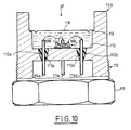
- FIG. 10 shows a possible mounting mode of a transducer according to the present invention.
- the transducer support consists of a piece of steel 109 which, with the exception of a thread 110 and a flat head 111 allowing it to be screwed, a flat transverse support surface 112 and a internal peripheral offset 113, is of substantially cylindrical shape.
- the transducer T is, on the side of the step, bonded by means of a flexible adhesive to the bearing surface 112, in which four bores 112a, 112b, 112c, 112d are made, two of which are visible in FIG. 10.
- a through electrical terminal, such as 114a, 114b, 114c is maintained in each of the bores by means of a glass bead such as 115a, 115b, which on the one hand ensures the attachment of each terminal with the bearing surface 112 , on the other hand the electrical insulation of this terminal and this surface, and finally a sealed closure of the bores 112a to 112d.
- each electrical terminal is connected to a pad such as 108c or 108d of the transducer T, the assembly being embedded in a volume of insulating oil closed by a deformable membrane of steel 116 welded to the recess 113.
- the part 109 thus designed can be screwed onto the wall of any enclosure in which there is a pressure P to be measured.
- the latter transmitted through the deformable membrane 116 to the volume of oil bathing the transducer, submits the latter to a hydrostatic pressure and a temperature which are measured by virtue of the resistance variations detected, at the terminals 114a to 114d outside the enclosure.
Landscapes
- Physics & Mathematics (AREA)
- General Physics & Mathematics (AREA)
- Measuring Fluid Pressure (AREA)
- Pressure Sensors (AREA)
Applications Claiming Priority (4)
| Application Number | Priority Date | Filing Date | Title |
|---|---|---|---|
| FR8804176A FR2629640B1 (fr) | 1988-03-30 | 1988-03-30 | Transducteur de pression hydrostatique a correction de temperature |
| FR8804175A FR2629592B1 (fr) | 1988-03-30 | 1988-03-30 | Capteur de pression adaptatif |
| FR8804175 | 1988-03-30 | ||
| FR8804176 | 1988-03-30 |
Publications (2)
| Publication Number | Publication Date |
|---|---|
| EP0335793A1 true EP0335793A1 (de) | 1989-10-04 |
| EP0335793B1 EP0335793B1 (de) | 1992-05-20 |
Family
ID=26226588
Family Applications (1)
| Application Number | Title | Priority Date | Filing Date |
|---|---|---|---|
| EP89400864A Expired - Lifetime EP0335793B1 (de) | 1988-03-30 | 1989-03-29 | Halbleiter-Druckwandler |
Country Status (4)
| Country | Link |
|---|---|
| US (1) | US4965697A (de) |
| EP (1) | EP0335793B1 (de) |
| DE (1) | DE68901571D1 (de) |
| ES (1) | ES2032119T3 (de) |
Cited By (3)
| Publication number | Priority date | Publication date | Assignee | Title |
|---|---|---|---|---|
| DE4238545A1 (de) * | 1992-11-14 | 1994-05-19 | Daimler Benz Ag | Drucksensor und ein Verfahren zu dessen Herstellung |
| RU2141103C1 (ru) * | 1998-03-12 | 1999-11-10 | Государственное научно-производственное предприятие "НИИПП" | Чувствительный элемент датчика давления |
| CN113029508A (zh) * | 2021-03-24 | 2021-06-25 | 中国空气动力研究与发展中心高速空气动力研究所 | 一种用于风洞模型底部压力测量的微型组合式压力传感器 |
Families Citing this family (18)
| Publication number | Priority date | Publication date | Assignee | Title |
|---|---|---|---|---|
| FR2653197B1 (fr) * | 1989-10-12 | 1991-12-27 | Vulcanic | Procede d'etancheification d'une extremite d'element de chauffage electrique et element etancheifie par ce procede. |
| JP3116409B2 (ja) * | 1991-05-07 | 2000-12-11 | 株式会社デンソー | 半導体歪みセンサ |
| US5413179A (en) * | 1993-04-16 | 1995-05-09 | The Energex Company | System and method for monitoring fracture growth during hydraulic fracture treatment |
| US5322126A (en) * | 1993-04-16 | 1994-06-21 | The Energex Company | System and method for monitoring fracture growth during hydraulic fracture treatment |
| EP0695927A3 (de) * | 1994-08-01 | 1996-06-26 | Motorola Inc | Detektor-Umformer unter Verwendung eines Schottky-Übergangs mit einer erhöhten Ausgangsspannung |
| US5863185A (en) * | 1994-10-05 | 1999-01-26 | Franklin Electric Co. | Liquid pumping system with cooled control module |
| US5925825A (en) * | 1994-10-05 | 1999-07-20 | Franklin Electric Co., Inc. | Clamp and cup securing strain gauge cell adjacent pressure transmitting diaphragm |
| US5635712A (en) * | 1995-05-04 | 1997-06-03 | Halliburton Company | Method for monitoring the hydraulic fracturing of a subterranean formation |
| US5831170A (en) * | 1996-04-04 | 1998-11-03 | Ssi Technologies, Inc. | Pressure sensor package and method of making the same |
| US5874679A (en) * | 1996-04-04 | 1999-02-23 | Ssi Technologies, Inc. | Pressure sensor package and method of making the same |
| EP0800070B1 (de) * | 1996-04-04 | 2001-08-22 | Ssi Technologies, Inc. | Druckmessgerät und Verfahren zu seiner Herstellung |
| US7127949B2 (en) | 2003-07-08 | 2006-10-31 | National University Of Singapore | Contact pressure sensor and method for manufacturing the same |
| JP4447871B2 (ja) * | 2003-08-29 | 2010-04-07 | キヤノン株式会社 | 画像形成装置 |
| US6928878B1 (en) * | 2004-09-28 | 2005-08-16 | Rosemount Aerospace Inc. | Pressure sensor |
| US8082796B1 (en) * | 2008-01-28 | 2011-12-27 | Silicon Microstructures, Inc. | Temperature extraction from a pressure sensor |
| EP3426147B1 (de) * | 2016-03-10 | 2020-06-17 | Epitronic Holdings Pte. Ltd. | Mikroelektronischer sensor für darmdiagnostika und überwachung der darmtätigkeit |
| US11000203B2 (en) | 2016-03-10 | 2021-05-11 | Epitronic Holdings Pte Ltd. | Microelectronic sensor for intestinal and gut diagnostics and gut motility monitoring |
| GB2559338A (en) * | 2017-01-31 | 2018-08-08 | Philip Sperring Christopher | Contact pressure sensor manufacture |
Citations (4)
| Publication number | Priority date | Publication date | Assignee | Title |
|---|---|---|---|---|
| GB1049130A (en) * | 1964-03-12 | 1966-11-23 | Intermetall Ges Fur Metallurg | Improvements in pressure transducers and circuit arrangements therefor |
| DE2714032A1 (de) * | 1977-03-30 | 1978-10-05 | Gni I Pi Redkometallitscheskoj | Halbleiterdruckgeber |
| DE3212026A1 (de) * | 1982-03-31 | 1983-10-06 | Siemens Ag | Temperatursensor |
| DE3211968A1 (de) * | 1982-03-31 | 1983-10-13 | Siemens AG, 1000 Berlin und 8000 München | Drucksensor |
Family Cites Families (2)
| Publication number | Priority date | Publication date | Assignee | Title |
|---|---|---|---|---|
| CH250406A (de) * | 1944-05-16 | 1947-08-31 | Philips Nv | Kapazitiver Druckaufnehmer. |
| US4196632A (en) * | 1978-08-14 | 1980-04-08 | The Boeing Company | Dual capacitance type bonded pressure transducer |
-
1989
- 1989-03-29 DE DE8989400864T patent/DE68901571D1/de not_active Expired - Fee Related
- 1989-03-29 EP EP89400864A patent/EP0335793B1/de not_active Expired - Lifetime
- 1989-03-29 US US07/330,249 patent/US4965697A/en not_active Expired - Lifetime
- 1989-03-29 ES ES198989400864T patent/ES2032119T3/es not_active Expired - Lifetime
Patent Citations (4)
| Publication number | Priority date | Publication date | Assignee | Title |
|---|---|---|---|---|
| GB1049130A (en) * | 1964-03-12 | 1966-11-23 | Intermetall Ges Fur Metallurg | Improvements in pressure transducers and circuit arrangements therefor |
| DE2714032A1 (de) * | 1977-03-30 | 1978-10-05 | Gni I Pi Redkometallitscheskoj | Halbleiterdruckgeber |
| DE3212026A1 (de) * | 1982-03-31 | 1983-10-06 | Siemens Ag | Temperatursensor |
| DE3211968A1 (de) * | 1982-03-31 | 1983-10-13 | Siemens AG, 1000 Berlin und 8000 München | Drucksensor |
Non-Patent Citations (2)
| Title |
|---|
| ELECTRONICS LETTERS, vol. 18, no. 15, 22 juillet 1982, pages 644-645, Londres, GB; A.K. SAXENA: "Ga1-xAlxAs material for high sensitivity pressure sensors" * |
| ELECTRONICS LETTERS, vol. 18, no. 18, 2 septembre 1982, pages 794-796, Londres, GB; S.L. SU et al.: "Modulation-doped (Al,Ga)As/GaAs fets with high transconductance and electron velocity" * |
Cited By (4)
| Publication number | Priority date | Publication date | Assignee | Title |
|---|---|---|---|---|
| DE4238545A1 (de) * | 1992-11-14 | 1994-05-19 | Daimler Benz Ag | Drucksensor und ein Verfahren zu dessen Herstellung |
| RU2141103C1 (ru) * | 1998-03-12 | 1999-11-10 | Государственное научно-производственное предприятие "НИИПП" | Чувствительный элемент датчика давления |
| CN113029508A (zh) * | 2021-03-24 | 2021-06-25 | 中国空气动力研究与发展中心高速空气动力研究所 | 一种用于风洞模型底部压力测量的微型组合式压力传感器 |
| CN113029508B (zh) * | 2021-03-24 | 2023-06-02 | 中国空气动力研究与发展中心高速空气动力研究所 | 一种用于风洞模型底部压力测量的微型组合式压力传感器 |
Also Published As
| Publication number | Publication date |
|---|---|
| DE68901571D1 (de) | 1992-06-25 |
| EP0335793B1 (de) | 1992-05-20 |
| ES2032119T3 (es) | 1993-01-01 |
| US4965697A (en) | 1990-10-23 |
Similar Documents
| Publication | Publication Date | Title |
|---|---|---|
| EP0335793B1 (de) | Halbleiter-Druckwandler | |
| EP0267069B1 (de) | Verfahren zur Herstellung eines Dehnungsmessstreifens mit Piezowiderstand, sowie eines Beschleunigungsmessers mit einem solchen Dehnungsmessstreifen | |
| EP0572298A1 (de) | Halleffekt-Fühler | |
| EP0194953B1 (de) | Integrierter kapazitiver Sensor für mechanische Grössen und dessen Fabrikationsverfahren | |
| EP1133683B1 (de) | Druckwandler mit einer siliziumkarbidenthaltenden membran und verfahren zu seiner herstellung | |
| FR2950969A1 (fr) | Dispositif de detection de variations de temperature dans une puce | |
| EP2267893B1 (de) | Volumenwellenresonator mit teilweise gefüllten Kavitäten | |
| CH656010A5 (fr) | Dispositif miniature sensible au champ magnetique et appareil de mesure du champ magnetique comportant un tel dispositif. | |
| EP2801117B1 (de) | Halbleiterstruktur, vorrichtung mit dieser halbleiterstruktur und herstellungsverfahren der halbleiterstruktur | |
| EP1314211B1 (de) | Halleffekt-sensor | |
| FR2942660A1 (fr) | Dispositif capteur a base de nanofils | |
| EP3396720B1 (de) | Herstellungsverfahren einer fotodiodenmatrix mit mesa-strukturen | |
| EP0454544B1 (de) | Hydrostatischer Druckwandler | |
| FR2650389A1 (fr) | Dispositif de mesure de deformation d'une membrane | |
| EP0019511B1 (de) | Verfahren zur Temperaturkompensation bei Oberflächenwellen-Vorrichtungen und Druckaufnehmer zur Durchführung des Verfahrens | |
| EP3803299B1 (de) | Sensitives pixelbasiertes detektionssystem mit einem thermischen detektor und einer kompensationsvorrichtung | |
| EP3633336B1 (de) | Pyroelektrische detektionsvorrichtung mit starrer membran | |
| EP3598512B1 (de) | Pyroelektrische detektionsvorrichtung mit vorgespannt aufgehängter membran | |
| FR2965105A1 (fr) | Detecteur bispectral multicouche a photodiodes | |
| FR2629640A1 (fr) | Transducteur de pression hydrostatique a correction de temperature | |
| FR2629592A1 (fr) | Capteur de pression adaptatif | |
| EP3455637B1 (de) | Vorgespannter vibrierender beschleunigungsmesser | |
| FR2711430A1 (fr) | Détecteur de rayonnement utilisant du diamant. | |
| EP3627103B1 (de) | Messvorrichtung, die einen aufgehängten halbleiterdraht umfasst | |
| FR2947628A1 (fr) | Procede de fabrication d'une jauge de deformation en circuit integre |
Legal Events
| Date | Code | Title | Description |
|---|---|---|---|
| PUAI | Public reference made under article 153(3) epc to a published international application that has entered the european phase |
Free format text: ORIGINAL CODE: 0009012 |
|
| AK | Designated contracting states |
Kind code of ref document: A1 Designated state(s): CH DE ES FR GB IT LI NL SE |
|
| 17P | Request for examination filed |
Effective date: 19891230 |
|
| 17Q | First examination report despatched |
Effective date: 19910502 |
|
| GRAA | (expected) grant |
Free format text: ORIGINAL CODE: 0009210 |
|
| AK | Designated contracting states |
Kind code of ref document: B1 Designated state(s): CH DE ES FR GB IT LI NL SE |
|
| ITF | It: translation for a ep patent filed | ||
| REF | Corresponds to: |
Ref document number: 68901571 Country of ref document: DE Date of ref document: 19920625 |
|
| GBT | Gb: translation of ep patent filed (gb section 77(6)(a)/1977) | ||
| REG | Reference to a national code |
Ref country code: ES Ref legal event code: FG2A Ref document number: 2032119 Country of ref document: ES Kind code of ref document: T3 |
|
| PGFP | Annual fee paid to national office [announced via postgrant information from national office to epo] |
Ref country code: ES Payment date: 19930224 Year of fee payment: 5 |
|
| PLBE | No opposition filed within time limit |
Free format text: ORIGINAL CODE: 0009261 |
|
| STAA | Information on the status of an ep patent application or granted ep patent |
Free format text: STATUS: NO OPPOSITION FILED WITHIN TIME LIMIT |
|
| 26N | No opposition filed | ||
| PGFP | Annual fee paid to national office [announced via postgrant information from national office to epo] |
Ref country code: SE Payment date: 19940325 Year of fee payment: 6 |
|
| PG25 | Lapsed in a contracting state [announced via postgrant information from national office to epo] |
Ref country code: ES Free format text: LAPSE BECAUSE OF NON-PAYMENT OF DUE FEES Effective date: 19940330 |
|
| EAL | Se: european patent in force in sweden |
Ref document number: 89400864.8 |
|
| PG25 | Lapsed in a contracting state [announced via postgrant information from national office to epo] |
Ref country code: SE Effective date: 19950330 |
|
| EUG | Se: european patent has lapsed |
Ref document number: 89400864.8 |
|
| PGFP | Annual fee paid to national office [announced via postgrant information from national office to epo] |
Ref country code: GB Payment date: 19980129 Year of fee payment: 10 |
|
| PGFP | Annual fee paid to national office [announced via postgrant information from national office to epo] |
Ref country code: NL Payment date: 19980330 Year of fee payment: 10 |
|
| PGFP | Annual fee paid to national office [announced via postgrant information from national office to epo] |
Ref country code: DE Payment date: 19980511 Year of fee payment: 10 |
|
| PG25 | Lapsed in a contracting state [announced via postgrant information from national office to epo] |
Ref country code: GB Free format text: LAPSE BECAUSE OF NON-PAYMENT OF DUE FEES Effective date: 19990329 |
|
| REG | Reference to a national code |
Ref country code: ES Ref legal event code: FD2A Effective date: 19990405 |
|
| PG25 | Lapsed in a contracting state [announced via postgrant information from national office to epo] |
Ref country code: NL Free format text: LAPSE BECAUSE OF NON-PAYMENT OF DUE FEES Effective date: 19991001 |
|
| GBPC | Gb: european patent ceased through non-payment of renewal fee |
Effective date: 19990329 |
|
| NLV4 | Nl: lapsed or anulled due to non-payment of the annual fee |
Effective date: 19991001 |
|
| PG25 | Lapsed in a contracting state [announced via postgrant information from national office to epo] |
Ref country code: DE Free format text: LAPSE BECAUSE OF NON-PAYMENT OF DUE FEES Effective date: 20000101 |
|
| PGFP | Annual fee paid to national office [announced via postgrant information from national office to epo] |
Ref country code: CH Payment date: 20020412 Year of fee payment: 14 |
|
| PG25 | Lapsed in a contracting state [announced via postgrant information from national office to epo] |
Ref country code: LI Free format text: LAPSE BECAUSE OF NON-PAYMENT OF DUE FEES Effective date: 20030331 Ref country code: CH Free format text: LAPSE BECAUSE OF NON-PAYMENT OF DUE FEES Effective date: 20030331 |
|
| REG | Reference to a national code |
Ref country code: CH Ref legal event code: PL |
|
| PG25 | Lapsed in a contracting state [announced via postgrant information from national office to epo] |
Ref country code: IT Free format text: LAPSE BECAUSE OF NON-PAYMENT OF DUE FEES;WARNING: LAPSES OF ITALIAN PATENTS WITH EFFECTIVE DATE BEFORE 2007 MAY HAVE OCCURRED AT ANY TIME BEFORE 2007. THE CORRECT EFFECTIVE DATE MAY BE DIFFERENT FROM THE ONE RECORDED. Effective date: 20050329 |
|
| PGFP | Annual fee paid to national office [announced via postgrant information from national office to epo] |
Ref country code: FR Payment date: 20060222 Year of fee payment: 18 |
|
| REG | Reference to a national code |
Ref country code: FR Ref legal event code: ST Effective date: 20071130 |
|
| PG25 | Lapsed in a contracting state [announced via postgrant information from national office to epo] |
Ref country code: FR Free format text: LAPSE BECAUSE OF NON-PAYMENT OF DUE FEES Effective date: 20070402 |