EP0335793A1 - Semiconductor pressure transducer - Google Patents
Semiconductor pressure transducer Download PDFInfo
- Publication number
- EP0335793A1 EP0335793A1 EP89400864A EP89400864A EP0335793A1 EP 0335793 A1 EP0335793 A1 EP 0335793A1 EP 89400864 A EP89400864 A EP 89400864A EP 89400864 A EP89400864 A EP 89400864A EP 0335793 A1 EP0335793 A1 EP 0335793A1
- Authority
- EP
- European Patent Office
- Prior art keywords
- layer
- pressure
- substrate
- sensitive
- gallium
- Prior art date
- Legal status (The legal status is an assumption and is not a legal conclusion. Google has not performed a legal analysis and makes no representation as to the accuracy of the status listed.)
- Granted
Links
- 239000004065 semiconductor Substances 0.000 title claims abstract description 13
- 239000000758 substrate Substances 0.000 claims abstract description 50
- 230000002706 hydrostatic effect Effects 0.000 claims abstract description 40
- MDPILPRLPQYEEN-UHFFFAOYSA-N aluminium arsenide Chemical compound [As]#[Al] MDPILPRLPQYEEN-UHFFFAOYSA-N 0.000 claims abstract description 28
- JBRZTFJDHDCESZ-UHFFFAOYSA-N AsGa Chemical compound [As]#[Ga] JBRZTFJDHDCESZ-UHFFFAOYSA-N 0.000 claims abstract description 21
- 229910001218 Gallium arsenide Inorganic materials 0.000 claims abstract description 20
- 238000005259 measurement Methods 0.000 claims abstract description 12
- 229910052782 aluminium Inorganic materials 0.000 claims description 30
- XAGFODPZIPBFFR-UHFFFAOYSA-N aluminium Chemical compound [Al] XAGFODPZIPBFFR-UHFFFAOYSA-N 0.000 claims description 28
- 239000008186 active pharmaceutical agent Substances 0.000 claims description 18
- 238000000407 epitaxy Methods 0.000 claims description 17
- 238000000034 method Methods 0.000 claims description 17
- 238000009413 insulation Methods 0.000 claims description 15
- 229910045601 alloy Inorganic materials 0.000 claims description 13
- 239000000956 alloy Substances 0.000 claims description 13
- 238000009826 distribution Methods 0.000 claims description 10
- 239000012535 impurity Substances 0.000 claims description 9
- 230000000737 periodic effect Effects 0.000 claims description 9
- 101150069512 RHO1 gene Proteins 0.000 claims description 8
- 101150012845 RHO2 gene Proteins 0.000 claims description 8
- 230000005669 field effect Effects 0.000 claims description 8
- 230000008859 change Effects 0.000 claims description 4
- 229910052751 metal Inorganic materials 0.000 claims description 3
- 239000002184 metal Substances 0.000 claims description 3
- 230000004044 response Effects 0.000 claims description 3
- GYHNNYVSQQEPJS-UHFFFAOYSA-N Gallium Chemical compound [Ga] GYHNNYVSQQEPJS-UHFFFAOYSA-N 0.000 abstract description 2
- 229910052733 gallium Inorganic materials 0.000 abstract description 2
- 229910052710 silicon Inorganic materials 0.000 description 14
- 238000000926 separation method Methods 0.000 description 12
- XUIMIQQOPSSXEZ-UHFFFAOYSA-N Silicon Chemical compound [Si] XUIMIQQOPSSXEZ-UHFFFAOYSA-N 0.000 description 9
- 239000010703 silicon Substances 0.000 description 9
- 239000012528 membrane Substances 0.000 description 8
- 239000000463 material Substances 0.000 description 7
- 229910052718 tin Inorganic materials 0.000 description 7
- 230000008901 benefit Effects 0.000 description 6
- 238000005530 etching Methods 0.000 description 6
- 238000000691 measurement method Methods 0.000 description 6
- 239000000523 sample Substances 0.000 description 6
- 229910052711 selenium Inorganic materials 0.000 description 6
- 239000011669 selenium Substances 0.000 description 6
- 229910052717 sulfur Inorganic materials 0.000 description 6
- 229910052714 tellurium Inorganic materials 0.000 description 6
- 229910052732 germanium Inorganic materials 0.000 description 5
- 229910000831 Steel Inorganic materials 0.000 description 4
- 238000010586 diagram Methods 0.000 description 4
- 238000001465 metallisation Methods 0.000 description 4
- 239000003921 oil Substances 0.000 description 4
- 230000035945 sensitivity Effects 0.000 description 4
- 239000010959 steel Substances 0.000 description 4
- 238000009530 blood pressure measurement Methods 0.000 description 3
- 238000012937 correction Methods 0.000 description 3
- 238000000151 deposition Methods 0.000 description 3
- 239000011521 glass Substances 0.000 description 3
- 230000007774 longterm Effects 0.000 description 3
- 238000004519 manufacturing process Methods 0.000 description 3
- 238000002161 passivation Methods 0.000 description 3
- ATJFFYVFTNAWJD-UHFFFAOYSA-N Tin Chemical compound [Sn] ATJFFYVFTNAWJD-UHFFFAOYSA-N 0.000 description 2
- 239000000853 adhesive Substances 0.000 description 2
- 230000001070 adhesive effect Effects 0.000 description 2
- 238000003287 bathing Methods 0.000 description 2
- 239000011324 bead Substances 0.000 description 2
- 230000007423 decrease Effects 0.000 description 2
- 230000000694 effects Effects 0.000 description 2
- 238000010292 electrical insulation Methods 0.000 description 2
- 238000002474 experimental method Methods 0.000 description 2
- 239000000203 mixture Substances 0.000 description 2
- 230000002093 peripheral effect Effects 0.000 description 2
- 230000010287 polarization Effects 0.000 description 2
- 230000008569 process Effects 0.000 description 2
- 238000011084 recovery Methods 0.000 description 2
- 238000012552 review Methods 0.000 description 2
- 230000005533 two-dimensional electron gas Effects 0.000 description 2
- PXFBZOLANLWPMH-UHFFFAOYSA-N 16-Epiaffinine Natural products C1C(C2=CC=CC=C2N2)=C2C(=O)CC2C(=CC)CN(C)C1C2CO PXFBZOLANLWPMH-UHFFFAOYSA-N 0.000 description 1
- RZVAJINKPMORJF-UHFFFAOYSA-N Acetaminophen Chemical compound CC(=O)NC1=CC=C(O)C=C1 RZVAJINKPMORJF-UHFFFAOYSA-N 0.000 description 1
- VYZAMTAEIAYCRO-UHFFFAOYSA-N Chromium Chemical compound [Cr] VYZAMTAEIAYCRO-UHFFFAOYSA-N 0.000 description 1
- GPXJNWSHGFTCBW-UHFFFAOYSA-N Indium phosphide Chemical compound [In]#P GPXJNWSHGFTCBW-UHFFFAOYSA-N 0.000 description 1
- BUGBHKTXTAQXES-UHFFFAOYSA-N Selenium Chemical compound [Se] BUGBHKTXTAQXES-UHFFFAOYSA-N 0.000 description 1
- NINIDFKCEFEMDL-UHFFFAOYSA-N Sulfur Chemical compound [S] NINIDFKCEFEMDL-UHFFFAOYSA-N 0.000 description 1
- MBGCACIOPCILDG-UHFFFAOYSA-N [Ni].[Ge].[Au] Chemical compound [Ni].[Ge].[Au] MBGCACIOPCILDG-UHFFFAOYSA-N 0.000 description 1
- 230000001154 acute effect Effects 0.000 description 1
- 230000006978 adaptation Effects 0.000 description 1
- 238000004458 analytical method Methods 0.000 description 1
- 229910052787 antimony Inorganic materials 0.000 description 1
- 230000004888 barrier function Effects 0.000 description 1
- 229910002056 binary alloy Inorganic materials 0.000 description 1
- 230000000903 blocking effect Effects 0.000 description 1
- 229910052804 chromium Inorganic materials 0.000 description 1
- 239000011651 chromium Substances 0.000 description 1
- 239000002131 composite material Substances 0.000 description 1
- 230000001419 dependent effect Effects 0.000 description 1
- 230000008021 deposition Effects 0.000 description 1
- 238000009792 diffusion process Methods 0.000 description 1
- 238000006073 displacement reaction Methods 0.000 description 1
- 238000005516 engineering process Methods 0.000 description 1
- 238000007667 floating Methods 0.000 description 1
- 230000036039 immunity Effects 0.000 description 1
- 238000002513 implantation Methods 0.000 description 1
- WPYVAWXEWQSOGY-UHFFFAOYSA-N indium antimonide Chemical compound [Sb]#[In] WPYVAWXEWQSOGY-UHFFFAOYSA-N 0.000 description 1
- RPQDHPTXJYYUPQ-UHFFFAOYSA-N indium arsenide Chemical compound [In]#[As] RPQDHPTXJYYUPQ-UHFFFAOYSA-N 0.000 description 1
- 238000009776 industrial production Methods 0.000 description 1
- 238000004377 microelectronic Methods 0.000 description 1
- 238000001451 molecular beam epitaxy Methods 0.000 description 1
- 230000005693 optoelectronics Effects 0.000 description 1
- 244000045947 parasite Species 0.000 description 1
- 239000005297 pyrex Substances 0.000 description 1
- 239000007787 solid Substances 0.000 description 1
- 238000007711 solidification Methods 0.000 description 1
- 230000008023 solidification Effects 0.000 description 1
- 239000011593 sulfur Substances 0.000 description 1
- PORWMNRCUJJQNO-UHFFFAOYSA-N tellurium atom Chemical compound [Te] PORWMNRCUJJQNO-UHFFFAOYSA-N 0.000 description 1
Images


Classifications
-
- H—ELECTRICITY
- H01—ELECTRIC ELEMENTS
- H01L—SEMICONDUCTOR DEVICES NOT COVERED BY CLASS H10
- H01L29/00—Semiconductor devices adapted for rectifying, amplifying, oscillating or switching, or capacitors or resistors with at least one potential-jump barrier or surface barrier, e.g. PN junction depletion layer or carrier concentration layer; Details of semiconductor bodies or of electrodes thereof ; Multistep manufacturing processes therefor
- H01L29/66—Types of semiconductor device ; Multistep manufacturing processes therefor
- H01L29/84—Types of semiconductor device ; Multistep manufacturing processes therefor controllable by variation of applied mechanical force, e.g. of pressure
-
- G—PHYSICS
- G01—MEASURING; TESTING
- G01D—MEASURING NOT SPECIALLY ADAPTED FOR A SPECIFIC VARIABLE; ARRANGEMENTS FOR MEASURING TWO OR MORE VARIABLES NOT COVERED IN A SINGLE OTHER SUBCLASS; TARIFF METERING APPARATUS; MEASURING OR TESTING NOT OTHERWISE PROVIDED FOR
- G01D3/00—Indicating or recording apparatus with provision for the special purposes referred to in the subgroups
- G01D3/028—Indicating or recording apparatus with provision for the special purposes referred to in the subgroups mitigating undesired influences, e.g. temperature, pressure
- G01D3/036—Indicating or recording apparatus with provision for the special purposes referred to in the subgroups mitigating undesired influences, e.g. temperature, pressure on measuring arrangements themselves
-
- G—PHYSICS
- G01—MEASURING; TESTING
- G01L—MEASURING FORCE, STRESS, TORQUE, WORK, MECHANICAL POWER, MECHANICAL EFFICIENCY, OR FLUID PRESSURE
- G01L19/00—Details of, or accessories for, apparatus for measuring steady or quasi-steady pressure of a fluent medium insofar as such details or accessories are not special to particular types of pressure gauges
- G01L19/06—Means for preventing overload or deleterious influence of the measured medium on the measuring device or vice versa
- G01L19/0627—Protection against aggressive medium in general
- G01L19/0645—Protection against aggressive medium in general using isolation membranes, specially adapted for protection
-
- G—PHYSICS
- G01—MEASURING; TESTING
- G01L—MEASURING FORCE, STRESS, TORQUE, WORK, MECHANICAL POWER, MECHANICAL EFFICIENCY, OR FLUID PRESSURE
- G01L19/00—Details of, or accessories for, apparatus for measuring steady or quasi-steady pressure of a fluent medium insofar as such details or accessories are not special to particular types of pressure gauges
- G01L19/14—Housings
- G01L19/141—Monolithic housings, e.g. molded or one-piece housings
-
- G—PHYSICS
- G01—MEASURING; TESTING
- G01L—MEASURING FORCE, STRESS, TORQUE, WORK, MECHANICAL POWER, MECHANICAL EFFICIENCY, OR FLUID PRESSURE
- G01L9/00—Measuring steady of quasi-steady pressure of fluid or fluent solid material by electric or magnetic pressure-sensitive elements; Transmitting or indicating the displacement of mechanical pressure-sensitive elements, used to measure the steady or quasi-steady pressure of a fluid or fluent solid material, by electric or magnetic means
- G01L9/0098—Measuring steady of quasi-steady pressure of fluid or fluent solid material by electric or magnetic pressure-sensitive elements; Transmitting or indicating the displacement of mechanical pressure-sensitive elements, used to measure the steady or quasi-steady pressure of a fluid or fluent solid material, by electric or magnetic means using semiconductor body comprising at least one PN junction as detecting element
-
- H—ELECTRICITY
- H01—ELECTRIC ELEMENTS
- H01L—SEMICONDUCTOR DEVICES NOT COVERED BY CLASS H10
- H01L2224/00—Indexing scheme for arrangements for connecting or disconnecting semiconductor or solid-state bodies and methods related thereto as covered by H01L24/00
- H01L2224/01—Means for bonding being attached to, or being formed on, the surface to be connected, e.g. chip-to-package, die-attach, "first-level" interconnects; Manufacturing methods related thereto
- H01L2224/42—Wire connectors; Manufacturing methods related thereto
- H01L2224/47—Structure, shape, material or disposition of the wire connectors after the connecting process
- H01L2224/48—Structure, shape, material or disposition of the wire connectors after the connecting process of an individual wire connector
- H01L2224/4805—Shape
- H01L2224/4809—Loop shape
- H01L2224/48091—Arched
-
- H—ELECTRICITY
- H01—ELECTRIC ELEMENTS
- H01L—SEMICONDUCTOR DEVICES NOT COVERED BY CLASS H10
- H01L2224/00—Indexing scheme for arrangements for connecting or disconnecting semiconductor or solid-state bodies and methods related thereto as covered by H01L24/00
- H01L2224/73—Means for bonding being of different types provided for in two or more of groups H01L2224/10, H01L2224/18, H01L2224/26, H01L2224/34, H01L2224/42, H01L2224/50, H01L2224/63, H01L2224/71
- H01L2224/732—Location after the connecting process
- H01L2224/73251—Location after the connecting process on different surfaces
- H01L2224/73265—Layer and wire connectors
-
- H—ELECTRICITY
- H01—ELECTRIC ELEMENTS
- H01L—SEMICONDUCTOR DEVICES NOT COVERED BY CLASS H10
- H01L2924/00—Indexing scheme for arrangements or methods for connecting or disconnecting semiconductor or solid-state bodies as covered by H01L24/00
- H01L2924/10—Details of semiconductor or other solid state devices to be connected
- H01L2924/11—Device type
- H01L2924/13—Discrete devices, e.g. 3 terminal devices
- H01L2924/1304—Transistor
- H01L2924/1306—Field-effect transistor [FET]
- H01L2924/13091—Metal-Oxide-Semiconductor Field-Effect Transistor [MOSFET]
Definitions
- the present invention relates to a semiconductor pressure sensor.
- the invention relates more particularly, but not exclusively, to a device sensitive to a hydrostatic pressure to which it is subjected, comprising at least a first layer of gallium-aluminum arsenide Al x Ga 1-x As whose relative aluminum content (x) is less than 0.25, and a second layer of gallium-aluminum arsenide Al y Ga 1-y As whose relative aluminum content (y) is greater than (x) and between 0.15 and 1, and in which is formed, at the interface of these two layers, a conduction channel whose electrical resistance varies as a function of the pressure undergone by this device.
- gallium arsenide - aluminum structures on a gallium arsenide substrate have already been the subject of several publications, and their behavior in pressure or in temperature has been described in particular in the following articles: - "Pressure and compositional dependences of the Hall coefficient in Al y Ga 1-y As and their significance", N. Lifshitz, A.Jayaraman, RALogan, Physical Review B, Vol. 21, No 2, (January 5, 1980), pp. 670 to 678; - "The conduction band structure and deep levels in Ga 1-y Al y As alloys from a high pressure experiment", A.Saxena, J. Phys. C: Solid State Phys. 13, (1980), pp.
- a characteristic of the known structures of this family is that a determined pressure variation leads to a corresponding relative variation in the resistivity of their sensitive layer, which is fixed once and for all by the nature of the material used. At room temperature, the limit is 45% per kilobar. As a result, the resolution of such structures, that is to say the smallest value of pressure variation that they are capable of detecting, is inextricably linked to the smallest detectable relative variation in the resistance of their sensitive layer. .
- Pressure sensors with strain gauges are also known, using piezoresistivity, in which the electrical resistance of each gauge varies as a function of the stress which it undergoes by application of the pressure.
- gauges which are not directly sensitive to hydrostatic pressure, must be associated with a particular conformation of the sensor, capable of converting the hydrostatic pressure to be measured in an anisotropic stress to which the gauges are only sensitive.
- a sensor of this type is not capable of adapting to several different ranges of average conditions Operating.
- one of the aims of the present invention is to provide a pressure sensor capable of dynamically adapting to different average measurement conditions and to present, for each of them, a resolution capable of being adjusted and taking high values.
- the invention provides a device, sensitive to hydrostatic pressure, comprising at least a first layer of gallium-aluminum arsenide Al x Ga 1-x As whose relative content (x) in aluminum is less than 0.25, and a second layer of gallium-aluminum arsenide Al y Ga 1-y As whose relative aluminum content (y) is greater than (x) and between 0.15 and 1, and in which forms, at the interface of these two layers, a conduction channel whose electrical resistance varies according to a pressure undergone by this device, the latter comprising a field effect transistor and two-dimensional electronic distribution (TEGFET), comprising a drain, a source and a grid.
- TEGFET field effect transistor and two-dimensional electronic distribution
- the layer of gallium-aluminum arsenide Al y Ga 1-y As is selectively doped with impurities from column IV A and / or from column VI A of the periodic table, for example at least one of the elements Si, Ge, Sn, S, Se, and Te, at a total concentration, integrated over the thickness of this layer, which is advantageously between 1012 and 1013 atoms per square centimeter.
- the invention according to this first aspect further provides a method for measuring a hydrostatic pressure comprising a first operation consisting in subjecting a pressure sensor to the pressure to be measured, a second operation consisting in collecting a response signal from the sensor, and a third operation consisting in deducing from this signal the value of this hydrostatic pressure by virtue of a known law connecting this signal to this value, this method being essentially characterized in that the first and second operations are carried out using a sensor which comprises at least one field effect transistor and two-dimensional electronic distribution (TEGFET), comprising a drain, a source and a grid.
- TEGFET field effect transistor and two-dimensional electronic distribution
- a device for implementing the second mentioned operation may include means for keeping the gate, drain and source potentials constant, and means for measuring the current flowing between the drain and the source.
- this second operation can also be implemented by means to keep the drain and source potentials constant, and by means for adjusting the gate potential so as to keep the current flowing between the drain and the source constant. .
- the device and the method of this first aspect of the invention are capable of adapting perfectly to the case where the conditions for measuring the hydrostatic pressure change, in particular by variation of this pressure itself or by variation of the temperature, in the vicinity of average measurement conditions, the method then comprising an operation consisting in adjusting, for these average measurement conditions, the gate potential to a value barely greater than the threshold voltage of the transistor, and the drain voltage -source at a value greater than the difference between the gate voltage and the threshold voltage, so that the transistor operates in saturation mode.
- the threshold voltage of the transistor is the gate voltage for which the drain-source current is canceled.
- a value barely higher than the threshold voltage is meant here a value exceeding by more than 1 volt the threshold voltage.
- the method of this first aspect of the invention can also be implemented in another form, in which the first operation consists essentially in subjecting to the hydrostatic pressure to be measured a set of two-dimensional electronic field effect transistors with electronic distribution. integrated into a circuit, known as a ring oscillator, produced by the connection of an odd number of elementary gates, themselves composed of transistors and Schottky diodes produced on the same substrate.
- the third operation then essentially consists in collecting the signal produced by this oscillator, and the frequency of which is representative of the pressure to be measured.
- the present invention relates more particularly, but not exclusively, to a hydrostatic pressure transducer, comprising at least one pressure-sensitive semiconductor layer which consists of an alloy of at least three elements from columns III and V of the periodic table and whose electrical resistance, varying with said pressure, has a value representative of the latter at constant temperature, this pressure-sensitive layer being integral with a substrate made of an alloy of two of said three elements and obtained by epitaxy.
- Pressure sensors based on semiconductors have been used for about twenty years. They usually use a structure comprising four silicon gauges arranged in a Wheatstone bridge, intentionally doped with acceptor impurities, so that they have a p-type conductivity, said gauges being produced by diffusion or implantation of the impurities in a n type conductivity silicon substrate.
- the effect used is piezoresistivity, which manifests itself in the fact that the electrical resistance of each gauge varies according to the stress which it undergoes by application of the pressure.
- sensors of this type are designed so that the application of hydrostatic pressure results in appearance of such constraints.
- these sensors comprise a membrane produced by etching one of their faces, which is brought to a reference pressure, while the other face, which supports the strain gauges, is brought to the hydrostatic pressure to be measured, of so that appears on this face a system of stresses mainly directed along the plane of the membrane.
- the resistance of two of the bridge gauges increases with the pressure applied, while the resistance of the other two decreases. Wheatstone bridge is then unbalanced and a pressure dependent signal can be obtained.
- the sensitive silicon element must be sealed under zero pressure, for example by a glass of Pyrex type.
- these known sensors reveal all the problems inherent in a composite structure, in particular problems of long-term stability and hysteresis.
- these materials are in particular the indium - antimony, gallium - antimony, aluminum - arsenic, indium - phosphorus, arsenic - gallium, arsenic - indium semiconductors, and their mixtures, n-doped by an element from columns IV or VI, in particular by silicon, tin, tellurium, sulfur or selenium.
- gallium arsenide - aluminum has been the subject of several publications, in particular the three publications mentioned above.
- the second aspect of the invention provides a simple means of compensating, as a function of temperature, for the output signal of a hydrostatic pressure sensor comprising an alloy of at least three elements from columns III and V the periodic table, allowing you to take advantage, even in an industrial environment, of the advantages these materials in their application to hydrostatic pressure sensors.
- the invention according to this second aspect is based on the fact that the limitations which apply to thermal probes in the case of sensors with piezoresistive silicon gauges do not apply in the case of sensors directly sensitive to pressure hydrostatic, of the type previously mentioned, due to the homogeneous structure of the latter.
- a hydrostatic pressure transducer which comprises at least one pressure-sensitive semiconductor layer, consisting of an alloy of at least three elements from columns III and V of the periodic table and of which the electrical resistance, varying with said pressure, has a value representative of the latter at constant temperature, this pressure-sensitive layer being integral with a substrate made of an alloy of at least two of said three elements and obtained by epitaxy, further includes a temperature sensor, supported by the same substrate and capable of providing a signal representative of the temperature of the latter.
- the pressure-sensitive layer consists of gallium-aluminum arsenide Al x Ga 1-x As whose relative aluminum content (x) is included between 0.25 and 0.40, and the substrate consists of gallium arsenide.
- the relative aluminum content (x) of the pressure-sensitive layer is between 0.27 and 0.37, and has an optimal value between 0.29 and 0.35, and more precisely still between 0.32 and 0.33.
- this pressure-sensitive layer is doped with impurities from column IV A and / or from column VI A of the periodic table, more particularly the elements Si, Ge, Sn, S, Se, and Te, to a total concentration between 2.1017 and 1020 atoms per cubic centimeter.
- the temperature sensor itself is essentially constituted by a semiconductor layer sensitive to temperature which has a three-dimensional distribution of electrons, which consists of an alloy of the same elements than those of the pressure-sensitive layer, and whose electrical resistance, varying with the temperature of the substrate, has a value representative of the latter at constant pressure, this temperature-sensitive layer also being obtained by epitaxy.
- the temperature-sensitive layer preferably also consists of gallium-aluminum arsenide Al y Ga 1-y As, with a relative content (y) aluminum between 0 and 0.25 or between 0.45 and 1.
- said pressure and temperature sensitive layers can be stacked on top of each other and separated by an insulation layer.
- This insulation layer is preferably undoped, formed by epitaxy, consisting of gallium-aluminum arsenide Al z Ga 1-z As whose relative aluminum content (z) is between 0.40 and 0.50, and separated from the substrate. at least by the pressure-sensitive layer.
- the transducer of this second aspect of the invention comprises a first zone in which the sensitive and insulating layers are stacked on each other, and a second zone, laterally displaced relative to the first, in which at least the upper sensitive layer has at least been partially removed; it further comprises a first pair of metallic contacts established in the first zone, separated from each other by a first distance, and a second pair of metallic contacts established in the second zone, separated from each other by a second distance.
- the first distance is advantageously less than twice the quantity represented by the square root of: rho0.e0 / ((rho1 / e1) + (rho2 / e2)), in which rho0, rho1 and rho2 are the respective resistivities of the layer of insulation, of the sensitive layer furthest from the substrate, and of the layer closest to the substrate, and in which e0, e1, and e2 are the respective thicknesses of the insulation layer, of the most sensitive layer away from the substrate, and the layer closest to the substrate.
- the second distance is then greater than this same amount.
- TEGFET transistors such as that shown in Figure 1
- Two-dimensional Electron Gas Field Effect Transistor that is to say transistor with field effect and two-dimensional electronic distribution.
- TEGFET 1 in Figure 1 The structure of TEGFET 1 in Figure 1 is more precisely as follows.
- the substrate 2 is formed from a semi-insulating gallium arsenide GaAs wafer, with a thickness of the order of 300 micrometers for example.
- a layer 3 of gallop arsenide GaAs undoped On this substrate is deposited by epitaxy a layer 3 of gallop arsenide GaAs undoped, with a thickness of 1 to a few micrometers, constituting a buffer layer intended to offer a good surface condition to the subsequent layers.
- this buffer layer 3 can be deposited by epitaxy an additional layer (not shown), of gallium-aluminum arsenide Al x Ga 1-x As undoped, whose relative aluminum content (x) is less than 0.25 and whose l thickness is for example of the order of a few tenths of a micrometer.
- the buffer layer 3, whether or not covered with this additional layer, therefore constitutes a layer of gallium-aluminum arsenide Al x Ga 1-x As undoped, the relative aluminum content (x) of which is possibly zero. less than 0.25.
- this separation layer 4 On the buffer layer 3 or on this optional additional layer, not shown, is deposited, also by epitaxy, a separation layer 4 of gallium-aluminum arsenide Al y Ga 1-y As undoped, the relative content of which (y) aluminum is greater than (x) and between 0.15 and 1.
- the thickness of this separation layer 4 is for example of the order of 0 to 30 nanometers.
- a layer 5 of gallium-aluminum arsenide Al y Ga 1-y As doped the content of which relative (y) aluminum is substantially the same as that of the separation layer 4, and whose thickness is for example between 30 and 100 nanometers.
- Layer 5 can be doped with impurities from column IV A and / or column VI A of the periodic table, in particular by at least one of the elements Si, Ge, Sn, S, Se, and Te, at a total concentration, integrated over the thickness of this layer, between 1012 and 1013 atoms per square centimeter.
- a two-dimensional electron gas appears at the interface formed by layers 4 and 5 of gallium-aluminum arsenide Al y Ga 1-y As with layer 3, and its possible additional layer, of gallium-aluminum arsenide Al x Ga 1-x As.
- Layer 5 is, in known manner, covered with a contact recovery layer of GaAs gallium arsenide, then etched to present a central depression 5a, after which metal studs 6a, 6b, 6c, intended respectively to constitute the drain , the gate, and the source of the transistor, are deposited.
- FIG. 2 represents a possible mounting mode of the TEGFET transistor as a hydrostatic pressure sensor.
- the support of the transistor 1 consists of a piece of steel 7 which, with the exception of a thread 8 and a flat head 9 allowing it to be screwed, has a flat transverse support surface lo and an internal peripheral offset is of substantially cylindrical shape.
- the transducer 1 is, on the side of the step, bonded by means of a flexible adhesive to the bearing surface 10, in which three bores 10a, 10b, 10c are made, two of which are visible in FIG. 2.
- a through electrical terminal, such as 12a, 12b, 12c is maintained in each of the bores by means of a glass bead such as 13a, 13b, 13c, which ensures on the one hand the solidification of each terminal with the surface of support 10, on the other hand the electrical insulation of this terminal and this surface, and finally a sealed closure of the bores 10a to 10c.
- each electrical terminal is connected to a pad such as 6a, 6b, or 6c of the transistor 1, the assembly being embedded in a volume of insulating oil closed by a deformable membrane of steel 14 welded on the recess 11.
- the part 7 thus designed can be screwed onto the wall of any enclosure in which there is a pressure P to be measured.
- the latter transmitted through the deformable membrane 14 to the volume of oil bathing the transistor, subjects the latter to hydrostatic pressure and temperature conditions which it is possible, in accordance with the teaching of the invention, to measure optimally as described below with reference to Figures 3 and 4.
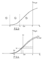
- FIG. 3 represents the variation of the current I DS flowing between the drain and the source of a TEGFET as a function of the voltage V G applied to its gate, the voltage V DS applied between the drain and the source of the transistor being constant.
- This figure shows a first zone Z1, called blocking zone, corresponding to the values of the gate voltage V G for which no current I DS flows in the transistor.
- a second zone Z2 called the saturation regime zone, appears for values of the gate voltage greater than a limit value V T , called the threshold value, but less than the value of the gate voltage V L beyond which begins a third zone Z3, called the linear regime zone, characterized by an affine law of variation of the current I DS as a function of the voltage V G.
- FIG. 4 also represents the variation of the drain-source current I DS as a function of the voltage V G applied to the gate for a constant value of the polarization V DS , but for two distinct values of a hydrostatic pressure P applied to the transistor .
- the value of the current I DS measured by preserving the polarization of the transistor 1 subjected to the pressure, that is to say by keeping constant the gate, drain and source potentials of this transistor, is in fact usable as signal representative of pressure P.
- this device comprises an adjustable voltage source 15 capable of providing a constant but adjustable drain potential V D , an adjustable voltage source 16 suitable for providing a constant but adjustable gate potential V G , and an ammeter 17 indicating the value of the current I DS .
- the source is also connected to a constant potential, for example that of the mass.
- This second measurement technique is illustrated by the horizontal line DH of FIG. 4 which, at two different values of the pressure, unequivocally corresponds two different values of the gate voltage V G for the same value of the current I DS .
- this device comprises a source of adjustable voltage 18 capable of providing a constant but adjustable drain potential V D , a resistance of value R, connected between the source of the transistor and the ground, and crossed by the current I DS , an adjustable voltage source 19 suitable for providing a reference potential equal to the product RI DS , a differential amplifier 20 whose inputs are connected to the source of transistor 1 and to voltage source 19, and whose output is connected to the gate of this transistor, and a voltmeter 21 indicating the value of the potential V G.
- the amplifier 20 adjusts the gate potential so that the voltage across the resistor R is constant, which fixes on the one hand the value of the potential of the source of transistor 1, and on the other hand share the value of the current I DS .
- the relative variation of the current I DS is maximum at the most negative values of the gate voltage, that is to say in the zone Z2 of saturation regime.
- the relative variation of the current I DS for an absolute variation of 1 kbar of the pressure is of the order of 14% when the transistor operates in linear mode (zone Z3), for a value of V G close to - 0.5 volts, whereas it can be greater than 50% when the transistor is operating in saturation mode, that is to say with a gate voltage barely greater than the threshold value V T.
- the gate potential at a value barely greater than the threshold voltage of the transistor, and the drain-source voltage at a value greater than the difference between the gate voltage and the threshold voltage, so that the transistor operates in saturation regime.
- a TEGFET it is possible to use a TEGFET to obtain a hydrostatic pressure measurement in the form of a frequency signal.
- the senor comprises an odd number of inverters produced by means of TEGFET transistors and Shottky diodes connected so as to constitute a ring oscillator, delivering a signal whose frequency is representative of the pressure conditions supported by these transistors.
- the transducer T of FIG. 8 comprises a substrate 101, produced in a binary alloy of elements from columns III and V of the Mendeleiev table, and preferably made of gallium arsenide GaAs, made semi-insulating for example by introduction of chromium.
- the thickness of this substrate is for example of the order of 300 micrometers and its resistivity is as high as possible.
- a buffer layer 102 On the substrate 101 is deposited by epitaxy a buffer layer 102, of the same composition as the substrate, and with a thickness of at least about 1 micrometer, the role of this layer being to provide the following layers with a bearing surface good flatness and good crystallographic quality.
- this separation layer can be constituted by an alloy In u Ga 1-u As v P 1-v .
- this layer is preferably made of gallium-aluminum arsenide Al u Ga 1-u As and its relative aluminum content (u) is, at its upper surface, at least equal to 0.25.
- this separation layer the thickness of which is of the order of a few hundredths of a micrometer, is to avoid the appearance of a two-dimensional layer of electrons at the interface with the next layer.
- an active layer 104 composed of the same elements as the separation layer, albeit in possibly different proportions, namely gallium-aluminum arsenide Al x Ga 1-x As for a substrate. in GaAs.
- the active layer which is sensitive to pressure, has a thickness of a few tenths of a micrometer to a few micrometers, and is doped with impurities from column IV A and / or from column VI A, more precisely by at least one of the elements Si, Ge, Sn, S, Se, and Te, at a total concentration between 2.1017 and 1020 atoms per cubic centimeter, so as to become the seat of a distribution three-dimensional electron.
- the active layer can be doped with silicon at a concentration of 1019 atoms per cubic centimeter.
- the relative aluminum content (x) of the sensitive layer 104 is between 0.25 and 0.40, more advantageously still between 0.27 and 0.37, and more precisely between 0.29 and 0.35, the values between 0.32 and 0.33 being optimal.
- the relative aluminum content (u) on the upper surface of the separation layer 103 which has already been specified to be at least 0.25, must also be at least equal to the relative content (x) of aluminum of the sensitive layer 104.
- the separation layer 103 may have a constant aluminum content over the entire thickness of this layer, or have an increasing gradient of aluminum content from its surface closest to the substrate towards its upper surface.
- each of the layers 102 to 104 extends a priori over the entire surface of the substrate 101: it is only by a subsequent etching operation that these layers can be formed into islands such as those which appear on the left and on the right of Figures 8 and 9; however, after the layers 102 to 104 have been deposited on the substrate 101, several solutions are possible.
- the first consists in etching these layers to obtain an island such as that which is formed in the left zone of the transducer of FIGS. 8 and 9, then to deposit on a second zone of the transducer, preferably an area in which the substrate has been exposed, a temperature probe capable of providing a signal representative of the temperature of the substrate, for example constituted by a thin metallic layer.
- Another possibility corresponding to the embodiment shown in FIGS. 8 and 9 and to the preferential use of a gallium arsenide substrate, consists, before any etching of the layers 102 to 104, of depositing other layers on these last, as described below.
- An insulation layer 105 undoped, consisting of gallium-aluminum arsenide Al z Ga 1-z As whose relative aluminum content (z) is for example between 0.40 and 0.50, is deposited by epitaxy on the layer pressure sensitive 104.
- a temperature sensitive layer 106 consisting of gallium-aluminum arsenide Al y Ga 1-y As whose relative aluminum content (y) is included. between 0 and 0.25 or between 0.45 and 1.
- the layers sensitive to pressure 104, and to temperature 106 are therefore stacked one on the other and separated by the insulating layer 105, the latter being separated from the substrate by the layer sensitive to pressure 104 and by the buffer 102 and separation layers 103.
- the aluminum content of the insulation layer is chosen so that the electronic barriers between this layer and each of the sensitive layers are maximum.
- the layers 104, 105, and 106 have a thickness of the order of 2 micrometers.
- the temperature sensitive layer 106 is, like the pressure sensitive layer, doped of type n by impurities from column IV A and / or from the column VI A, more precisely by at least one of the elements Si, Ge, Sn, S, Se, and Te, silicon and tin, constituting the most typical examples.
- a layer 107 of gallium arsenide GaAs called “contact recovery layer”, with a thickness of 5 to 50 nanometers, allowing good contact to be established. electric between a metallization layer 108 which covers it and one or the other of the layers sensitive to pressure 104 and to temperature 106.
- the metallization layer 108 for example made of gold - germanium - nickel alloyed around 450 ° C or 500 ° C, constitutes separate pads 108a, 108b, 108c, and 108d.
- the layers 107 to 102 deposited on the substrate 101 are cut so as to form two islands, appearing respectively in the first zone 101a, on the right of FIGS. 8 and 9, and in the second zone 101b, on the left.
- the upper layers 107 to 105 are removed, with the exception of the metallization pads, so that outside of these, the pressure-sensitive layer 4 constitutes the outer layer.
- the geometry of the assembly is such that the distance between the studs of the first zone is very advantageously less than twice the quantity represented by the square root of: rho0.e0 / ((rho1 / e1) + (rho2 / e2) ), in which rho0, rho1, and rho2 are the respective resistivities of the insulation layer 105, of the temperature-sensitive layer 106 (which is furthest from the substrate), and of the pressure-sensitive layer 104 (which is closest to the substrate), and in which e0, e1, and e2 are the respective thicknesses of the insulation layer, of the sensitive layer farthest from the substrate, and of the layer closest to the substrate.
- the distance between the pads of the second zone is, for its part, preferably greater than this same quantity.
- the voltage between the pads 108a and 108b is essentially representative of the temperature of the transducer T that constitutes the described structure, therefore in particular of the substrate 101, while the voltage between the pads 108c and 108d is essentially representative of the pressure to which this transducer is subjected.
- the signal representative of the temperature can be used, in a manner known per se, but with an efficiency proper to the present invention, to correct the signal representative of the pressure, without problems of heterogeneity of the environment of the sensitive layers appearing. present in the transducer.
- the conduction channel of the first zone is narrower than the conduction channel of the second zone, so that these two channels have electrical resistances of the same order of magnitude.
- passivate the transducer After etching, carried out in accordance with the above indications, it is very preferable, as is generally known in the field of semiconductors, to passivate the transducer.
- the latter is carried out by depositing a passivation layer which covers the entire structure, then by a selective opening of this passivation layer, making it possible to expose only the pads 108a to 108d, the latter subsequently receiving a new layer. of metallization which exceeds the level of the passivation layer.
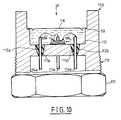
- FIG. 10 shows a possible mounting mode of a transducer according to the present invention.
- the transducer support consists of a piece of steel 109 which, with the exception of a thread 110 and a flat head 111 allowing it to be screwed, a flat transverse support surface 112 and a internal peripheral offset 113, is of substantially cylindrical shape.
- the transducer T is, on the side of the step, bonded by means of a flexible adhesive to the bearing surface 112, in which four bores 112a, 112b, 112c, 112d are made, two of which are visible in FIG. 10.
- a through electrical terminal, such as 114a, 114b, 114c is maintained in each of the bores by means of a glass bead such as 115a, 115b, which on the one hand ensures the attachment of each terminal with the bearing surface 112 , on the other hand the electrical insulation of this terminal and this surface, and finally a sealed closure of the bores 112a to 112d.
- each electrical terminal is connected to a pad such as 108c or 108d of the transducer T, the assembly being embedded in a volume of insulating oil closed by a deformable membrane of steel 116 welded to the recess 113.
- the part 109 thus designed can be screwed onto the wall of any enclosure in which there is a pressure P to be measured.
- the latter transmitted through the deformable membrane 116 to the volume of oil bathing the transducer, submits the latter to a hydrostatic pressure and a temperature which are measured by virtue of the resistance variations detected, at the terminals 114a to 114d outside the enclosure.
Landscapes
- Physics & Mathematics (AREA)
- General Physics & Mathematics (AREA)
- Engineering & Computer Science (AREA)
- Microelectronics & Electronic Packaging (AREA)
- Power Engineering (AREA)
- Ceramic Engineering (AREA)
- Condensed Matter Physics & Semiconductors (AREA)
- Computer Hardware Design (AREA)
- Measuring Fluid Pressure (AREA)
- Pressure Sensors (AREA)
Abstract
Description
La présente invention a pour objet un capteur de pression à semi-conducteur.The present invention relates to a semiconductor pressure sensor.
Selon un aspect, l'invention vise plus particulièrement, mais non exclusivement, un dispositif sensible à une pression hydrostatique à laquelle il est soumis, comprenant au moins une première couche d'arseniure de gallium-aluminium AlxGa1-xAs dont la teneur relative (x) en aluminium est inférieure à 0.25, et une seconde couche d'arseniure de gallium-aluminium AlyGa1-yAs dont la teneur relative (y) en aluminium est supérieure à (x) et comprise entre 0.15 et 1, et dans lequel se forme, à l'interface de ces deux couches, un canal de conduction dont la résistance électrique varie en fonction de la pression subie par ce dispositif.According to one aspect, the invention relates more particularly, but not exclusively, to a device sensitive to a hydrostatic pressure to which it is subjected, comprising at least a first layer of gallium-aluminum arsenide Al x Ga 1-x As whose relative aluminum content (x) is less than 0.25, and a second layer of gallium-aluminum arsenide Al y Ga 1-y As whose relative aluminum content (y) is greater than (x) and between 0.15 and 1, and in which is formed, at the interface of these two layers, a conduction channel whose electrical resistance varies as a function of the pressure undergone by this device.
La sensibilité à la pression de structures composées d'éléments semi-conducteurs des colonnes III et V du tableau de Mendeleiev est aujourd'hui connue.The sensitivity to pressure of structures composed of semiconductor elements from columns III and V of the Mendeleiev table is known today.
En particulier, des structures d'arseniure de gallium - aluminium sur un substrat d'arseniure de gallium ont déjà fait l'objet de plusieurs publications, et leur comportement en pression ou en température a notamment été décrit dans les articles suivants:
- "Pressure and compositional dependences of the Hall coefficient in AlyGa1-yAs and their significance", N.Lifshitz, A.Jayaraman, R.A.Logan, Physical Review B, Vol. 21, No 2, (5 Janvier 1980), pp.670 à 678;
- "The conduction band structure and deep levels in Ga1-yAlyAs alloys from a high pressure experiment", A.Saxena, J. Phys. C: Solid State Phys. 13, (1980), pp.4323 à 4334;
- "Comprehensive analysis of Si-doped AlyGa1-yAs (x=0 to 1); Theory and experiments", N.Chand, T.Henderson, J.Klem, W.T.Masselink, R.Fisher, The American Physical Society, Physical Review B, Vol.30, No 8, (15 octobre 1984), pp. 448I à 4492; et
- "Hydrostatic Pressure Control of the Carrier Density in GaAs/GaAlAs Heterostructures; role of the metastable deep levels", J.M.Mercy, C.Bousquet, J.L.Robert, A.Raymond et al., Surface Science 142, (1984), pp 298-305.In particular, gallium arsenide - aluminum structures on a gallium arsenide substrate have already been the subject of several publications, and their behavior in pressure or in temperature has been described in particular in the following articles:
- "Pressure and compositional dependences of the Hall coefficient in Al y Ga 1-y As and their significance", N. Lifshitz, A.Jayaraman, RALogan, Physical Review B, Vol. 21,
- "The conduction band structure and deep levels in Ga 1-y Al y As alloys from a high pressure experiment", A.Saxena, J. Phys. C: Solid State Phys. 13, (1980), pp. 4323 to 4334;
- "Comprehensive analysis of Si-doped Al y Ga 1-y As (x = 0 to 1); Theory and experiments", N.Chand, T.Henderson, J.Klem, WTMasselink, R.Fisher, The American Physical Society , Physical Review B, Vol.30,
- "Hydrostatic Pressure Control of the Carrier Density in GaAs / GaAlAs Heterostructures; role of the metastable deep levels", JMMercy, C.Bousquet, JLRobert, A.Raymond et al., Surface Science 142, (1984), pp 298-305 .
Une caractéristique des structures connues de cette famille est qu'une variation de pression déterminée conduit à une variation relative correspondante de la résistivité de leur couche sensible, qui est fixée une fois pour toutes par la nature du matériau utilisé. A température ambiante, la limite est de 45% par kilobar. Il en résulte que la résolution de telles structures, c'est-à-dire la plus petite valeur de variation de pression qu'elles sont susceptibles de détecter, est indissociablement liée à la plus petite variation relative décelable de la résistance de leur couche sensible.A characteristic of the known structures of this family is that a determined pressure variation leads to a corresponding relative variation in the resistivity of their sensitive layer, which is fixed once and for all by the nature of the material used. At room temperature, the limit is 45% per kilobar. As a result, the resolution of such structures, that is to say the smallest value of pressure variation that they are capable of detecting, is inextricably linked to the smallest detectable relative variation in the resistance of their sensitive layer. .
On connait par ailleurs des capteurs de pression à jauges de contrainte, utilisant la piézorésistivité, dans lesquels la résistance électrique de chaque jauge varie en fonction de la contrainte qu'elle subit par application de la pression.Pressure sensors with strain gauges are also known, using piezoresistivity, in which the electrical resistance of each gauge varies as a function of the stress which it undergoes by application of the pressure.
Il est possible, en choisissant judicieusement les paramètres de fabrication de ces capteurs, de réaliser des structures, en particulier des structures sensibles à la pression, capables de fonctionner dans des plages prédéterminées de conditions de mesure, par exemple dans une gamme préalablement choisie de température et de pression.It is possible, by judiciously choosing the manufacturing parameters of these sensors, to produce structures, in particular pressure-sensitive structures, capable of operating within predetermined ranges of measurement conditions, for example in a previously chosen temperature range. and pressure.
Cependant, ces structures sont le plus souvent fragiles, limitées dans leurs performances, et rendues complexes par le fait que les jauges, qui ne sont pas directement sensibles à la pression hydrostatique, doivent être associées à une conformation particulière du capteur, propre à convertir la pression hydrostatique à mesurer en une contrainte anisotrope à laquelle les jauges sont seulement sensibles.However, these structures are most often fragile, limited in their performance, and made complex by the fact that the gauges, which are not directly sensitive to hydrostatic pressure, must be associated with a particular conformation of the sensor, capable of converting the hydrostatic pressure to be measured in an anisotropic stress to which the gauges are only sensitive.
Ces artifices conduisent à l'apparition de nombreux problèmes, notamment de stabilité à long terme et d'hystérésis.These devices lead to the appearance of many problems, including long-term stability and hysteresis.
De plus, l'adaptation d'un tel capteur à des conditions moyennes de fonctionnement étant réalisée une fois pour toutes au moment de sa fabrication, un capteur de ce type n'est pas susceptible de s'adapter à plusieurs gammes différentes de conditions moyennes de fonctionnement.In addition, the adaptation of such a sensor to average operating conditions being carried out once and for all at the time of its manufacture, a sensor of this type is not capable of adapting to several different ranges of average conditions Operating.
Dans ce contexte, un des buts de la présente invention est de proposer un capteur de pression capable de s'adapter dynamiquement à différentes conditions moyennes de mesure et de présenter, pour chacune d'elles, une résolution susceptible d'être ajustée et de prendre des valeurs élevées.In this context, one of the aims of the present invention is to provide a pressure sensor capable of dynamically adapting to different average measurement conditions and to present, for each of them, a resolution capable of being adjusted and taking high values.
Dans ce but, selon le premier aspect, l'invention propose un dispositif, sensible à la pression hydrostatique, comprenant au moins une première couche d'arseniure de gallium-aluminium AlxGa1-xAs dont la teneur relative (x) en aluminium est inférieure à 0.25, et une seconde couche d'arseniure de gallium-aluminium AlyGa1-yAs dont la teneur relative (y) en aluminium est supérieure à (x) et comprise entre 0.15 et 1, et dans lequel se forme, à l'interface de ces deux couches, un canal de conduction dont la résistance électrique varie en fonction d'une pression subie par ce dispositif, ce dernier comprenant un transistor à effet de champ et à distribution électronique bidimensionnelle (TEGFET), comprenant un drain, une source et une grille.To this end, according to the first aspect, the invention provides a device, sensitive to hydrostatic pressure, comprising at least a first layer of gallium-aluminum arsenide Al x Ga 1-x As whose relative content (x) in aluminum is less than 0.25, and a second layer of gallium-aluminum arsenide Al y Ga 1-y As whose relative aluminum content (y) is greater than (x) and between 0.15 and 1, and in which forms, at the interface of these two layers, a conduction channel whose electrical resistance varies according to a pressure undergone by this device, the latter comprising a field effect transistor and two-dimensional electronic distribution (TEGFET), comprising a drain, a source and a grid.
La couche d'arseniure de gallium-aluminium AlyGa1-yAs est sélectivement dopée par des impuretés de la colonne IV A et/ou de la colonne VI A du tableau périodique, par exemple l'un au moins des éléments Si, Ge, Sn, S, Se, et Te, à une concentration totale, intégrée sur l'épaisseur de cette couche, qui est avantageusement comprise entre 10¹² et 10¹³ atomes par centimètre carré.The layer of gallium-aluminum arsenide Al y Ga 1-y As is selectively doped with impurities from column IV A and / or from column VI A of the periodic table, for example at least one of the elements Si, Ge, Sn, S, Se, and Te, at a total concentration, integrated over the thickness of this layer, which is advantageously between 10¹² and 10¹³ atoms per square centimeter.
L'invention selon ce premier aspect propose en outre un procédé pour mesurer une pression hydrostatique comprenant une première opération consistant à soumettre un capteur de pression à la pression à mesurer, une seconde opération consistant à recueillir un signal de réponse du capteur, et une troisième opération consistant à déduire de ce signal la valeur de cette pression hydrostatique grâce à une loi connue reliant ce signal à cette valeur, ce procédé étant essentiellement caracterisé en ce que les première et seconde opérations sont effectuées en utilisant un capteur qui comprend au moins un transistor à effet de champ et à distribution électronique bidimensionnelle (TEGFET), comportant un drain, une source et une grille.The invention according to this first aspect further provides a method for measuring a hydrostatic pressure comprising a first operation consisting in subjecting a pressure sensor to the pressure to be measured, a second operation consisting in collecting a response signal from the sensor, and a third operation consisting in deducing from this signal the value of this hydrostatic pressure by virtue of a known law connecting this signal to this value, this method being essentially characterized in that the first and second operations are carried out using a sensor which comprises at least one field effect transistor and two-dimensional electronic distribution (TEGFET), comprising a drain, a source and a grid.
Un dispositif pour mettre en oeuvre la seconde opération mentionnée peut comprendre des moyens pour maintenir constants les potentiels de grille, de drain et de source, et des moyens pour mesurer le courant circulant entre le drain et la source.A device for implementing the second mentioned operation may include means for keeping the gate, drain and source potentials constant, and means for measuring the current flowing between the drain and the source.
Cependant, cette seconde opération peut aussi être mise en oeuvre grâce à des moyens pour maintenir constants les potentiels de drain et de source, et à des moyens pour ajuster le potentiel de grille de façon à maintenir constant le courant circulant entre le drain et la source.However, this second operation can also be implemented by means to keep the drain and source potentials constant, and by means for adjusting the gate potential so as to keep the current flowing between the drain and the source constant. .
Par ces caractéristiques, le dispositif et le procédé de ce premier aspect de l'invention sont susceptibles de s'adapter parfaitement au cas où les conditions de mesure de la pression hydrostatique évoluent, notamment par variation de cette pression elle-même ou par variation de la température, au voisinage de conditions de mesure moyennes, le procédé comprenant alors une opération consistant à ajuster, pour ces conditions de mesure moyennes, le potentiel de grille à une valeur à peine supérieure à la tension de seuil du transistor, et la tension drain-source à une valeur supérieure à la différence entre la tension de grille et la tension de seuil, de telle sorte que le transistor fonctionne en régime de saturation.By these characteristics, the device and the method of this first aspect of the invention are capable of adapting perfectly to the case where the conditions for measuring the hydrostatic pressure change, in particular by variation of this pressure itself or by variation of the temperature, in the vicinity of average measurement conditions, the method then comprising an operation consisting in adjusting, for these average measurement conditions, the gate potential to a value barely greater than the threshold voltage of the transistor, and the drain voltage -source at a value greater than the difference between the gate voltage and the threshold voltage, so that the transistor operates in saturation mode.
Comme cela est bien connu de l'homme de l'art, la tension de seuil du transistor est la tension de grille pour laquelle le courant drain-source s'annule. Par "une valeur à peine supérieure à la tension de seuil", on entend ici une valeur excédant d'au plus 1 volt la tension de seuil.As is well known to those skilled in the art, the threshold voltage of the transistor is the gate voltage for which the drain-source current is canceled. By "a value barely higher than the threshold voltage" is meant here a value exceeding by more than 1 volt the threshold voltage.
Le procédé de ce premier aspect de l'invention peut en outre être mis en oeuvre sous une autre forme, dans laquelle la première opération consiste essentiellement à soumettre à la pression hydrostatique à mesurer un ensemble de transistors à effet de champ et à distribution électronique bidimensionnelle intégrés dans un montage, connu sous le nom d'oscillateur en anneau, réalisé par la connexion d'un nombre impair de portes élémentaires, elles-mêmes composées de transistors et de diodes Schottky réalisés sur un même substrat. La troisième opération consiste alors essentiellement à recueillir le signal produit par cet oscillateur, et dont la fréquence est représentative de la pression à mesurer.The method of this first aspect of the invention can also be implemented in another form, in which the first operation consists essentially in subjecting to the hydrostatic pressure to be measured a set of two-dimensional electronic field effect transistors with electronic distribution. integrated into a circuit, known as a ring oscillator, produced by the connection of an odd number of elementary gates, themselves composed of transistors and Schottky diodes produced on the same substrate. The third operation then essentially consists in collecting the signal produced by this oscillator, and the frequency of which is representative of the pressure to be measured.
Selon un second aspect, la présente invention concerne plus particulièrement, mais non exclusivement, un transducteur de pression hydrostatique, comprenant au moins une couche semi-conductrice sensible à la pression qui est constituée d'un alliage d'au moins trois éléments des colonnes III et V du tableau périodique et dont la résistance électrique, variant avec ladite pression, a une valeur représentative de cette dernière à température constante, cette couche sensible à la pression étant solidaire d'un substrat constitué d'un alliage de deux desdits trois éléments et obtenue par épitaxie.According to a second aspect, the present invention relates more particularly, but not exclusively, to a hydrostatic pressure transducer, comprising at least one pressure-sensitive semiconductor layer which consists of an alloy of at least three elements from columns III and V of the periodic table and whose electrical resistance, varying with said pressure, has a value representative of the latter at constant temperature, this pressure-sensitive layer being integral with a substrate made of an alloy of two of said three elements and obtained by epitaxy.
Les capteurs de pression à base de semi-conducteurs sont utilisés depuis une vingtaine d'années. Ils font habituellement appel à une structure comportant quatre jauges de silicium disposées en pont de Wheatstone, dopées intentionnellement par des impuretés acceptrices, de telle sorte qu'elles présentent une conductivité de type p, lesdites jauges étant réalisées par diffusion ou implantation des impuretés dans un substrat de silicium de conductivité de type n.Pressure sensors based on semiconductors have been used for about twenty years. They usually use a structure comprising four silicon gauges arranged in a Wheatstone bridge, intentionally doped with acceptor impurities, so that they have a p-type conductivity, said gauges being produced by diffusion or implantation of the impurities in a n type conductivity silicon substrate.
L'effet utilisé est la piézorésistivité, qui se manifeste par le fait que la résistance électrique de chaque jauge varie en fonction de la contrainte qu'elle subit par application de la pression.The effect used is piezoresistivity, which manifests itself in the fact that the electrical resistance of each gauge varies according to the stress which it undergoes by application of the pressure.
Comme la résistivité du silicium n'est sensible qu'à des contraintes uniaxiales ou biaxiales, et non pas directement à la pression hydrostatique, les capteurs de ce type sont conçus de façon que l'application d'une pression hydrostatique se traduise par l'apparition de telles contraintes. Pour cela, ces capteurs comportent une membrane réalisée par gravure d'une de leurs faces, qui est mise à une pression de référence, tandis que l'autre face, qui supporte les jauges de contrainte, est mise à la pression hydrostatique à mesurer, de manière qu'apparaisse sur cette face un système de contraintes principalement dirigées selon le plan de la membrane.Since the resistivity of silicon is sensitive only to uniaxial or biaxial constraints, and not directly to hydrostatic pressure, sensors of this type are designed so that the application of hydrostatic pressure results in appearance of such constraints. For this, these sensors comprise a membrane produced by etching one of their faces, which is brought to a reference pressure, while the other face, which supports the strain gauges, is brought to the hydrostatic pressure to be measured, of so that appears on this face a system of stresses mainly directed along the plane of the membrane.
Grâce à un choix judicieux de l'emplacement des jauges par rapport à ce système de contraintes, la résistance de deux des jauges du pont augmente avec la pression appliquée, tandis que la résistance des deux autres diminue. pont de Wheatstone est alors déséquilibré et un signal dépendant de la pression peut ainsi etre obtenu.Thanks to a judicious choice of the location of the gauges in relation to this constraint system, the resistance of two of the bridge gauges increases with the pressure applied, while the resistance of the other two decreases. Wheatstone bridge is then unbalanced and a pressure dependent signal can be obtained.
Pour réaliser, avec un tel capteur, un transducteur de pression absolue, l'élément sensible en silicium doit être scellé sous pression nulle, par exemple par un verre de type Pyrex.To produce, with such a sensor, an absolute pressure transducer, the sensitive silicon element must be sealed under zero pressure, for example by a glass of Pyrex type.
Bien que leurs propriétés soient assez satisfaisantes dans de nombreuses applications, ces capteurs présentent cependant quelques limitations qui en gênent l'utilisation dans des cas particuliers, éventuellement importants.Although their properties are quite satisfactory in many applications, these sensors however have certain limitations which hinder their use in particular, possibly important, cases.
En particulier, non seulement le signal délivré par les capteurs de ce type est intrinsèquement représentatif à la fois de la pression et de la température, mais surtout une correction en température de ce signal représentatif de la pression et de la température s'est toujours avérée extrêmement délicate.In particular, not only is the signal delivered by sensors of this type intrinsically representative of both pressure and temperature, but above all a correction in temperature of this signal representative of pressure and temperature has always been found to be extremely delicate.
En effet, dans le meilleur des cas, une telle correction est réalisée grâce à une sonde de température disposée sur la même face que les jauges, mais en dehors de la membrane pour ne pas subir les contraintes liées à la pression; or, en raison de la structure hétérogène du capteur et du fait que la sonde de température ne se situe pas dans le même environnement que les jauges, la constante de temps de mise en équilibre thermique de la sonde en cas de variation de température, et/ou la variation des effets de relaxation mécanique consécutifs à une dilatation, dont la constante de temps est de l'ordre de une minute à une heure, ne sont jamais les memes pour la sonde et pour les jauges, de sorte que le signal représentatif de la pression ne peut pas être efficacement corrigé dans les cas où la pression et/ou la température varient rapidement.Indeed, in the best of cases, such a correction is carried out thanks to a temperature probe arranged on the same face as the gauges, but outside the membrane so as not to undergo the pressure constraints; however, due to the heterogeneous structure of the sensor and the fact that the temperature probe is not located in the same environment as the gauges, the time constant for thermal equilibrium of the probe in the event of temperature variation, and / or the variation in the effects of mechanical relaxation following expansion, whose time constant is of the order of one minute to one hour, are never the same for the probe and for the gauges, so that the representative signal pressure cannot be effectively corrected in cases where pressure and / or temperature change rapidly.
De façon plus générale, ces capteurs connus font apparaître tous les problèmes inhérents à une structure composite, notamment des problèmes de stabilité à long terme et d'hystérésis.More generally, these known sensors reveal all the problems inherent in a composite structure, in particular problems of long-term stability and hysteresis.
On connait par ailleurs des matériaux semi-conducteurs présentant une bonne sensibilité à la pression hydrostatique, propres à fournir un signal de réponse fonction de cette pression sans le recours à des structures complexes propres à la convertir en des contraintes uniaxiales ou biaxiales.There are also known semiconductor materials having good sensitivity to hydrostatic pressure, capable of providing a response signal which is a function of this pressure without the use of complex structures capable of converting it into uniaxial or biaxial constraints.
De nombreux matériaux de ce type ont été récemment étudiés, leur comportement en pression n'étant le plus souvent observé qu'en vue de la mise en évidence d'autres propriétés utilisables dans d'autres secteurs de la technique, comme la micro-électronique ou l'opto-électronique.Many materials of this type have been recently studied, their behavior under pressure being most often observed only with a view to demonstrating other properties which can be used in other fields of technology, such as microelectronics or opto-electronics.
Parmi ces matériaux figurent notamment les semi-conducteurs indium - antimoine, gallium - antimoine, aluminium - arsenic, indium - phosphore, arsenic - gallium, arsenic - indium, et leurs mélanges, dopés de type n par un élément des colonnes IV ou VI, en particulier par du silicium, de l'étain, du tellure, du soufre ou du sélénium.Among these materials are in particular the indium - antimony, gallium - antimony, aluminum - arsenic, indium - phosphorus, arsenic - gallium, arsenic - indium semiconductors, and their mixtures, n-doped by an element from columns IV or VI, in particular by silicon, tin, tellurium, sulfur or selenium.
En particulier, l'arseniure de gallium - aluminium a fait l'objet de plusieurs publications, notamment les trois publications mentionnées ci-dessus.In particular, gallium arsenide - aluminum has been the subject of several publications, in particular the three publications mentioned above.
Si ces matériaux manifestent une sensibilité assez élevée à la pression hydrostatique, ils montrent aussi une sensibilité à la température qui, selon les alliages considérés et la valeur du dopage, peut être très importante.If these materials show a fairly high sensitivity to hydrostatic pressure, they also show a sensitivity to temperature which, depending on the alloys considered and the value of doping, can be very important.
Ce problème d'une dépendance en température du signal de sortie supposé représenter la pression se pose même, avec des matériaux de ce type, de façon a priori tellement plus aigüe que dans le cas des capteurs à jauges piézorésistives de silicium que l'homme de l'art est naturellement conduit à écarter leur emploi pour la réalisation industrielle de capteurs de pression susceptibles d'être soumis à des variations rapides ou importantes de la température.This problem of a dependence in temperature of the output signal supposed to represent the pressure arises even, with materials of this type, in a priori so much more acute than in the case of the sensors with piezoresistive gauges of silicon that the man of the art is naturally led to discard their use for the industrial production of pressure sensors capable of being subjected to rapid or significant variations in temperature.
Dans ce contexte cependant, le second aspect de l'invention propose un moyen simple de compensation, en fonction de la température, du signal de sortie d'un capteur de pression hydrostatique comprenant un alliage d'au moins trois éléments des colonnes III et V du tableau périodique, permettant de tirer parti, même dans un milieu industriel, des avantages que présentent ces matériaux dans leur application aux capteurs de pression hydrostatique.In this context, however, the second aspect of the invention provides a simple means of compensating, as a function of temperature, for the output signal of a hydrostatic pressure sensor comprising an alloy of at least three elements from columns III and V the periodic table, allowing you to take advantage, even in an industrial environment, of the advantages these materials in their application to hydrostatic pressure sensors.
L'invention selon ce second aspect repose sur la mise en évidence du fait que les limitations qui s'appliquent aux sondes thermiques dans le cas des capteurs à jauges piézorésistives de silicium ne s'appliquent pas dans le cas des capteurs directement sensibles à la pression hydrostatique, du type précédemment mentionné, en raison de la structure homogène de ces derniers.The invention according to this second aspect is based on the fact that the limitations which apply to thermal probes in the case of sensors with piezoresistive silicon gauges do not apply in the case of sensors directly sensitive to pressure hydrostatic, of the type previously mentioned, due to the homogeneous structure of the latter.
Un transducteur de pression hydrostatique conforme à ce second aspect de l'invention, qui comprend au moins une couche semi-conductrice sensible à la pression, constituée d'un alliage d'au moins trois éléments des colonnes III et V du tableau périodique et dont la résistance électrique, variant avec ladite pression, a une valeur représentative de cette dernière à température constante, cette couche sensible à la pression étant solidaire d'un substrat constitué d'un alliage d'au moins deux desdits trois éléments et obtenue par épitaxie, comprend en outre un capteur de température, supporté par le même substrat et susceptible de fournir un signal représentatif de la température de ce dernier.A hydrostatic pressure transducer according to this second aspect of the invention, which comprises at least one pressure-sensitive semiconductor layer, consisting of an alloy of at least three elements from columns III and V of the periodic table and of which the electrical resistance, varying with said pressure, has a value representative of the latter at constant temperature, this pressure-sensitive layer being integral with a substrate made of an alloy of at least two of said three elements and obtained by epitaxy, further includes a temperature sensor, supported by the same substrate and capable of providing a signal representative of the temperature of the latter.
Dans une forme de réalisation préférée du transducteur selon ce second aspect de l'invention, la couche sensible à la pression est constituée d'arseniure de gallium-aluminium AlxGa1-xAs dont la teneur relative (x) en aluminium est comprise entre 0.25 et 0.40, et le substrat est constitué d'arseniure de gallium.In a preferred embodiment of the transducer according to this second aspect of the invention, the pressure-sensitive layer consists of gallium-aluminum arsenide Al x Ga 1-x As whose relative aluminum content (x) is included between 0.25 and 0.40, and the substrate consists of gallium arsenide.
Plus avantageusement encore, la teneur relative (x) en aluminium de la couche sensible à la pression est comprise entre 0.27 et 0.37, et a une valeur optimale comprise entre 0.29 et 0.35, et plus précisément encore entre 0.32 et 0.33.Even more advantageously, the relative aluminum content (x) of the pressure-sensitive layer is between 0.27 and 0.37, and has an optimal value between 0.29 and 0.35, and more precisely still between 0.32 and 0.33.
De préférence, cette couche sensible à la pression est dopée par des impuretés de la colonne IV A et/ou de la colonne VI A du tableau périodique, plus particulièrement les éléments Si, Ge, Sn, S, Se, et Te, à une concentration totale comprise entre 2.10¹⁷ et 10²⁰ atomes par centimètre cube.Preferably, this pressure-sensitive layer is doped with impurities from column IV A and / or from column VI A of the periodic table, more particularly the elements Si, Ge, Sn, S, Se, and Te, to a total concentration between 2.10¹⁷ and 10²⁰ atoms per cubic centimeter.
Pour optimiser les corrections de température, il est avantageux que le capteur de température soit lui-même essentiellement constitué d'une couche semi-conductrice sensible à la température qui présente une distribution tridimensionnelle d'électrons, qui est constituée d'un alliage des mêmes éléments que ceux de la couche sensible à la pression, et dont la résistance électrique, variant avec la température du substrat, a une valeur représentative de cette dernière à pression constante, cette couche sensible à la température étant également obtenue par épitaxie.To optimize the temperature corrections, it is advantageous that the temperature sensor itself is essentially constituted by a semiconductor layer sensitive to temperature which has a three-dimensional distribution of electrons, which consists of an alloy of the same elements than those of the pressure-sensitive layer, and whose electrical resistance, varying with the temperature of the substrate, has a value representative of the latter at constant pressure, this temperature-sensitive layer also being obtained by epitaxy.
Dans le cas où la couche sensible à la pression est constituée d'arseniure de gallium-aluminium, la couche sensible à la température est de préférence également constituée d'arseniure de gallium-aluminium AlyGa1-yAs, avec une teneur relative (y) en aluminium comprise entre 0 et 0.25 ou entre 0.45 et 1.In the case where the pressure-sensitive layer consists of gallium-aluminum arsenide, the temperature-sensitive layer preferably also consists of gallium-aluminum arsenide Al y Ga 1-y As, with a relative content (y) aluminum between 0 and 0.25 or between 0.45 and 1.
Dans ce cas, lesdites couches sensibles à la pression et à la température peuvent être empilées l'une sur l'autre et séparées par une couche d'isolation.In this case, said pressure and temperature sensitive layers can be stacked on top of each other and separated by an insulation layer.
Cette couche d'isolation est de préférence non dopée, formée par épitaxie, constituée d'arseniure de gallium-aluminium AlzGa1-zAs dont la teneur relative (z) en aluminium est comprise entre 0.40 et 0.50, et séparée du substrat au moins par la couche sensible à la pression.This insulation layer is preferably undoped, formed by epitaxy, consisting of gallium-aluminum arsenide Al z Ga 1-z As whose relative aluminum content (z) is between 0.40 and 0.50, and separated from the substrate. at least by the pressure-sensitive layer.
Selon un mode de réalisation, le transducteur de ce second aspect de l'invention comprend une première zone dans laquelle les couches sensibles et d'isolation sont empilées les unes sur les autres, et une seconde zone, latéralement déplacée par rapport à la première, dans laquelle au moins la couche sensible supérieure a au moins été partiellement ôtée; il comprend en outre une première paire de contacts métalliques établis dans la première zone, séparés l'un de l'autre par une première distance, et une seconde paire de contacts métalliques établis dans la seconde zone, séparés l'un de l'autre par une seconde distance.According to one embodiment, the transducer of this second aspect of the invention comprises a first zone in which the sensitive and insulating layers are stacked on each other, and a second zone, laterally displaced relative to the first, in which at least the upper sensitive layer has at least been partially removed; it further comprises a first pair of metallic contacts established in the first zone, separated from each other by a first distance, and a second pair of metallic contacts established in the second zone, separated from each other by a second distance.
La première distance est avantageusement inférieure au double de la quantité représentée par la racine carrée de: rho₀.e₀/((rho₁/e₁)+(rho₂/e₂)), dans laquelle rho₀, rho₁ et rho₂ sont les résistivités respectives de la couche d'isolation, de la couche sensible la plus éloignée du substrat, et de la couche la plus proche du substrat, et dans laquelle e₀, e₁, et e₂ sont les épaisseurs respectives de la couche d'isolation, de la couche sensible la plus eloignée du substrat, et de la couche la plus proche du substrat. De préférence, la seconde distance est alors supérieure à cette même quantité.The first distance is advantageously less than twice the quantity represented by the square root of: rho₀.e₀ / ((rho₁ / e₁) + (rho₂ / e₂)), in which rho₀, rho₁ and rho₂ are the respective resistivities of the layer of insulation, of the sensitive layer furthest from the substrate, and of the layer closest to the substrate, and in which e₀, e₁, and e₂ are the respective thicknesses of the insulation layer, of the most sensitive layer away from the substrate, and the layer closest to the substrate. Preferably, the second distance is then greater than this same amount.
D'autres caractéristiques et avantages de l'invention ressortiront clairement de la description qui en faite ci-après, à titre indicatif et nullement limitatif, en référence aux dessins annexés, parmi lesquels:
- - la figure 1 est une vue en coupe d'un transistor TEGFET utilisable dans le cadre de la présente invention;
- - la figure 2 est une vue en coupe d'un montage utilisant les principes de la présente invention;
- - la figure 3 est un diagramme représentant la variation du courant drain-source d'un transistor TEGFET en fonction de la tension de grille appliquée à ce dernier;
- - la figure 4 est un diagramme représentant les variations du courant drain-source du canal d'un transistor TEGFET en fonction d'une part de la tension de grille appliquée à ce dernier et d'autre part de la pression hydrostatique à laquelle il est soumis;
- - la figure 5 est un agrandissement d'une partie de la figure 4;
- - la figure 6 est un schéma d'un dispositif utilisant une première technique de mesure de la pression; et
- - la figure 7 est un schéma d'un dispositif utilisant une seconde technique de mesure de la pression;
- - la figure 8 est une vue en coupe d'un transducteur conforme à l'invention, faite suivant la ligne I-I de la figure 9;
- - la figure 9 est une vue en plan d'un transducteur conforme à l'invention;
- - la figure 10 est une vue en coupe d'un montage utilisant un transducteur conforme à l'invention.
- - Figure 1 is a sectional view of a TEGFET transistor usable in the context of the present invention;
- - Figure 2 is a sectional view of an assembly using the principles of the present invention;
- - Figure 3 is a diagram showing the variation of the drain-source current of a TEGFET transistor as a function of the gate voltage applied to the latter;
- FIG. 4 is a diagram representing the variations in the drain-source current of the channel of a TEGFET transistor as a function of the hand of the gate voltage applied to the latter and on the other hand of the hydrostatic pressure at which it is submitted;
- - Figure 5 is an enlargement of part of Figure 4;
- - Figure 6 is a diagram of a device using a first pressure measurement technique; and
- - Figure 7 is a diagram of a device using a second pressure measurement technique;
- - Figure 8 is a sectional view of a transducer according to the invention, taken along line II of Figure 9;
- - Figure 9 is a plan view of a transducer according to the invention;
- - Figure 10 is a sectional view of an assembly using a transducer according to the invention.
Les transistors TEGFET, tels que celui représenté sur la figure 1, sont connus dans le domaine de l'électronique rapide. Ils tirent leur désignation d'une abréviation de leur définition en langue anglaise, "Two-dimensional Electron Gas Field Effect Transistor", c'est-à-dire transistor à effet de champ et à distribution électronique bidimensionnelle.TEGFET transistors, such as that shown in Figure 1, are known in the field of fast electronics. They derive their designation from an abbreviation of their definition in English, "Two-dimensional Electron Gas Field Effect Transistor", that is to say transistor with field effect and two-dimensional electronic distribution.
Ils peuvent être produits, par exemple, par le procédé décrit dans l'article dans l'article "Growth of extremely uniform layers by rotating substrate holder with molecular beam epitaxy for applications to electro-optic and microwave devices", A.Y.Cho et K.Y.Cheng, Appl. Phys. Lett. 38(5), 1 Mars 1981, pp. 360 à 362.They can be produced, for example, by the process described in the article in the article "Growth of extremely uniform layers by rotating substrate holder with molecular beam epitaxy for applications to electro-optic and microwave devices", AYCho and KYCheng , Appl. Phys. Lett. 38 (5), March 1, 1981, pp. 360 to 362.
La structure du TEGFET 1 de la figure 1 est plus précisément la suivante.The structure of
Le substrat 2 est formé d'une plaquette d'arseniure de gallium GaAs semi-isolant, d'une épaisseur de l'ordre de 300 micromètres par exemple.The
Sur ce substrat est déposée par épitaxie une couche 3 d'arseniure de gallium GaAs non dopé, d'une épaisseur de 1 à quelques micromètres, constituant une couche tampon destinée à offrir un bon état de surface aux couches ultérieures.On this substrate is deposited by epitaxy a layer 3 of gallop arsenide GaAs undoped, with a thickness of 1 to a few micrometers, constituting a buffer layer intended to offer a good surface condition to the subsequent layers.
Sur cette couche tampon 3 peut être déposée par épitaxie une couche supplémentaire (non représentée), en arseniure de gallium-aluminium AlxGa1-xAs non dopé, dont la teneur relative (x) en aluminium est inférieure à 0.25 et dont l'épaisseur est par exemple de l'ordre de quelques dixièmes de micromètre. Globalement, la couche tampon 3, recouverte ou non de cette couche supplémentaire, constitue donc une couche d'arseniure de gallium-aluminium AlxGa1-xAs non dopé, dont la teneur relative (x) en aluminium, éventuellement nulle, est inférieure à 0.25.On this buffer layer 3 can be deposited by epitaxy an additional layer (not shown), of gallium-aluminum arsenide Al x Ga 1-x As undoped, whose relative aluminum content (x) is less than 0.25 and whose l thickness is for example of the order of a few tenths of a micrometer. Overall, the buffer layer 3, whether or not covered with this additional layer, therefore constitutes a layer of gallium-aluminum arsenide Al x Ga 1-x As undoped, the relative aluminum content (x) of which is possibly zero. less than 0.25.
Sur la couche tampon 3 ou sur cette couche supplémentaire optionnelle non représentée, est déposée, également par épitaxie, une couche de séparation 4 en arseniure de gallium-aluminium AlyGa1-yAs non dopé, dont la teneur relative (y) en aluminium est supérieure à (x) et comprise entre 0.15 et 1. L'épaisseur de cette couche de séparation 4 est par exemple de l'ordre de 0 à 30 nanomètres.On the buffer layer 3 or on this optional additional layer, not shown, is deposited, also by epitaxy, a
Sur la couche de séparation 4 est ensuite déposée, toujours par épitaxie, une couche 5 en arseniure de gallium-aluminium AlyGa1-yAs dopé, dont la teneur relative (y) en aluminium est sensiblement la même que celle de la couche de séparation 4, et dont l'épaisseur est par exemple comprise entre 30 et 100 nanomètres.Next on the
La couche 5 peut être dopée par des impuretés de la colonne IV A et/ou de la colonne VI A du tableau périodique, notamment par l'un au moins des éléments Si, Ge, Sn, S, Se, et Te, à une concentration totale, intégrée sur l'épaisseur de cette couche, comprise entre 10¹² et 10¹³ atomes par centimètre carré.
Comme le montre symboliquement, par des tirets, la figure 1, un gaz d'électrons bidimensionnel apparaît à l'interface que forment les couches 4 et 5 d'arseniure de gallium-aluminium AlyGa1-yAs avec la couche 3, et sa couche supplémentaire éventuelle, en arseniure de gallium-aluminium AlxGa1-xAs.As symbolically shown, by dashes in FIG. 1, a two-dimensional electron gas appears at the interface formed by
La couche 5 est, de façon connue, recouverte d'une couche de reprise de contact en arseniure de gallium GaAs, puis gravée pour présenter une dépression centrale 5a, après quoi des plots métalliques 6a, 6b, 6c, destinés à constituer respectivement le drain, la grille, et la source du transistor, sont déposés.
La figure 2 représente un mode de montage possible du transistor TEGFET en tant que capteur de pression hydrostatique.FIG. 2 represents a possible mounting mode of the TEGFET transistor as a hydrostatic pressure sensor.
Le support du transistor 1 est constitué par une pièce d'acier 7 qui, à l'exception d'un filetage 8 et d'une tête à méplats 9 permettant son vissage, d'une surface transversale plane d'appui lo et d'un décrochement périphérique interne est de forme sensiblement cylindrique.The support of the
Le transducteur 1 est, du coté du décrochement, collé au moyen d'une colle souple sur la surface d'appui 10, dans laquelle sont pratiqués trois alésages 10a, 10b, 10c, dont deux sont visibles sur la figure 2.The
Une borne électrique traversante, telle que 12a, 12b, 12c est maintenue dans chacun des alésages au moyen d'une perle de verre telle que 13a, 13b, 13c, qui assure d'une part la solidarisation de chaque borne avec la surface d'appui 10, d'autre part l'isolation électrique de cette borne et de cette surface, et enfin une obturation étanche des alésages 10a à 10c.A through electrical terminal, such as 12a, 12b, 12c is maintained in each of the bores by means of a glass bead such as 13a, 13b, 13c, which ensures on the one hand the solidification of each terminal with the surface of
Du côté du décrochement 11, chaque borne électrique est connectée à un plot tel que 6a, 6b, ou 6c du transistor 1, l'ensemble étant noyé dans un volume d'huile isolante fermé par une membrane déformable en acier 14 soudée sur le décrochement 11.On the side of the
La pièce 7 ainsi con ue peut être vissée sur la paroi de toute enceinte dans laquelle règne une pression P à mesurer. Cette dernière, transmise à travers la membrane déformable 14 au volume d'huile baignant le transistor, soumet ce dernier à des conditions de pression hydrostatique et de température qu'il est possible, conformément à l'enseignement de l'invention, de mesurer de manière optimale de la façon décrite ci-après en référence aux figures 3 et 4.The part 7 thus designed can be screwed onto the wall of any enclosure in which there is a pressure P to be measured. The latter, transmitted through the
La figure 3 représente la variation du courant IDS circulant entre le drain et la source d'un TEGFET en fonction de la tension VG appliquée sur sa grille, la tension VDS appliquée entre le drain et la source du transistor étant constante.FIG. 3 represents the variation of the current I DS flowing between the drain and the source of a TEGFET as a function of the voltage V G applied to its gate, the voltage V DS applied between the drain and the source of the transistor being constant.
Cette figure fait apparaître une première zone Z1, dite zone de blocage, correspondant aux valeurs de la tension de grille VG pour lesquelles aucun courant IDS ne circule dans le transistor.This figure shows a first zone Z1, called blocking zone, corresponding to the values of the gate voltage V G for which no current I DS flows in the transistor.
Une seconde zone Z2, dite zone de régime de saturation, apparaît pour des valeurs de la tension de grille supérieures à une valeur limite VT, dite valeur de seuil, mais inférieures à la valeur de la tension de grille VL au delà de laquelle commence une troisième zone Z3, dite zone de régime linéaire, caractérisée par une loi affine de variation du courant IDS en fonction de la tension VG.A second zone Z2, called the saturation regime zone, appears for values of the gate voltage greater than a limit value V T , called the threshold value, but less than the value of the gate voltage V L beyond which begins a third zone Z3, called the linear regime zone, characterized by an affine law of variation of the current I DS as a function of the voltage V G.
La figure 4 représente également la variation du courant drain-source IDS en fonction de la tension VG appliquée sur la grille pour une valeur constante de la polarisation VDS, mais pour deux valeurs distinctes d'une pression hydrostatique P appliquée sur le transistor.FIG. 4 also represents the variation of the drain-source current I DS as a function of the voltage V G applied to the gate for a constant value of the polarization V DS , but for two distinct values of a hydrostatic pressure P applied to the transistor .
Cette figure met immédiatement en évidence le fait que le courant IDS diminue lorsque la pression P appliquée augmente, phénomène dont l'exploitation optimale est à la base de l'invention.This figure immediately highlights the fact that the current I DS decreases when the pressure P applied increases, a phenomenon whose optimal exploitation is the basis of the invention.
La valeur du courant IDS, mesurée en conservant la polarisation du transistor 1 soumis à la pression, c'est-à-dire en maintenant constants les potentiels de grille, de drain et de source de ce transistor, est en effet utilisable comme signal représentatif de la pression P.The value of the current I DS , measured by preserving the polarization of the
Cette technique de mesure est illustrée par la droite verticale DV de la figure 4, qui, à deux valeurs différentes de la pression, fait correspondre de façon univoque deux valeurs différentes du courant IDS.This measurement technique is illustrated by the vertical line DV of FIG. 4, which, at two different values of the pressure, unequivocally corresponds two different values of the current I DS .
Un dispositif pour la mise en oeuvre de cette technique est représenté sur la figure 6. Outre le transistor 1, ce dispositif comprend une source de tension réglable 15 propre à fournir un potentiel de drain VD constant mais réglable, une source de tension réglable 16 propre à fournir un potentiel de grille VG constant mais réglable, et un ampèremètre 17 indiquant la valeur du courant IDS. La source est également reliée à un potentiel constant, par exemple celui de la masse.A device for implementing this technique is shown in FIG. 6. In addition to the
Cependant, comme le montre la figure 4, une autre technique de mesure est également possible puisqu'en effet la valeur à laquelle il faut ajuster le potentiel de grille VG de façon à maintenir constant le courant IDS, en maintenant constants les potentiels de drain et de source, est aussi représentative de la pression hydrostatique à laquelle est soumis le transistor.However, as shown in FIG. 4, another measurement technique is also possible since in fact the value to which the gate potential V G must be adjusted so as to keep the current I DS constant, while keeping the potentials constant. drain and source, is also representative of the hydrostatic pressure to which the transistor is subjected.
Cette seconde technique de mesure est illustrée par la droite horizontale DH de la figure 4 qui, à deux valeurs différentes de la pression, fait correspondre de façon univoque deux valeurs différentes de la tension de grille VG pour une même valeur du courant IDS.This second measurement technique is illustrated by the horizontal line DH of FIG. 4 which, at two different values of the pressure, unequivocally corresponds two different values of the gate voltage V G for the same value of the current I DS .
Un dispositif pour la mise en oeuvre de cette seconde technique est représenté sur la figure 7. Outre le transistor 1, ce dispositif comprend une source de tension réglable 18 propre à fournir un potentiel de drain VD constant mais réglable, une résistance de valeur R, connectée entre la source du transistor et la masse, et traversée par le courant IDS, une source de tension réglable 19 propre à fournir un potentiel de référence égal au produit R.IDS, un amplificateur différentiel 20 dont les entrées sont connectées à la source du transistor 1 et à la source de tension 19, et dont la sortie est connectée à la grille de ce transistor, et un voltmètre 21 indiquant la valeur du potentiel VG.A device for implementing this second technique is shown in FIG. 7. In addition to
Dans un tel montage, l'amplificateur 20 ajuste le potentiel de grille de façon que la tension aux bornes de la résistance R soit constante, ce qui fixe d'une part la valeur du potentiel de la source du transistor 1, et d'autre part la valeur du courant IDS.In such an arrangement, the
Un premier avantage, considérable, de l'utilisation d'un TEGFET comparée à l'utilisation d'un composant passif tel que l'hétérostructure dépourvue de grille décrite dans l'article "Hydrostatic Pressure Control of the Carrier Density in GaAs/GaAlAs Heterostructures; role of the metastable deep levels", précédemment cité, et qui est directement obtenu par la mise en oeuvre de l'une ou l'autre des deux techniques de mesure décrites en référence à la figure 4, réside dans le fait que le contrôle du potentiel de grille, qu'il est important de ne pas rendre flottant, assure une bonne immunité aux parasites en écrantant toute influence électrostatique du milieu extérieur sur le canal de conduction sensible à la pression.A first, considerable advantage of the use of a TEGFET compared to the use of a passive component such as the heterostructure without grid described in the article "Hydrostatic Pressure Control of the Carrier Density in GaAs / GaAlAs Heterostructures ; role of the metastable deep levels ", previously cited, which is directly obtained by the implementation of one or the other of the two measurement techniques described with reference to FIG. 4, resides in the fact that the control the gate potential, which it is important not to make floating, ensures good immunity to parasites by shielding any electrostatic influence from the external medium on the conduction channel sensitive to pressure.
Un second avantage résultant de l'utilisation d'un TEGFET comparée à l'utilisation d'un transistor différent, d'un MOSFET par exemple, réside dans le fait que le TEGFET est directement sensible à la pression hydrostatique, de sorte que les structures à la fois complexes, fragiles et limitées dans leurs performances notamment par les problèmes de stabilité à long terme et d'hystérésis qu'elles font apparaître, mais qui doivent néanmoins être utilisées pour convertir une pression hydrostatique à mesurer en une contrainte à laquelle le capteur est seulement sensible, deviennent inutiles.A second advantage resulting from the use of a TEGFET compared to the use of a different transistor, of a MOSFET for example, lies in the fact that TEGFET is directly sensitive to hydrostatic pressure, so that the structures both complex, fragile and limited in their performance, in particular by the problems of long-term stability and hysteresis which they reveal, but which must nevertheless be used to convert a hydrostatic pressure to be measured into a stress at which the sensor is only sensitive, become useless.
Cependant, l'utilisation d'un TEGFET, comparée à l'utilisation d'un capteur passif, conduit encore à un autre avantage, s'il est employé conformément à l'invention, selon la procédure suivante.However, the use of a TEGFET, compared to the use of a passive sensor, leads to yet another advantage, if it is used according to the invention, according to the following procedure.
Comme le montre la figure 4, la variation relative du courant IDS est maximale aux valeurs les plus négatives de la tension de grille, c'est-à-dire dans la zone Z2 de régime de saturation. Par exemple, la variation relative du courant IDS pour une variation absolue de 1 kbar de la pression, est de l'ordre de 14% lorsque le transistor fonctionne en régime linéaire (zone Z3), pour une valeur de VG voisine de -0.5 volts, alors qu'elle peut être supérieure à 50% lorsque le transistor fonctionne en régime de saturation, c'est-à-dire avec une tension de grille à peine supérieure à la valeur de seuil VT.As shown in FIG. 4, the relative variation of the current I DS is maximum at the most negative values of the gate voltage, that is to say in the zone Z2 of saturation regime. For example, the relative variation of the current I DS for an absolute variation of 1 kbar of the pressure, is of the order of 14% when the transistor operates in linear mode (zone Z3), for a value of V G close to - 0.5 volts, whereas it can be greater than 50% when the transistor is operating in saturation mode, that is to say with a gate voltage barely greater than the threshold value V T.
Ainsi, puisque le réglage de la tension de grille permet un déplacement du point de mesure le long de chacune des courbes de la figure 4, il est possible d'adapter dynamiquement le capteur TEGFET au domaine de pression dans lequel il travaille et même, dans la mesure où chaque courbe peut éventuellement varier en fonction d'autres paramètres physiques, par exemple la température, il est possible d'adapter le capteur TEGFET à son environnement de mesure tout entier.Thus, since the adjustment of the gate voltage allows a displacement of the measurement point along each of the curves of FIG. 4, it is possible to dynamically adapt the TEGFET sensor to the pressure range in which it works and even, insofar as each curve may possibly vary as a function of other physical parameters, for example the temperature, it is possible to adapt the TEGFET sensor to its entire measurement environment.
En particulier, dans le cas où les conditions de mesure de la pression hydrostatique évoluent, notamment par variation de cette pression elle-même ou par variation de la température, au voisinage de conditions de mesure moyennes, il est avantageux d'ajuster, pour ces conditions de mesure moyennes, le potentiel de grille à une valeur à peine supérieure à la tension de seuil du transistor, et la tension drain-source à une valeur supérieure à la différence entre la tension de grille et la tension de seuil, de telle sorte que le transistor fonctionne en régime de saturation.In particular, in the case where the conditions for measuring the hydrostatic pressure change, in particular by variation of this pressure itself or by variation of the temperature, in the vicinity of average measurement conditions, it is advantageous to adjust, for these average measurement conditions, the gate potential at a value barely greater than the threshold voltage of the transistor, and the drain-source voltage at a value greater than the difference between the gate voltage and the threshold voltage, so that the transistor operates in saturation regime.
Cette technique de mesure est illustrée par la verticale DV1 sur la figure 4, au voisinage de laquelle la résolution du capteur, pour des variations de pression autour d'une pression hydrostatique moyenne de 1 kbar, est excellente, comme le montre encore mieux l'agrandissement réalisé sur la figure 5.This measurement technique is illustrated by the vertical DV1 in FIG. 4, in the vicinity of which the resolution of the sensor, for pressure variations around an average hydrostatic pressure of 1 kbar, is excellent, as shown even better by the enlargement made in figure 5.
Selon une autre technique de mesure, il est possible d'utiliser un TEGFET pour obtenir une mesure de pression hydrostatique sous la forme d'un signal de fréquence.According to another measurement technique, it is possible to use a TEGFET to obtain a hydrostatic pressure measurement in the form of a frequency signal.
A cette fin, le capteur comprend un nombre impair d'inverseurs réalisés au moyen de transistors TEGFET et de diodes Shottky connectés de façon à constituer un oscillateur en anneau, délivrant un signal dont la fréquence est représentative des conditions de pression supportées par ces transistors.To this end, the sensor comprises an odd number of inverters produced by means of TEGFET transistors and Shottky diodes connected so as to constitute a ring oscillator, delivering a signal whose frequency is representative of the pressure conditions supported by these transistors.
Bien que la possibilité d'obtenir, au moyen de capteurs de pression actifs connectés en anneau pour constituer un circuit oscillant, un signal de fréquence représentatif d'une pression à mesurer ait déjà été décrite, par exemple dans le brevet européen EP 0.040.795, l'utilisation de TEGFET, conformément à l'enseignement de la présente invention, permet une mesure directe de la pression hydrostatique, sans la nécessité de recourir à l'emploi de membranes.Although the possibility of obtaining, by means of active pressure sensors connected in a ring to form an oscillating circuit, a frequency signal representative of a pressure to be measured has already been described, for example in European patent EP 0.040.795 , the use of TEGFET, in accordance with the teaching of the present invention, allows a direct measurement of the hydrostatic pressure, without the need to resort to the use of membranes.
Le transducteur T de la figure 8 comprend un substrat 101, réalisé dans un alliage binaire d'éléments des colonnes III et V du tableau de Mendeleiev, et de préférence en arseniure de gallium GaAs, rendu semi-isolant par exemple par introduction de chrome. L'épaisseur de ce substrat est par exemple de l'ordre de 300 micromètres et sa résistivité est aussi élevée que possible.The transducer T of FIG. 8 comprises a
Sur le substrat 101 est déposée par épitaxie une couche tampon 102, de même composition que le substrat, et d'une épaisseur d'au moins 1 micromètre environ, le rôle de cette couche étant d'offrir aux couches suivantes une surface d'appui de bonne planéité et de bonne qualité cristallographique.On the
Sur la couche tampon 102 est ensuite déposée par épitaxie une couche de séparation 103 non dopée et constituée d'un alliage d'au moins trois éléments des colonnes III et V du tableau de Mendeleiev, parmi lesquels figurent les deux éléments constituant le substrat, les éléments des colonnes III et V étant présents dans les mêmes proportions.On the
Par exemple, cette couche de séparation peut être constituée par un alliage InuGa1-uAsvP1-v.For example, this separation layer can be constituted by an alloy In u Ga 1-u As v P 1-v .
Dans le cas où le substrat est en arseniure de gallium, cette couche est de préférence constituée d'arseniure de gallium-aluminium AluGa1-uAs et sa teneur relative (u) en aluminium est, à sa surface supérieure, au moins égale à 0.25.In the case where the substrate is made of gallium arsenide, this layer is preferably made of gallium-aluminum arsenide Al u Ga 1-u As and its relative aluminum content (u) is, at its upper surface, at least equal to 0.25.
Le rôle de cette couche de séparation, dont l'épaisseur est de l'ordre de quelques centièmes de micromètres, est d'éviter l'apparition d'une couche bidimensionnelle d'électrons à l'interface avec la couche suivante.The role of this separation layer, the thickness of which is of the order of a few hundredths of a micrometer, is to avoid the appearance of a two-dimensional layer of electrons at the interface with the next layer.
Sur la couche de séparation 103 est déposée par épitaxie une couche active 104 composée des mêmes éléments que la couche de séparation, quoiqu'en proportions éventuellemnt différentes, à savoir l'arseniure de gallium-aluminium AlxGa1-xAs pour un substrat en GaAs.On the
La couche active, qui est sensible à la pression, a une épaisseur de quelques dixièmes de micromètre à quelques micromètres, et est dopée par des impuretés de la colonne IV A et/ou de la colonne VI A, plus précisément par au moins un des éléments Si, Ge, Sn, S, Se, et Te, à une concentration totale comprise entre 2.10¹⁷ et 10²⁰ atomes par centimètre cube, de manière à devenir le siège d'une distribution tridimensionnelle d'électrons. A titre d'exemple non limitatif, la couche active peut être dopée de silicium à une concentration de 10¹⁹ atomes par centimètre cube.The active layer, which is sensitive to pressure, has a thickness of a few tenths of a micrometer to a few micrometers, and is doped with impurities from column IV A and / or from column VI A, more precisely by at least one of the elements Si, Ge, Sn, S, Se, and Te, at a total concentration between 2.10¹⁷ and 10²⁰ atoms per cubic centimeter, so as to become the seat of a distribution three-dimensional electron. By way of nonlimiting example, the active layer can be doped with silicon at a concentration of 10¹⁹ atoms per cubic centimeter.
La teneur relative (x) en aluminium de la couche sensible 104 est comprise entre 0.25 et 0.40, plus avantageusement encore entre 0.27 et 0.37, et plus précisément entre 0.29 et 0.35, les valeurs comprises entre 0.32 et 0.33 étant optimales.The relative aluminum content (x) of the
La teneur relative (u) en aluminium à la surface supérieure de la couche de séparation 103, dont il a déjà été précisé qu'elle était au moins égale à 0.25, doit en outre être au moins égale à la teneur relative (x) en aluminium de la couche sensible 104. Hormis cette contrainte, la couche de séparation 103 peut avoir une teneur en aluminium constante sur toute l'épaisseur de cette couche, ou présenter un gradient croissant de teneur en aluminium de sa surface la plus proche du substrat vers sa surface supérieure.The relative aluminum content (u) on the upper surface of the
A ce stade du processus d'élaboration, chacune des couches 102 à 104 s'étend à priori sur toute la surface du substrat 101: ce n'est que par une opération ultérieure de gravure que ces couches peuvent être conformées en îlots tels que ceux qui apparaissent sur la gauche et sur la droite des figures 8 et 9; cependant, après dépôt des couches 102 à 104 sur le subtrat 101, plusieurs solutions sont possibles.At this stage of the production process, each of the
La première consiste à graver ces couches pour obtenir un îlot tel que celui qui est formé dans la zone de gauche du transducteur des figures 8 et 9, puis de déposer sur une seconde zone du transducteur, de préférence une zone dans laquelle le substrat a été mis à nu, une sonde de température propre à fournir un signal représentatif de la température du substrat, par exemple constituée par une couche mince métallique.The first consists in etching these layers to obtain an island such as that which is formed in the left zone of the transducer of FIGS. 8 and 9, then to deposit on a second zone of the transducer, preferably an area in which the substrate has been exposed, a temperature probe capable of providing a signal representative of the temperature of the substrate, for example constituted by a thin metallic layer.
Une autre possibilité, correspondant au mode de réalisation représenté sur les figures 8 et 9 et à l'utilisation préférentielle d'un substrat en arseniure de gallium, consiste, avant toute gravure des couches 102 à 104, à déposer d'autres couches sur ces dernières, de la façon ci-après décrite.Another possibility, corresponding to the embodiment shown in FIGS. 8 and 9 and to the preferential use of a gallium arsenide substrate, consists, before any etching of the
Une couche d'isolation 105, non dopée, constituée d'arseniure de gallium-aluminium AlzGa1-zAs dont la teneur relative (z) en aluminium est par exemple comprise entre 0.40 et 0.50, est déposée par épitaxie sur la couche sensible à la pression 104.An
Sur cette dernière couche d'isolation 105 est ensuite déposée, également par épitaxie, une couche 106 sensible à la température, constituée d'arseniure de gallium-aluminium AlyGa1-yAs dont la teneur relative (y) en aluminium est comprise entre 0 et 0.25 ou entre 0.45 et 1.On this
Dans cette structure, les couches sensibles à la pression 104, et à la température 106, sont donc empilées l'une sur l'autre et séparées par la couche d'isolation 105, cette dernière étant séparée du substrat par la couche sensible à la pression 104 et par les couches tampon 102 et de séparation 103.In this structure, the layers sensitive to
De façon plus précise, la teneur en aluminium de la couche d'isolation est choisie de façon que les barrières électroniques entre cette couche et chacune des couches sensibles soient maximales.More precisely, the aluminum content of the insulation layer is chosen so that the electronic barriers between this layer and each of the sensitive layers are maximum.
Typiquement, les couches 104, 105, et 106 ont une épaisseur de l'ordre de 2 micromètres.Typically, the
Contrairement à la couche d'isolation, qui n'est pas dopée, la couche sensible à la température 106 est, comme la couche sensible à la pression, dopée de type n par des impuretés de la colonne IV A et/ou de la colonne VI A, plus précisément par au moins un des éléments Si, Ge, Sn, S, Se, et Te, le silicium et l'étain en constituant les exemples les plus typiques.Unlike the insulating layer, which is not doped, the temperature
Sur la couche 106 sensible à la température est déposée par épitaxie une couche 107 d'arseniure de gallium GaAs, dite "couche de reprise de contact", d'une épaisseur de 5 à 50 nanomètres, permettant l'établissement d'un bon contact électrique entre une couche de métallisation 108 qui la recouvre et l'une ou l'autre des couches sensibles à la pression 104 et à la température 106.On the temperature-
La couche de métallisation 108, par exemple constituée d'or - germanium - nickel alliés vers 450°C ou 500°C, constitue des plots séparés 108a, 108b, 108c, et 108d.The
Après ces opérations de dépôt intervient un processus de gravure destiné à conduire, par exemple, à la structure des figures 8 et 9.After these deposition operations, there is an etching process intended to lead, for example, to the structure of FIGS. 8 and 9.
Les couches 107 à 102 déposées sur le substrat 101 sont taillées de manière à former deux ilôts, apparaissant respectivement dans la première zone 101a, à droite des figures 8 et 9, et dans la seconde zone 101b, à gauche.The
Puis, dans la seconde zone, les couches supérieures 107 à 105 sont ôtées, à l'exception des plots de métallisation, de sorte qu'en dehors de ces derniers, la couche sensible à la pression 4 constitue la couche externe.Then, in the second zone, the
La géométrie de l'ensemble est tel que la distance entre les plots de la première zone est très avantageusement inférieure au double de la quantité représentée par la racine carrée de: rho₀.e₀/((rho₁/e₁)+(rho₂/e₂)), dans laquelle rho₀, rho₁, et rho₂ sont les résistivités respectives de la couche d'isolation 105, de la couche 106 sensible à la température (qui est la plus éloignée du substrat), et de la couche 104 sensible à la pression (qui est la plus proche du substrat), et dans laquelle e₀, e₁, et e₂ sont les épaisseurs respectives de la couche d'isolation, de la couche sensible la plus éloignée du substrat, et de la couche la plus proche du substrat.The geometry of the assembly is such that the distance between the studs of the first zone is very advantageously less than twice the quantity represented by the square root of: rho₀.e₀ / ((rho₁ / e₁) + (rho₂ / e₂) ), in which rho₀, rho₁, and rho₂ are the respective resistivities of the
La distance entre les plots de la seconde zone est, quant à elle, de préférence supérieure à cette même quantité.The distance between the pads of the second zone is, for its part, preferably greater than this same quantity.
Dans une telle structure, les courants électriques dominants qui sont susceptibles d'être appliqués par des sources de courant extérieures entre les plots 108a, 108b d'une part, et 108c, 108d d'autre part, suivent les chemins indiqués schématiquement par des flèches sur la figure 8.In such a structure, the dominant electric currents which are likely to be applied by external current sources between the
Si ces sources délivrent des courants constants et connus, la tension entre les plots 108a et 108b est essentiellement représentative de la température du transducteur T que constitue la structure décrite, donc en particulier du substrat 101, tandis que la tension entre les plots 108c et 108d est essentiellement représentative de la pression à laquelle est soumis ce transducteur.If these sources deliver constant and known currents, the voltage between the
Le signal représentatif de la température peut etre utilisé, de façon en soi connue, mais avec une efficacité propre à la présente invention, pour corriger le signal représentatif de la pression, sans qu'apparaissent des problèmes d'hétérogénéité d'environnement des couches sensibles présentes dans le transducteur.The signal representative of the temperature can be used, in a manner known per se, but with an efficiency proper to the present invention, to correct the signal representative of the pressure, without problems of heterogeneity of the environment of the sensitive layers appearing. present in the transducer.
De préférence, comme le montre la figure 9, le canal de conduction de la première zone est plus étroit que le canal de conduction de la seconde zone, de façon que ces deux canaux présentent des résistances électriques du même ordre de grandeur.Preferably, as shown in FIG. 9, the conduction channel of the first zone is narrower than the conduction channel of the second zone, so that these two channels have electrical resistances of the same order of magnitude.
Après la gravure, réalisée conformément aux indications qui précèdent, il est très préférable, comme cela est bien connu de façon générale dans le domaine des semi-conducteurs, de procéder à une passivation du transducteur. Cette dernière est effectuée par le dépôt d'une couche de passivation qui recouvre toute la structure, puis par une ouverture sélective de cette couche de passivation, permettant de ne remettre à nu que les plots 108a à 108d, ces derniers recevant ultérieurement une nouvelle couche de métallisation qui dépasse le niveau de la couche de passivation.After etching, carried out in accordance with the above indications, it is very preferable, as is generally known in the field of semiconductors, to passivate the transducer. The latter is carried out by depositing a passivation layer which covers the entire structure, then by a selective opening of this passivation layer, making it possible to expose only the
La figure 10 représente un mode de montage possible d'un transducteur conforme à la présente invention.FIG. 10 shows a possible mounting mode of a transducer according to the present invention.
Le support du transducteur est constitué par une pièce d'acier 109 qui, à l'exception d'un filetage 110 et d'une tête à méplats 111 permettant son vissage, d'une surface transversale plane d'appui 112 et d'un décrochement périphérique interne 113, est de forme sensiblement cylindrique.The transducer support consists of a piece of
Le transducteur T est, du côté du décrochement, collé au moyen d'une colle souple sur la surface d'appui 112, dans laquelle sont pratiqués quatre alésages 112a, 112b, 112c, 112d, dont deux sont visibles sur la figure 10.The transducer T is, on the side of the step, bonded by means of a flexible adhesive to the
Une borne électrique traversante, telle que 114a, 114b, 114c est maintenue dans chacun des alésages au moyen d'une perle de verre telle que 115a, 115b, qui assure d'une part la solidarisation de chaque borne avec la surface d'appui 112, d'autre part l'isolation électrique de cette borne et de cette surface, et enfin une obturation étanche des alésages 112a à 112d.A through electrical terminal, such as 114a, 114b, 114c is maintained in each of the bores by means of a glass bead such as 115a, 115b, which on the one hand ensures the attachment of each terminal with the bearing
Du côté du décrochement 113, chaque borne électrique est connectée à un plot tel que 108c ou 108d du transducteur T, l'ensemble étant noyé dans un volume d'huile isolante fermé par une membrane déformable en acier 116 soudée sur le décrochement 113.On the side of the
La pièce 109 ainsi conçue peut être vissée sur la paroi de toute enceinte dans laquelle règne une pression P à mesurer. Cette dernière, transmise à travers la membrane déformable 116 au volume d'huile baignant le transducteur, soumet ce dernier à une pression hydrostatique et à une température qui sont mesurés grâce aux variations de résistance détectées, aux bornes 114a à 114d à l'extérieur de l'enceinte.The
Claims (19)
rho₀.e₀/((rho₁/e₁)+(rho₂/e₂)), dans laquelle rho₀, rho₁, et rho₂ sont les résistivités respectives de la couche d'isolation, de la couche sensible la plus éloignée du substrat, et de la couche la plus proche du substrat, et dans laquelle e₀, e₁, et e₂ sont les épaisseurs respectives de la couche d'isolation, de la couche sensible la plus éloignée du substrat, et de la couche la plus proche du substrat.18. A transducer according to claim 17, characterized in that said first distance is less than twice the quantity represented by the square root of:
rho₀.e₀ / ((rho₁ / e₁) + (rho₂ / e₂)), in which rho₀, rho₁, and rho₂ are the respective resistivities of the insulation layer, of the sensitive layer furthest from the substrate, and of the layer closest to the substrate, and in which e₀, e₁, and e₂ are the respective thicknesses of the insulation layer, of the sensitive layer farthest from the substrate, and of the layer closest to the substrate.
rho₀.e₀/((rho₁/e₁)+(rho₂/e₂)), dans laquelle rho₀, rho₁, et rho₂ sont les résistivités respectives de la couche d'isolation, de la couche sensible la plus éloignée du substrat, et de la couche la plus proche du substrat, et dans laquelle e₀, e₁, et e₂ sont les épaisseurs respectives de la couche d'isolation, de la couche sensible la plus éloignée du substrat, et de la couche la plus proche du substrat.19. A transducer according to claim 17 or 18, characterized in that said second distance is greater than the quantity represented by the square root of:
rho₀.e₀ / ((rho₁ / e₁) + (rho₂ / e₂)), in which rho₀, rho₁, and rho₂ are the respective resistivities of the insulation layer, of the sensitive layer furthest from the substrate, and of the layer closest to the substrate, and in which e₀, e₁, and e₂ are the respective thicknesses of the insulation layer, of the sensitive layer farthest from the substrate, and of the layer closest to the substrate.
Applications Claiming Priority (4)
| Application Number | Priority Date | Filing Date | Title |
|---|---|---|---|
| FR8804175 | 1988-03-30 | ||
| FR8804176 | 1988-03-30 | ||
| FR8804175A FR2629592B1 (en) | 1988-03-30 | 1988-03-30 | ADAPTIVE PRESSURE SENSOR |
| FR8804176A FR2629640B1 (en) | 1988-03-30 | 1988-03-30 | HYDROSTATIC PRESSURE TRANSDUCER WITH TEMPERATURE CORRECTION |
Publications (2)
| Publication Number | Publication Date |
|---|---|
| EP0335793A1 true EP0335793A1 (en) | 1989-10-04 |
| EP0335793B1 EP0335793B1 (en) | 1992-05-20 |
Family
ID=26226588
Family Applications (1)
| Application Number | Title | Priority Date | Filing Date |
|---|---|---|---|
| EP89400864A Expired - Lifetime EP0335793B1 (en) | 1988-03-30 | 1989-03-29 | Semiconductor pressure transducer |
Country Status (4)
| Country | Link |
|---|---|
| US (1) | US4965697A (en) |
| EP (1) | EP0335793B1 (en) |
| DE (1) | DE68901571D1 (en) |
| ES (1) | ES2032119T3 (en) |
Cited By (2)
| Publication number | Priority date | Publication date | Assignee | Title |
|---|---|---|---|---|
| DE4238545A1 (en) * | 1992-11-14 | 1994-05-19 | Daimler Benz Ag | Pressure sensor e.g. for diesel engine, high-pressure lines or industrial processes - comprises heterostructure semiconductor diode with double barrier resonant tunnel or simple barrier tunnel structure |
| CN113029508A (en) * | 2021-03-24 | 2021-06-25 | 中国空气动力研究与发展中心高速空气动力研究所 | Miniature combined pressure sensor for measuring bottom pressure of wind tunnel model |
Families Citing this family (18)
| Publication number | Priority date | Publication date | Assignee | Title |
|---|---|---|---|---|
| FR2653197B1 (en) * | 1989-10-12 | 1991-12-27 | Vulcanic | METHOD FOR WATERPROOFING AN END OF AN ELECTRIC HEATING ELEMENT AND WATERPROOFING ELEMENT THROUGH THIS METHOD. |
| JP3116409B2 (en) * | 1991-05-07 | 2000-12-11 | 株式会社デンソー | Semiconductor strain sensor |
| US5413179A (en) * | 1993-04-16 | 1995-05-09 | The Energex Company | System and method for monitoring fracture growth during hydraulic fracture treatment |
| US5322126A (en) * | 1993-04-16 | 1994-06-21 | The Energex Company | System and method for monitoring fracture growth during hydraulic fracture treatment |
| EP0695927A3 (en) * | 1994-08-01 | 1996-06-26 | Motorola Inc | Sensing transducer using a Schottky junction and having an increased output signal voltage |
| US5925825A (en) * | 1994-10-05 | 1999-07-20 | Franklin Electric Co., Inc. | Clamp and cup securing strain gauge cell adjacent pressure transmitting diaphragm |
| US5863185A (en) * | 1994-10-05 | 1999-01-26 | Franklin Electric Co. | Liquid pumping system with cooled control module |
| US5635712A (en) * | 1995-05-04 | 1997-06-03 | Halliburton Company | Method for monitoring the hydraulic fracturing of a subterranean formation |
| US5874679A (en) * | 1996-04-04 | 1999-02-23 | Ssi Technologies, Inc. | Pressure sensor package and method of making the same |
| US5831170A (en) * | 1996-04-04 | 1998-11-03 | Ssi Technologies, Inc. | Pressure sensor package and method of making the same |
| EP0800070B1 (en) * | 1996-04-04 | 2001-08-22 | Ssi Technologies, Inc. | Pressure sensor package and method of making the same |
| US7127949B2 (en) | 2003-07-08 | 2006-10-31 | National University Of Singapore | Contact pressure sensor and method for manufacturing the same |
| JP4447871B2 (en) * | 2003-08-29 | 2010-04-07 | キヤノン株式会社 | Image forming apparatus |
| US6928878B1 (en) * | 2004-09-28 | 2005-08-16 | Rosemount Aerospace Inc. | Pressure sensor |
| US8082796B1 (en) * | 2008-01-28 | 2011-12-27 | Silicon Microstructures, Inc. | Temperature extraction from a pressure sensor |
| EP3426156A1 (en) * | 2016-03-10 | 2019-01-16 | Epitronic Holdings Pte. Ltd. | Microelectronic sensor for use in hypersensitive microphones |
| US11000203B2 (en) | 2016-03-10 | 2021-05-11 | Epitronic Holdings Pte Ltd. | Microelectronic sensor for intestinal and gut diagnostics and gut motility monitoring |
| GB2559338A (en) * | 2017-01-31 | 2018-08-08 | Philip Sperring Christopher | Contact pressure sensor manufacture |
Citations (4)
| Publication number | Priority date | Publication date | Assignee | Title |
|---|---|---|---|---|
| GB1049130A (en) * | 1964-03-12 | 1966-11-23 | Intermetall Ges Fur Metallurg | Improvements in pressure transducers and circuit arrangements therefor |
| DE2714032A1 (en) * | 1977-03-30 | 1978-10-05 | Gni I Pi Redkometallitscheskoj | Semiconductor pressure sensor - using change in electrical resistance of multilayer structure of gallium arsenide-phosphide |
| DE3212026A1 (en) * | 1982-03-31 | 1983-10-06 | Siemens Ag | Temperature sensor |
| DE3211968A1 (en) * | 1982-03-31 | 1983-10-13 | Siemens AG, 1000 Berlin und 8000 München | PRESSURE SENSOR |
Family Cites Families (2)
| Publication number | Priority date | Publication date | Assignee | Title |
|---|---|---|---|---|
| CH250406A (en) * | 1944-05-16 | 1947-08-31 | Philips Nv | Capacitive pressure transducer. |
| US4196632A (en) * | 1978-08-14 | 1980-04-08 | The Boeing Company | Dual capacitance type bonded pressure transducer |
-
1989
- 1989-03-29 US US07/330,249 patent/US4965697A/en not_active Expired - Lifetime
- 1989-03-29 ES ES198989400864T patent/ES2032119T3/en not_active Expired - Lifetime
- 1989-03-29 EP EP89400864A patent/EP0335793B1/en not_active Expired - Lifetime
- 1989-03-29 DE DE8989400864T patent/DE68901571D1/en not_active Expired - Fee Related
Patent Citations (4)
| Publication number | Priority date | Publication date | Assignee | Title |
|---|---|---|---|---|
| GB1049130A (en) * | 1964-03-12 | 1966-11-23 | Intermetall Ges Fur Metallurg | Improvements in pressure transducers and circuit arrangements therefor |
| DE2714032A1 (en) * | 1977-03-30 | 1978-10-05 | Gni I Pi Redkometallitscheskoj | Semiconductor pressure sensor - using change in electrical resistance of multilayer structure of gallium arsenide-phosphide |
| DE3212026A1 (en) * | 1982-03-31 | 1983-10-06 | Siemens Ag | Temperature sensor |
| DE3211968A1 (en) * | 1982-03-31 | 1983-10-13 | Siemens AG, 1000 Berlin und 8000 München | PRESSURE SENSOR |
Non-Patent Citations (2)
| Title |
|---|
| ELECTRONICS LETTERS, vol. 18, no. 15, 22 juillet 1982, pages 644-645, Londres, GB; A.K. SAXENA: "Ga1-xAlxAs material for high sensitivity pressure sensors" * |
| ELECTRONICS LETTERS, vol. 18, no. 18, 2 septembre 1982, pages 794-796, Londres, GB; S.L. SU et al.: "Modulation-doped (Al,Ga)As/GaAs fets with high transconductance and electron velocity" * |
Cited By (3)
| Publication number | Priority date | Publication date | Assignee | Title |
|---|---|---|---|---|
| DE4238545A1 (en) * | 1992-11-14 | 1994-05-19 | Daimler Benz Ag | Pressure sensor e.g. for diesel engine, high-pressure lines or industrial processes - comprises heterostructure semiconductor diode with double barrier resonant tunnel or simple barrier tunnel structure |
| CN113029508A (en) * | 2021-03-24 | 2021-06-25 | 中国空气动力研究与发展中心高速空气动力研究所 | Miniature combined pressure sensor for measuring bottom pressure of wind tunnel model |
| CN113029508B (en) * | 2021-03-24 | 2023-06-02 | 中国空气动力研究与发展中心高速空气动力研究所 | Miniature combined pressure sensor for measuring pressure at bottom of wind tunnel model |
Also Published As
| Publication number | Publication date |
|---|---|
| US4965697A (en) | 1990-10-23 |
| EP0335793B1 (en) | 1992-05-20 |
| ES2032119T3 (en) | 1993-01-01 |
| DE68901571D1 (en) | 1992-06-25 |
Similar Documents
| Publication | Publication Date | Title |
|---|---|---|
| EP0335793B1 (en) | Semiconductor pressure transducer | |
| CA2095964C (en) | Hall-effect sensor | |
| EP0267069B1 (en) | Method for producing a piezo resistor strain gauge and an accelerometer with such a gauge | |
| EP0194953B1 (en) | Integrated capacitive sensor for mechanical quantities, and manufacturing method | |
| EP2306167B1 (en) | Device for the detection of temperature variations in a chip | |
| EP2267893B1 (en) | Bulk acoustic wave resonator with partially filled cavities | |
| CH656010A5 (en) | MINIATURE MAGNETIC FIELD DEVICE AND MAGNETIC FIELD MEASURING APPARATUS COMPRISING SUCH A DEVICE. | |
| WO2000033044A1 (en) | Membrane pressure sensor comprising silicon carbide and method for making same | |
| EP2801117B1 (en) | Semiconductor structure, device comprising such a structure, and method for producing a semiconductor structure | |
| EP0454544B1 (en) | Hydrostatic pressure transducer | |
| EP3396720B1 (en) | Method for producing a photodiode array having mesa structures | |
| EP3598512B1 (en) | Pyroelectric detection device with stressed suspended membrane | |
| EP3870945B1 (en) | Method for manufacturing a microbolometer with thermistor material made from vanadium oxide having improved performances | |
| FR2965105A1 (en) | BISPECTRAL MULTILAYER DETECTOR WITH PHOTODIODES | |
| FR2629640A1 (en) | Hydrostatic pressure transducer with temperature correction | |
| EP0526290A1 (en) | Strain dependent thin film based on cermet from tantalum and tantalum nitrid, its process of preparation and its application in a pressure sensor | |
| FR2629592A1 (en) | Adaptive pressure sensor | |
| FR2711430A1 (en) | Radiation detector using diamond | |
| EP3803299B1 (en) | Sensitive pixel based detection system comprising a thermal detector and a compensation device | |
| EP3633336B1 (en) | Pyroelectric detection device with rigid membrane | |
| EP3627103B1 (en) | Measuring device comprising a suspended semiconductor wire | |
| EP3455637B1 (en) | Prestrained vibrating accelerometer | |
| FR3066017B1 (en) | PYROELECTRIC INFRARED DETECTION DEVICE HAVING INFRARED MODULATION TRANSMITTER | |
| EP3417483A1 (en) | Electromechanical transducer based on doped gallium nitride | |
| FR2947628A1 (en) | Microelectromechanical system for measuring mechanical deformation on a surface of a structure, comprises a support mounted with a substrate made of monocrystalline silicon, where the substrate is provided with an active zone sensitive |
Legal Events
| Date | Code | Title | Description |
|---|---|---|---|
| PUAI | Public reference made under article 153(3) epc to a published international application that has entered the european phase |
Free format text: ORIGINAL CODE: 0009012 |
|
| AK | Designated contracting states |
Kind code of ref document: A1 Designated state(s): CH DE ES FR GB IT LI NL SE |
|
| 17P | Request for examination filed |
Effective date: 19891230 |
|
| 17Q | First examination report despatched |
Effective date: 19910502 |
|
| GRAA | (expected) grant |
Free format text: ORIGINAL CODE: 0009210 |
|
| AK | Designated contracting states |
Kind code of ref document: B1 Designated state(s): CH DE ES FR GB IT LI NL SE |
|
| ITF | It: translation for a ep patent filed |
Owner name: BARZANO' E ZANARDO MILANO S.P.A. |
|
| REF | Corresponds to: |
Ref document number: 68901571 Country of ref document: DE Date of ref document: 19920625 |
|
| GBT | Gb: translation of ep patent filed (gb section 77(6)(a)/1977) | ||
| REG | Reference to a national code |
Ref country code: ES Ref legal event code: FG2A Ref document number: 2032119 Country of ref document: ES Kind code of ref document: T3 |
|
| PGFP | Annual fee paid to national office [announced via postgrant information from national office to epo] |
Ref country code: ES Payment date: 19930224 Year of fee payment: 5 |
|
| PLBE | No opposition filed within time limit |
Free format text: ORIGINAL CODE: 0009261 |
|
| STAA | Information on the status of an ep patent application or granted ep patent |
Free format text: STATUS: NO OPPOSITION FILED WITHIN TIME LIMIT |
|
| 26N | No opposition filed | ||
| PGFP | Annual fee paid to national office [announced via postgrant information from national office to epo] |
Ref country code: SE Payment date: 19940325 Year of fee payment: 6 |
|
| PG25 | Lapsed in a contracting state [announced via postgrant information from national office to epo] |
Ref country code: ES Free format text: LAPSE BECAUSE OF NON-PAYMENT OF DUE FEES Effective date: 19940330 |
|
| EAL | Se: european patent in force in sweden |
Ref document number: 89400864.8 |
|
| PG25 | Lapsed in a contracting state [announced via postgrant information from national office to epo] |
Ref country code: SE Effective date: 19950330 |
|
| EUG | Se: european patent has lapsed |
Ref document number: 89400864.8 |
|
| PGFP | Annual fee paid to national office [announced via postgrant information from national office to epo] |
Ref country code: GB Payment date: 19980129 Year of fee payment: 10 |
|
| PGFP | Annual fee paid to national office [announced via postgrant information from national office to epo] |
Ref country code: NL Payment date: 19980330 Year of fee payment: 10 |
|
| PGFP | Annual fee paid to national office [announced via postgrant information from national office to epo] |
Ref country code: DE Payment date: 19980511 Year of fee payment: 10 |
|
| PG25 | Lapsed in a contracting state [announced via postgrant information from national office to epo] |
Ref country code: GB Free format text: LAPSE BECAUSE OF NON-PAYMENT OF DUE FEES Effective date: 19990329 |
|
| REG | Reference to a national code |
Ref country code: ES Ref legal event code: FD2A Effective date: 19990405 |
|
| PG25 | Lapsed in a contracting state [announced via postgrant information from national office to epo] |
Ref country code: NL Free format text: LAPSE BECAUSE OF NON-PAYMENT OF DUE FEES Effective date: 19991001 |
|
| GBPC | Gb: european patent ceased through non-payment of renewal fee |
Effective date: 19990329 |
|
| NLV4 | Nl: lapsed or anulled due to non-payment of the annual fee |
Effective date: 19991001 |
|
| PG25 | Lapsed in a contracting state [announced via postgrant information from national office to epo] |
Ref country code: DE Free format text: LAPSE BECAUSE OF NON-PAYMENT OF DUE FEES Effective date: 20000101 |
|
| PGFP | Annual fee paid to national office [announced via postgrant information from national office to epo] |
Ref country code: CH Payment date: 20020412 Year of fee payment: 14 |
|
| PG25 | Lapsed in a contracting state [announced via postgrant information from national office to epo] |
Ref country code: LI Free format text: LAPSE BECAUSE OF NON-PAYMENT OF DUE FEES Effective date: 20030331 Ref country code: CH Free format text: LAPSE BECAUSE OF NON-PAYMENT OF DUE FEES Effective date: 20030331 |
|
| REG | Reference to a national code |
Ref country code: CH Ref legal event code: PL |
|
| PG25 | Lapsed in a contracting state [announced via postgrant information from national office to epo] |
Ref country code: IT Free format text: LAPSE BECAUSE OF NON-PAYMENT OF DUE FEES;WARNING: LAPSES OF ITALIAN PATENTS WITH EFFECTIVE DATE BEFORE 2007 MAY HAVE OCCURRED AT ANY TIME BEFORE 2007. THE CORRECT EFFECTIVE DATE MAY BE DIFFERENT FROM THE ONE RECORDED. Effective date: 20050329 |
|
| PGFP | Annual fee paid to national office [announced via postgrant information from national office to epo] |
Ref country code: FR Payment date: 20060222 Year of fee payment: 18 |
|
| REG | Reference to a national code |
Ref country code: FR Ref legal event code: ST Effective date: 20071130 |
|
| PG25 | Lapsed in a contracting state [announced via postgrant information from national office to epo] |
Ref country code: FR Free format text: LAPSE BECAUSE OF NON-PAYMENT OF DUE FEES Effective date: 20070402 |