EP0335377A2 - Appareil de freinage de bande magnétique à grande vitesse - Google Patents
Appareil de freinage de bande magnétique à grande vitesse Download PDFInfo
- Publication number
- EP0335377A2 EP0335377A2 EP89105550A EP89105550A EP0335377A2 EP 0335377 A2 EP0335377 A2 EP 0335377A2 EP 89105550 A EP89105550 A EP 89105550A EP 89105550 A EP89105550 A EP 89105550A EP 0335377 A2 EP0335377 A2 EP 0335377A2
- Authority
- EP
- European Patent Office
- Prior art keywords
- brake
- cam
- tape
- lock
- lock release
- Prior art date
- Legal status (The legal status is an assumption and is not a legal conclusion. Google has not performed a legal analysis and makes no representation as to the accuracy of the status listed.)
- Granted
Links
- 230000005291 magnetic effect Effects 0.000 title claims abstract description 28
- 230000001276 controlling effect Effects 0.000 claims 2
- 230000003455 independent Effects 0.000 claims 1
- 238000001514 detection method Methods 0.000 description 5
- 238000010586 diagram Methods 0.000 description 3
- 238000004804 winding Methods 0.000 description 3
- 230000000694 effects Effects 0.000 description 1
- 230000002401 inhibitory effect Effects 0.000 description 1
Images


Classifications
-
- G—PHYSICS
- G11—INFORMATION STORAGE
- G11B—INFORMATION STORAGE BASED ON RELATIVE MOVEMENT BETWEEN RECORD CARRIER AND TRANSDUCER
- G11B15/00—Driving, starting or stopping record carriers of filamentary or web form; Driving both such record carriers and heads; Guiding such record carriers or containers therefor; Control thereof; Control of operating function
- G11B15/18—Driving; Starting; Stopping; Arrangements for control or regulation thereof
- G11B15/44—Speed-changing arrangements; Reversing arrangements; Drive transfer means therefor
-
- G—PHYSICS
- G11—INFORMATION STORAGE
- G11B—INFORMATION STORAGE BASED ON RELATIVE MOVEMENT BETWEEN RECORD CARRIER AND TRANSDUCER
- G11B15/00—Driving, starting or stopping record carriers of filamentary or web form; Driving both such record carriers and heads; Guiding such record carriers or containers therefor; Control thereof; Control of operating function
- G11B15/18—Driving; Starting; Stopping; Arrangements for control or regulation thereof
- G11B15/22—Stopping means
-
- G—PHYSICS
- G11—INFORMATION STORAGE
- G11B—INFORMATION STORAGE BASED ON RELATIVE MOVEMENT BETWEEN RECORD CARRIER AND TRANSDUCER
- G11B15/00—Driving, starting or stopping record carriers of filamentary or web form; Driving both such record carriers and heads; Guiding such record carriers or containers therefor; Control thereof; Control of operating function
- G11B15/02—Control of operating function, e.g. switching from recording to reproducing
- G11B15/05—Control of operating function, e.g. switching from recording to reproducing by sensing features present on or derived from record carrier or container
- G11B15/093—Control of operating function, e.g. switching from recording to reproducing by sensing features present on or derived from record carrier or container by sensing driving condition of record carrier, e.g. travel, tape tension
-
- G—PHYSICS
- G11—INFORMATION STORAGE
- G11B—INFORMATION STORAGE BASED ON RELATIVE MOVEMENT BETWEEN RECORD CARRIER AND TRANSDUCER
- G11B15/00—Driving, starting or stopping record carriers of filamentary or web form; Driving both such record carriers and heads; Guiding such record carriers or containers therefor; Control thereof; Control of operating function
- G11B15/18—Driving; Starting; Stopping; Arrangements for control or regulation thereof
- G11B15/44—Speed-changing arrangements; Reversing arrangements; Drive transfer means therefor
- G11B15/442—Control thereof
-
- G—PHYSICS
- G11—INFORMATION STORAGE
- G11B—INFORMATION STORAGE BASED ON RELATIVE MOVEMENT BETWEEN RECORD CARRIER AND TRANSDUCER
- G11B15/00—Driving, starting or stopping record carriers of filamentary or web form; Driving both such record carriers and heads; Guiding such record carriers or containers therefor; Control thereof; Control of operating function
- G11B15/60—Guiding record carrier
- G11B15/66—Threading; Loading; Automatic self-loading
- G11B15/665—Threading; Loading; Automatic self-loading by extracting loop of record carrier from container
- G11B15/6653—Threading; Loading; Automatic self-loading by extracting loop of record carrier from container to pull the record carrier against drum
- G11B15/6656—Threading; Loading; Automatic self-loading by extracting loop of record carrier from container to pull the record carrier against drum using two-sided extraction, i.e. "M-type"
Definitions
- the present invention relates to a magnetic tape high-speed braking apparatus and, more particularly, to a magnetic tape high-speed braking apparatus which can brake a magnetic tape running at a high speed in a magnetic recording/reproducing apparatus such as a video tape recorder.
- VTR video tape recorders
- a so-called full loading system which winds a magnetic tape, wound around a reel, around a cylinder to initiate the entire operation in high-speed mode as in recording/reproducing mode.
- a brake mechanism for detecting a tape end to initiate braking in high-speed mode such as fast-forward (hereinafter referred to as FF) or rewinding (hereinafter referred to as REW) mode, is generally constituted as follows.
- a predetermined cam pattern for setting the operation mode such as the aforementioned FF or REW, recording, playback or stop, is formed as a cam groove in a cam gear.
- a cam lever is engaged at its one end in the cam groove so as to be movable along the grooves.
- the cam lever is moved by rotating the cam gear to a predetermined position for the stop mode.
- Setting the cam lever in stop mode applies braking on the rotation of a cylinder or on the running of the magnetic tape. Accordingly, this braking mechanism requires a predetermined braking time for rotating the cam gear until braking is applied to a reel stand on which the aforementioned reel is mounted, after detection of the tape end. As the magnetic tape gets closer to the tape end, the running speed of the tape is slowed down.
- VISS VHS Index Search System
- the inertia drive by a capstan motor should be instantaneously stopped in order to stop the magnetic tape with a high responsibility after detection of the tape end.
- a magnetic tape high-speed braking apparatus comprising tape running drive means including reel stand for rotating a reel, around which a tape is wound, in a predetermined direction, brake means for braking the reel stand, movable operation mode selecting means having a plurality of independent and successive cams for selecting at least a high-speed mode, a stop mode and a normal-speed mode for the tape, brake control means, which causes the brake means to be engaged with the cams of the operation mode selecting means, for controlling whether to brake or release the reel stand in accordance with the mode, operation mode setting means for driving the operation mode selecting means and setting an operation mode, discriminating means for discriminating a running state of the tape and detecting a state in which the tape is to be stopped, a lock member, which is driven by the movement of the operation mode setting means due to the setting of the high-speed mode, for locking the brake control means in a brake release position, drive means for driving the operation mode selecting means when the discriminating means detects the state in which the tape is to be
- a magnetic tape high-speed braking apparatus comprising tape running drive means including reel stand for rotating a reel, around which a tape is wound, in a predetermined direction, a brake member for braking the reel stand, rotatable cam gear means including a first and a second cam patterns having a plurality of independent and successive cams for setting at least a high-speed mode, a stop mode and a normal-speed mode for the tape, brake control means, which causes the brake member to be engaged with the first cam pattern of the cam gear means, for controlling whether to brake or release the reel stand in accordance with the modes, operation mode setting means for driving the cam gear means and setting an operation mode, discriminating means for discriminating a running state of the tape and detecting a state in which the tape is to be stopped, a lock member having an engaging section which is engaged with the second cam pattern of the cam gear means and driven by the rotation of the cam gear means due to the setting of the high-speed mode, for locking the brake control means in a brake release
- Figs. 1 and 2 are respectively a plan view and a cross-sectional view illustrating the essential section of a reel stand driving mechanism of a VTR to which this invention is applied.
- a rotation of a loading motor 14 is transmitted to a cam gear 12 for setting various modes for running a tape by means of a drive-force transmitting mechanism 13.
- This mechanism 13 comprises a pulley 16, a belt 18, a pulley 20, gears 22 and 24, and a worm gear member 26.
- the cam gear 12 engages a worm gear 26a of the worm gear member 26 and receives the rotational momentum of the loading motor 14.
- the worm gear member 26 comprises the worm gear 26a, which is directly engaged with the cam gear 12, and a cylinder section 26b disposed concentrical to this worm gear 26a.
- Cam grooves (to be described later) are formed in the cam gear 12, and a cam pin 30 provided at one end of a cam lever 28 is slidably engaged in the grooves.
- the cam lever 28 is mounted on a main base chassis (not shown) rotatable in the directions of the arrows A2 and A2 around a support shaft 32.
- the cam lever 28 has a projection 34 provided at the other end thereof, and is coupled to one end of a brake connector 36 via the projection 34; the brake connector 36 is slidable in the directions of the arrows B1 and B2.
- the brake connector 36 has the other end coupled to one end of a brake switching lever 40 which is rotatable in the directions of the arrows C1 and C2 around a support shaft 38.
- the brake switching lever 40 has the other end coupled to one end of a brake slider 42.
- This brake slider 42 has a substantially linear body 42a at the center portion and is supported, on the main base chassis, slidable in the longitudinal directions (the directions of the arrows D1 and D2) of the body 42a.
- a first spring 44 having one end secured to the main base chassis is coupled to the other end of the brake slider 42.
- Slanted sections 42b and 42c are formed respectively at proximities of both ends of the body 42a of the brake slider 42.
- a roller 46a of a main brake 46 disposed on the side of a supply reel and a roller 48a of a main brake 48 on the side of a take-up reel abut respectively on the slanted sections 42b and 42c.
- a second spring 50 is disposed above the body 42a of the brake slider 42, bridging between the main brakes 46 and 48, and presses the rollers 46a and 48a against the slanted sections 42b and 42c.
- brake shoes 46b and 48b are respectively provided, which abut on the outer surfaces of a supply reel stand 52a and a take-up reel stand 52b to apply braking.
- a supply reel and a take-up reel (neither illustrated) are detachably mounted on the reel stands 52a and 52b, respectively.
- a magnetic tape T has one end wound around the supply reel; the other end of the tape T is pulled out, passing along a predetermined path, by tape guides 53a and 53b and is wound around a cylinder 54 mounted with a magnetic head. Accordingly, the magnetic tape T is wound around the take-up reel in the so-called full loading system.
- the supply reel stand 52a and take-up reel stand 52b receive a predetermined rotating force from a reel motor 55 through a motor pulley 551 by means of an oscillating gear 552.
- the oscillating gear 552 is selectively engaged with either reel stand 52a and 52b in accordance with its rotating direction to transmit the rotating force.
- a soft brake 56 is provided on the reel stand on the driven side to apply a predetermined amount of tension or more to the tape T in high-speed mode (to be described later) to thereby prevent a winding slack of the magnetic tape T.
- the soft brake 56 comprises a brake lever 562 rotatably supported on a support shaft 561, a brake shoe 563 which abuts on the outer surface of the reel stand on the driven side (the supply reel stand 52a in Fig. 1) provided at one end of the brake lever 562, and a third spring 564, which is mounted on the other end of the brake lever 562 and presses the brake shoe 563 against the outer surface of the reel stand 52a.
- a support plate 58 is provided above the cam gear 12 in the axial direction.
- a lock lever 62 is supported via a support shaft 60 on the support plate 58, rotatable in the directions of the arrows E1 and E2.
- One end of a lock release lever 64 of, for example, a substantially L shape is rotatably coupled via shaft 66 to one end of the lock lever 62.
- a fourth spring 68 having one end secured to the support plate 58 is attached at the other end to the other end of the lock release lever 64. The fourth spring 68 urges, via the lock release lever 64, the lock lever 62 to rotate in the direction of the arrow E1.
- a recess 62a is formed in that portion of the lock lever 62 which is close to the support shaft 60.
- the cam pin 30 provided at the free end of the cam lever 28 is movable along the recess 62a.
- a projection 62b is formed at the proximity of the recess 62a of the lock lever 62 on the opposite side to the support shaft 60, and a cam pin 70, which engages cam grooves (to be described later) formed in the cam gear 12, is attached at the proximity of the center portion of the lock lever 62.
- a projection 26c (one in Fig. 2, for example) is provided at the outer surface of the cylinder section 26b of the worm gear member 26, and it is engageable to a bent portion 64a formed at the free end of the lock release lever 64.
- the lock release lever 64 is made of a flexible member (e.g., plastic) which can be deformed in the width direction of the shaft 66 (in the vertical direction in Fig. 2) with the shaft 66 as a fulcrum.
- the projection 26c pushes the lock release lever 64 upward, passing by the lever 64.
- the projection 26c pushes the bent portion 64a in the right direction in Fig. 2 to move the lock release lever 64 in the direction of the arrow G.
- Fig. 3 illustrates the cam grooves formed in the aforementioned cam gear 12; a first groove 72 along which the cam pin 30 moves and a second groove 74 along which a cam pin 70 moves, are as illustrated.
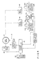
- Fig. 4 is a block diagram of a control system.
- a reel motor 55 is controlled through reel motor controller 76 by a system controller 78.
- This system controller 78 receives a set signal from an operation section 80 and a select signal, which represents an operation mode according to first and second grooves 72 and 74 of cam gear 12, from a cam switch 82 and controls the loading motor 14 and the drive-force transmitting mechanism 13 in order to rotate to a desired mode position the cam gear 12 for setting the aforementioned various operation modes necessary for a VTR machine.
- the mode select signal is for selecting modes associated with the first and second cam grooves 72 and 74 of the cam gear 12.
- the supply reel stand 52a and take-up reel stand 52b respectively receive the rotational momentum of the reel motor 55 through a motor pulley 551 and a rocking gear 552.
- Disposed at proximities of these reel stands 52a and 52b are tape end detectors 84a and 84b each comprising a pulse generator, a counter, etc.
- the tape end detector 84a and 84b are designed to count the number of pulses generated from, for example, the pulse generators, and detect the amount of the tape T remaining on the reels of the individual reel stands 52a and 52b, i.e., to detect the tape end, based on the number of the pulses counted.
- Detection signals are supplied to the system controller 78 from the tape end detector 84a and 84b.
- the system controller 78 controls the main brakes 46 and 48 through the loading motor 14, drive-force transmitting mechanism 13 and cam gear 12 to thereby brake the reel stands 52a and 52b.
- the cam gear 12 is set in a slot in/out state of a VTR tape cassette and a tape is in an unloading state, which is a cam pattern 1 shown in Fig. 5, and the main brakes 46 and 48 are in operable state.
- the system controller 78 sends a drive command to the loading motor 14 upon reception of a set signal from the operation section 80, the loading motor 14 is driven to actuate the drive-force transmitting mechanism 13 to rotate the worm gear 26a in the direction of the arrow F1 in Fig. 2. Consequently, the driving force of the loading motor 14 is transmitted to the cam gear 12 through the gears 22 and 24 and worm gear 26a.
- the cam gear 12 starts rotating in the direction of the arrow H1 in Fig. 3 and the cam pin 30 of the cam lever 28 moves along the first groove 72 so as to set the mode to the short fast-forward state of the cam pattern 2 and further to the loading state of the cam pattern 3 in accordance with the setting of the operation section 80.
- the tape T wound around the reels mounted on the supply reel stand 52a and take-up reel stand 52b is fed-out by the tape guides 53a and 53b. After passing by a predetermined path, the fed-out tape T is wound around the cylinder 54 having the magnetic head, and the tape cassette is now in loaded state.
- the cam pin 30 moves along the first groove 72 to set the mode to a review or reverse mode by the cam pattern 4 or a playback, record, cue or slow mode by the cam pattern 5.
- Changing the cam patterns of the cam gear 12 actuates the cam switch 82 to send a mode select signal associated with each operation mode to the system controller 78.
- the system controller 78 detects that the drive-force transmitting mechanism 13 is switched to a mode set by the operation section 80 and sets an electric circuit in the mode.
- system controller 78 controls the reel motor controller 76 to drive the reel motor 55 for rotating the reel stand 52a or 52b at a speed according to the selected mode.
- the first small-diameter portion 721 of the first groove 72 of the cam gear 12 has the same diameter. In each of the above modes, therefore, the cam pin 30 stays abutting on the projection 62b of the lock lever 62. As a result, the cam lever 28, brake connector 36, brake switching lever 40 and brake slider 42 are pulled in the directions of the arrows A2, B2, C2, and D2, respectively. In other words, in the modes of the cam patterns 2 to 5, the rollers 46a and 48a of the main brakes 46 and 48 are in abutment with the slanted sections 42b and 42c of the brake slider 42, respectively. Accordingly, the brake shoes 46b and 48b of the main brakes 46 and 48 are separated from the outer surfaces of the supply reel stand 52a and take-up reel stand 52b, thus inhibiting the main brake mechanism from being driven.
- the system controller 78 When the system controller 78 receives the set signal from the operation section 80 which is associated with the stop mode indicated by the cam pattern 6, it causes the cam pin 30 of the cam lever 28 to come to the position for the stop mode. Then, the mode select signal is output to the system controller 78 from the cam switch 82. Upon reception of this signal, the controller 78 stops the loading motor 14 to stop rotating the cam gear 12. At this time, the system controller 78 is permitting the reel motor controller 76 to stop the reel motor. At the same time, the stop mode causes the main brake mechanism to be driven to actuate the main brakes 46 and 48.
- the cam pin 30 of the cam lever 28 is positioned at a first large-diameter portion 722 of the first groove 72 as shown in Fig. 3. Therefore, the cam lever 28 rotates in the direction of the arrow A1 around the support shaft 32.
- the brake connector 36 slides in the direction of the arrow B1
- the brake switching lever 40 rotates in the direction of the arrow C1
- brake slider 42 slides in the direction of the arrow D1.
- the rollers 46a and 48a of the main brakes 46 and 48 which are in abutment with the slanted sections 42b and 42c, come to the linear portions of the end portion and body 42a of the brake slider 42.
- the second spring 50 causes the main brake 46 to rotate in the counterclockwise direction in Fig. 1 while causing the main brake 48 to rotate clockwise. This presses the brake shoes 46b and 48b against the reel stands 52a and 52b to thereby apply braking thereto.
- the system controller 78 drives the loading motor 14 again.
- This causes the cam gear 12 to rotate via the drive-force transmitting mechanism 13 such as the worm gear 26a, thus releasing the main brakes 46 and 48. That is, the cam pin 30 of the cam lever 28 comes to a second small-diameter portion 723 of the first groove 72 of the cam gear 12 as shown in Fig. 3.
- This causes the cam lever 28 to rotate in the direction of the arrow A2 again.
- the brake connector 36 is moved in the direction of the arrow B2 and the brake switching lever 40 rotates in the direction of the arrow C2.
- the brake slider 42 slides in the direction of the arrow D2, thus causing the rollers 46a and 48a of the main brakes 46 and 48 to move over the slanted section 42b and 42c of the brake slider 42 again. Then, the brake shoes 46b and 48b are respectively separated from the outer surfaces of the reel stands 52a and 52b, thus releasing the braking.
- the system controller 78 controls the reel motor controller 76 to drive the reel motor 55 to rotate the desired reel stand 52a or 52b.
- the cam pin 30 comes to the large-diameter portion 724 of the first cam groove 72. Since the cam pin 30 is locked within the recess 62a of the lock lever 62, however, the cam lever 28, brake connector 36, brake switching lever 40 and brake slider 42 are in a state where no braking is effected, as in the aforementioned case where the cam pin 30 is located at the second small-diameter portion 723. Although the cam pin 70 is located at the diameter portion 741 of the second cam groove 74 at this time, the lock of the cam lever 28 will not be released by the help of the fourth spring 68 provided between the lock release lever 64 and support plate 58.
- the brake slider 42 coupled to the cam lever 28 through the brake connector 36 and brake switching lever 40 is immediately moved in the direction of the arrow D1 by the urging force of the first spring 44.
- the rollers 46a and 48a of the main brakes 46 and 48 immediately slide the slanted sections 42b and 42c to rotate the main brakes 46 ad 48 in a predetermined direction. Accordingly, the brake shoes 46b and 48b of the main brakes 46 and 48 abut on the outer surfaces of the reel stands 52a and 52b to apply braking thereto.
- the reel motor controller 76 stops the reel motor 55 under the control of the system controller 78, thereby stopping the reel stands 52a and 52b.
- the pattern for the high-speed tape running mode such as FF/REW is provided at the end portion of the cam grooves for the loading/unloading mode.
- the cam gear 12 in high-speed mode (cam pattern 7) is rotated in the direction of the arrow H2 or in the direction of the unloading mode, therefore, the lock of the cam lever 28 is instantaneously released and braking can be immediately effected.
- the shaded portion for ON/OFF of the main brake is where braking can be effected immediately upon lock release.
- the loading motor 14 starts rotating in the direction opposite to the loading direction and the brake slider 42 is immediately moved by releasing the lock of the cam lever 28 caused by the lock lever 62 to thereby permit the main brakes 46 and 48 to brake the reel stands 52a and 52b. It is, therefore, possible to effect braking immediately upon detection of the signal. This can minimize the need to decelerate the running speed of the magnetic tape near the tape end and thus ensure high-speed tape running.
- braking is effected by the operation of the lock release lever when the tape end is detected by the tape end detectors 84a and 84b, braking may be effected immediately upon occurrence of such an event that the tape T is twisted around a running system in high-speed mode.
Landscapes
- Braking Arrangements (AREA)
- Unwinding Webs (AREA)
Applications Claiming Priority (2)
| Application Number | Priority Date | Filing Date | Title |
|---|---|---|---|
| JP63074412A JP2610293B2 (ja) | 1988-03-30 | 1988-03-30 | リール台ブレーキ機構 |
| JP74412/88 | 1988-03-30 |
Publications (3)
| Publication Number | Publication Date |
|---|---|
| EP0335377A2 true EP0335377A2 (fr) | 1989-10-04 |
| EP0335377A3 EP0335377A3 (en) | 1990-12-27 |
| EP0335377B1 EP0335377B1 (fr) | 1996-02-07 |
Family
ID=13546454
Family Applications (1)
| Application Number | Title | Priority Date | Filing Date |
|---|---|---|---|
| EP89105550A Expired - Lifetime EP0335377B1 (fr) | 1988-03-30 | 1989-03-29 | Appareil de freinage de bande magnétique à grande vitesse |
Country Status (5)
| Country | Link |
|---|---|
| US (1) | US4977467A (fr) |
| EP (1) | EP0335377B1 (fr) |
| JP (1) | JP2610293B2 (fr) |
| KR (1) | KR920010457B1 (fr) |
| DE (1) | DE68925592T2 (fr) |
Cited By (5)
| Publication number | Priority date | Publication date | Assignee | Title |
|---|---|---|---|---|
| DE4042138A1 (de) * | 1989-12-31 | 1991-07-11 | Samsung Electronics Co Ltd | Spulentellerbremsvorrichtung fuer ein videobandgeraet |
| EP0497271A1 (fr) * | 1991-01-31 | 1992-08-05 | Samsung Electronics Co. Ltd. | Dispositif de mouvement de freins d'un enregistreur à bande |
| WO1993001594A1 (fr) * | 1991-07-01 | 1993-01-21 | Funai Electric Co., Ltd. | Dispositif de selection du mode de commande d'une bobine de bande |
| EP0560994A1 (fr) * | 1991-10-04 | 1993-09-22 | Sony Corporation | Dispositif d'entrainement de bande |
| US5640262A (en) * | 1991-10-23 | 1997-06-17 | Sony Corporation | Control system and connecting device |
Families Citing this family (6)
| Publication number | Priority date | Publication date | Assignee | Title |
|---|---|---|---|---|
| KR920008478B1 (ko) * | 1990-01-06 | 1992-09-30 | 삼성전자 주식회사 | 디에이티용 리일 브레이크의 제어장치 |
| JPH03296949A (ja) * | 1990-04-16 | 1991-12-27 | Clarion Co Ltd | ブレーキ機構 |
| JP2940171B2 (ja) * | 1991-01-30 | 1999-08-25 | ソニー株式会社 | テープ記録再生装置のサーボ制御装置 |
| US5406425A (en) * | 1991-08-06 | 1995-04-11 | R-Byte, Inc. | ISO/IEC compatible digital audio tape digital data storage system with increased data transfer rate |
| KR940010201B1 (ko) * | 1992-01-07 | 1994-10-22 | 삼성전자 주식회사 | 전송장치의 병렬처리 방식에 의한 ds3/ds4 신호의 다중화 회로 |
| KR100525693B1 (ko) | 1996-08-27 | 2005-11-03 | 산에이겐 에후.에후. 아이. 가부시키가이샤 | 네이티브젤란검의 신규 용도 |
Citations (5)
| Publication number | Priority date | Publication date | Assignee | Title |
|---|---|---|---|---|
| US4452409A (en) * | 1981-06-15 | 1984-06-05 | Clarion Co., Ltd. | Braking system for a tape player |
| EP0168987A1 (fr) * | 1984-06-20 | 1986-01-22 | Sony Corporation | Appareil d'enregistrement et/ou de reproduction magnétique |
| EP0236962A2 (fr) * | 1986-03-12 | 1987-09-16 | Hitachi, Ltd. | Système de freinage pour un appareil d'enregistrement et de reproduction magnétique |
| US4779153A (en) * | 1986-06-27 | 1988-10-18 | Hitachi, Ltd. | Brake control mechanism for magnetic recording and reproducing apparatus |
| US4807061A (en) * | 1986-12-31 | 1989-02-21 | Goldstar Co., Ltd. | Rapid reel braking device for a video cassette tape recorder |
Family Cites Families (2)
| Publication number | Priority date | Publication date | Assignee | Title |
|---|---|---|---|---|
| US4500049A (en) * | 1981-09-02 | 1985-02-19 | Pioneer Electronic Corporation | Device for automatically stopping a tape recorder |
| US4899951A (en) * | 1987-10-30 | 1990-02-13 | Clarion Co., Ltd. | Braking mechanism for use in a magnetic recording apparatus |
-
1988
- 1988-03-30 JP JP63074412A patent/JP2610293B2/ja not_active Expired - Lifetime
-
1989
- 1989-03-29 US US07/330,283 patent/US4977467A/en not_active Expired - Lifetime
- 1989-03-29 DE DE68925592T patent/DE68925592T2/de not_active Expired - Lifetime
- 1989-03-29 EP EP89105550A patent/EP0335377B1/fr not_active Expired - Lifetime
- 1989-03-30 KR KR1019890004161A patent/KR920010457B1/ko not_active IP Right Cessation
Patent Citations (5)
| Publication number | Priority date | Publication date | Assignee | Title |
|---|---|---|---|---|
| US4452409A (en) * | 1981-06-15 | 1984-06-05 | Clarion Co., Ltd. | Braking system for a tape player |
| EP0168987A1 (fr) * | 1984-06-20 | 1986-01-22 | Sony Corporation | Appareil d'enregistrement et/ou de reproduction magnétique |
| EP0236962A2 (fr) * | 1986-03-12 | 1987-09-16 | Hitachi, Ltd. | Système de freinage pour un appareil d'enregistrement et de reproduction magnétique |
| US4779153A (en) * | 1986-06-27 | 1988-10-18 | Hitachi, Ltd. | Brake control mechanism for magnetic recording and reproducing apparatus |
| US4807061A (en) * | 1986-12-31 | 1989-02-21 | Goldstar Co., Ltd. | Rapid reel braking device for a video cassette tape recorder |
Cited By (10)
| Publication number | Priority date | Publication date | Assignee | Title |
|---|---|---|---|---|
| DE4042138A1 (de) * | 1989-12-31 | 1991-07-11 | Samsung Electronics Co Ltd | Spulentellerbremsvorrichtung fuer ein videobandgeraet |
| GB2239980A (en) * | 1989-12-31 | 1991-07-17 | Samsung Electronics Co Ltd | Reel disc braking device for a video tape recorder |
| EP0497271A1 (fr) * | 1991-01-31 | 1992-08-05 | Samsung Electronics Co. Ltd. | Dispositif de mouvement de freins d'un enregistreur à bande |
| WO1993001594A1 (fr) * | 1991-07-01 | 1993-01-21 | Funai Electric Co., Ltd. | Dispositif de selection du mode de commande d'une bobine de bande |
| GB2263187A (en) * | 1991-07-01 | 1993-07-14 | Funai Electric Co | Device for selecting tape-reel control mode |
| US5398880A (en) * | 1991-07-01 | 1995-03-21 | Funai Electric Co., Ltd. | Device for selecting tape-reel control mode |
| GB2263187B (en) * | 1991-07-01 | 1995-10-04 | Funai Electric Co | Device for selecting tape-reel control mode |
| EP0560994A1 (fr) * | 1991-10-04 | 1993-09-22 | Sony Corporation | Dispositif d'entrainement de bande |
| EP0560994A4 (en) * | 1991-10-04 | 1996-02-28 | Sony Corp | Tape driving device |
| US5640262A (en) * | 1991-10-23 | 1997-06-17 | Sony Corporation | Control system and connecting device |
Also Published As
| Publication number | Publication date |
|---|---|
| DE68925592D1 (de) | 1996-03-21 |
| EP0335377B1 (fr) | 1996-02-07 |
| DE68925592T2 (de) | 1996-06-20 |
| KR900015106A (ko) | 1990-10-25 |
| EP0335377A3 (en) | 1990-12-27 |
| JP2610293B2 (ja) | 1997-05-14 |
| KR920010457B1 (ko) | 1992-11-28 |
| JPH01248347A (ja) | 1989-10-03 |
| US4977467A (en) | 1990-12-11 |
Similar Documents
| Publication | Publication Date | Title |
|---|---|---|
| US4214283A (en) | Drive mechanism for cassette tape recorders | |
| US4977467A (en) | Magnetic tape high-speed braking apparatus | |
| EP0404426B1 (fr) | Mécanisme de changement de mode de fonctionnement pour appareil d'enregistrement et/ou de reproduction à bande | |
| EP0306230B1 (fr) | Appareil d'enregistrement et/ou de reproduction pour une cassette à bande magnétique | |
| JP3167322B2 (ja) | テープの張力を調整する方法 | |
| US4075670A (en) | Tape auto-loading recording and reproducing apparatus | |
| EP0297806B1 (fr) | Mécanisme de bobinage/rebobinage rapides pour enregistrement sur bande et/ou appareil de reproduction | |
| EP0580031A2 (fr) | Appareil de sélection d'un mode de fonctionnement d'un système d'enregistrement et de reproduction pour un appareil d'enregistrement à cassette à bande | |
| JPH07169148A (ja) | ビデオカセットレコーダのリールテーブル駆動装置 | |
| KR920010839B1 (ko) | 릴 및 테이프 제동장치 | |
| KR100188074B1 (ko) | 릴 및 테이프 구동부를 구비한 레코더 | |
| CA1114945A (fr) | Appareil d'enregistrement et/ou de lecture sur bande magnetique | |
| US5418662A (en) | Cassette loading system for recording and reproducing apparatus that switches from both reels powered to only one reel powered during withdrawal of tape into cassette | |
| JPS58147835A (ja) | 磁気テ−プ装置 | |
| EP0343252B1 (fr) | Dispositif d'entrainement de bande magnetique a grande vitesse | |
| JP2954739B2 (ja) | 磁気記録再生装置のカム操作機構 | |
| JPS6338431Y2 (fr) | ||
| JP2001093207A (ja) | 磁気記録再生装置 | |
| JPS5880161A (ja) | 磁気記録再生装置 | |
| JPH081713B2 (ja) | 磁気記録再生装置 | |
| JP2001101735A (ja) | 磁気記録再生装置 | |
| JP2001093208A (ja) | 磁気記録再生装置 | |
| JPH0668551A (ja) | リール台のブレーキ装置 | |
| JPS6214355A (ja) | テ−プ送り装置 | |
| JPS62270048A (ja) | 磁気記録再生装置 |
Legal Events
| Date | Code | Title | Description |
|---|---|---|---|
| PUAI | Public reference made under article 153(3) epc to a published international application that has entered the european phase |
Free format text: ORIGINAL CODE: 0009012 |
|
| 17P | Request for examination filed |
Effective date: 19890426 |
|
| AK | Designated contracting states |
Kind code of ref document: A2 Designated state(s): DE FR GB |
|
| PUAL | Search report despatched |
Free format text: ORIGINAL CODE: 0009013 |
|
| AK | Designated contracting states |
Kind code of ref document: A3 Designated state(s): DE FR GB |
|
| 17Q | First examination report despatched |
Effective date: 19920925 |
|
| GRAA | (expected) grant |
Free format text: ORIGINAL CODE: 0009210 |
|
| AK | Designated contracting states |
Kind code of ref document: B1 Designated state(s): DE FR GB |
|
| REF | Corresponds to: |
Ref document number: 68925592 Country of ref document: DE Date of ref document: 19960321 |
|
| ET | Fr: translation filed | ||
| PLBE | No opposition filed within time limit |
Free format text: ORIGINAL CODE: 0009261 |
|
| STAA | Information on the status of an ep patent application or granted ep patent |
Free format text: STATUS: NO OPPOSITION FILED WITHIN TIME LIMIT |
|
| 26N | No opposition filed | ||
| REG | Reference to a national code |
Ref country code: GB Ref legal event code: 746 Effective date: 19981008 |
|
| REG | Reference to a national code |
Ref country code: FR Ref legal event code: D6 |
|
| REG | Reference to a national code |
Ref country code: GB Ref legal event code: IF02 |
|
| PGFP | Annual fee paid to national office [announced via postgrant information from national office to epo] |
Ref country code: DE Payment date: 20080407 Year of fee payment: 20 Ref country code: FR Payment date: 20080311 Year of fee payment: 20 |
|
| PGFP | Annual fee paid to national office [announced via postgrant information from national office to epo] |
Ref country code: GB Payment date: 20080402 Year of fee payment: 20 |
|
| REG | Reference to a national code |
Ref country code: GB Ref legal event code: PE20 Expiry date: 20090328 |
|
| PG25 | Lapsed in a contracting state [announced via postgrant information from national office to epo] |
Ref country code: GB Free format text: LAPSE BECAUSE OF EXPIRATION OF PROTECTION Effective date: 20090328 |