EP0335154A1 - Schlauchleitung mit einem weichelastischen Mantel - Google Patents
Schlauchleitung mit einem weichelastischen Mantel Download PDFInfo
- Publication number
- EP0335154A1 EP0335154A1 EP89104318A EP89104318A EP0335154A1 EP 0335154 A1 EP0335154 A1 EP 0335154A1 EP 89104318 A EP89104318 A EP 89104318A EP 89104318 A EP89104318 A EP 89104318A EP 0335154 A1 EP0335154 A1 EP 0335154A1
- Authority
- EP
- European Patent Office
- Prior art keywords
- hose line
- hose
- rib strips
- line according
- rib
- Prior art date
- Legal status (The legal status is an assumption and is not a legal conclusion. Google has not performed a legal analysis and makes no representation as to the accuracy of the status listed.)
- Granted
Links
Images
Classifications
-
- F—MECHANICAL ENGINEERING; LIGHTING; HEATING; WEAPONS; BLASTING
- F16—ENGINEERING ELEMENTS AND UNITS; GENERAL MEASURES FOR PRODUCING AND MAINTAINING EFFECTIVE FUNCTIONING OF MACHINES OR INSTALLATIONS; THERMAL INSULATION IN GENERAL
- F16L—PIPES; JOINTS OR FITTINGS FOR PIPES; SUPPORTS FOR PIPES, CABLES OR PROTECTIVE TUBING; MEANS FOR THERMAL INSULATION IN GENERAL
- F16L11/00—Hoses, i.e. flexible pipes
- F16L11/04—Hoses, i.e. flexible pipes made of rubber or flexible plastics
- F16L11/12—Hoses, i.e. flexible pipes made of rubber or flexible plastics with arrangements for particular purposes, e.g. specially profiled, with protecting layer, heated, electrically conducting
- F16L11/121—Hoses, i.e. flexible pipes made of rubber or flexible plastics with arrangements for particular purposes, e.g. specially profiled, with protecting layer, heated, electrically conducting specially profiled cross sections
-
- F—MECHANICAL ENGINEERING; LIGHTING; HEATING; WEAPONS; BLASTING
- F16—ENGINEERING ELEMENTS AND UNITS; GENERAL MEASURES FOR PRODUCING AND MAINTAINING EFFECTIVE FUNCTIONING OF MACHINES OR INSTALLATIONS; THERMAL INSULATION IN GENERAL
- F16L—PIPES; JOINTS OR FITTINGS FOR PIPES; SUPPORTS FOR PIPES, CABLES OR PROTECTIVE TUBING; MEANS FOR THERMAL INSULATION IN GENERAL
- F16L57/00—Protection of pipes or objects of similar shape against external or internal damage or wear
-
- D—TEXTILES; PAPER
- D06—TREATMENT OF TEXTILES OR THE LIKE; LAUNDERING; FLEXIBLE MATERIALS NOT OTHERWISE PROVIDED FOR
- D06F—LAUNDERING, DRYING, IRONING, PRESSING OR FOLDING TEXTILE ARTICLES
- D06F33/00—Control of operations performed in washing machines or washer-dryers
- D06F33/30—Control of washing machines characterised by the purpose or target of the control
- D06F33/47—Responding to irregular working conditions, e.g. malfunctioning of pumps
Definitions
- the invention is based on a hose line with a soft elastic jacket for a washing machine set up for spinning.
- Hose lines that are drawn between fixed hose connections that swivel strongly together with the tub assembly when spinning also swing when spinning.
- rounds of soft elastic material, for example of foam have been drawn over such hose lines, which prevent the hose line from constantly beating against any parts inside the washing machine when it swings.
- the invention has for its object to provide means for such a hose line, which make it unnecessary to install such blanks, without having to forego the protection of the hose lines and noise reduction.
- this object is achieved in that the outer circumferential surface is provided with rib strips distributed along the circumference and guided along the longitudinal extent of the hose line.
- Rib strips of this type increase the distance between the hose line and other machine parts. Since the rib strips are more flexible than the wall of the hose line itself, not as much material and above all not from the outer jacket surface is removed when hitting and rubbing against machine parts as with the known smooth-walled hose lines. In addition, there is considerably less noise when spinning than with smooth-walled hose lines.
- the flexibility for the rib strips can be increased in that the rib strips have a wide base and an acute-angled ridge.
- the noise insulation is also particularly good.
- the rib strips form a star-shaped cross section for the hose line.
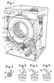
- a pressure transmitter housing 4 is connected to the drain hose 1 from the tub 2 of the washing machine shown in FIG.
- discs 7 made of soft elastic foam are drawn over the hose line and fixed at such heights at which the hose line 5 can come into contact with parts of the washing machine.
- Such parts can be, for example, the support frame 8 for the tub 2 or the outer surface of the tub itself. When spinning these parts vibrate strongly and would hit the hose line 5 if it were not protected.
- the hose line 5 is protected by rib strips 5, which run along its jacket in the longitudinal extent of the hose line. 2, eight such rib strips are distributed in a star shape on the circumference. They can have a triangular cross-section with a wide base 10 and an acute-angled ridge 11 and stand radially on the outer surface of the hose line.
- the triangular rib strips 12 can also be at an angle to the radius R of the tube cross-section on the outer surface.
- the shorter flank 14 of the rib strip 12 can have a concave shape.
- the rib strip 15 shown in FIG. 4 has an angled triangular cross section, so that the cross section as a whole is somewhat more flexible.
- the ribbed strip 16 which is curved in a crescent shape according to FIG. 5, should offer the best prerequisites in terms of flexibility.
- Rubber is preferably used as the material for the hose line 5, so that maximum protection of the material and noise reduction can be achieved when the lips 11, 13, 17 or 18 are formed flat.
- the rib strips which are distributed more or less in number on the circumference, can run parallel to the central axis of the hose line or can be wound around the hose line.
- the helix angle should not deviate significantly from 90 ° to the cross-sectional plane of the hose line.
Abstract
Description
- Die Erfindung geht aus von einer Schlauchleitung mit einem weichelastischen Mantel für eine zum Schleudern eingerichtete Waschmaschine.
- Im Innenraum von bekannten Waschmaschinen sind unterschiedliche Schlauchleitungen verlegt. Schlauchleitungen, die zwischen ortsfesten und zusammen mit dem Laugenbehälter-Aggregat beim Schleudern stark schwingenden Schlauchanschlüssen gezogen sind, schwingen beim Schleudern ebenfalls. Zum Schutze dieser Schlauchleitungen vor schnellem Verschleiß und zur Geräuschdämpfung hat man über solche Schlauchleitungen Ronden aus weichelastischem Material, z.B. aus Schaumstoff, gezogen, die beim Schwingen ein ständiges Schlagen der Schlauchleitung an irgendwelchen Teilen innerhalb der Waschmaschine verhindern.
- Der Erfindung liegt die Aufgabe zugrunde, Mittel für eine solche Schlauchleitung anzugeben, die das Aufziehen derartiger Ronden entbehrlich machen, ohne auf den Schutz der Schlauchleitungen und auf die Geräuschdämpfung verzichten zu müssen.
- Erfindungsgemäß wird diese Aufgabe dadurch gelöst, daß die Außenmantelfläche mit entlang der Längserstreckung der Schlauchleitung geführten, am Umfang verteilten Rippenleisten versehen ist.
- Derartige Rippenleisten erhöhen den Abstand zwischen der Schlauchleitung und anderen Maschinenteilen. Da die Rippenleisten nachgiebiger sind als die Wandung der Schlauchleitung selbst, wird beim Schlagen und Scheuern an Maschinenteilen nicht soviel Material und vor allem nicht von der Außenmantelfläche abgetragen wie bei den bekannten glattwandigen Schlauchleitungen. Außerdem entstehen damit erheblich weniger Geräusche beim Schleudern als mit glattwandigen Schlauchleitungen.
- Die Nachgiebigkeit für die Rippenleisten läßt sich dadurch erhöhen, daß die Rippenleisten einen breiten Fuß und einen spitzwinkligen First aufweisen.
- Wenn die Firstkante gemäß einer vorteilhaften Ausbildung der Erfindung eine besonders weichelastische Rippe bildet, ist auch die Geräuschdämmung besonders gut.
- Um die Schlauchleitung von allen Seiten gut zu schützen, bilden die Rippenleisten erfindungsgemäß einen sternförmigen Querschnitt für die Schlauchleitung.
- Eine noch bessere Nachgiebigkeit der Rippen läßt sich dadurch erzielen, daß die Querschnittsflächen der Rippenleisten gebogen oder geknickt sind oder daß die Rippenleisten mit steilem Winkel zur Längserst reckung der Schlauchleitung um diese gewendelt sind.
- Anhand einiger in der Zeichnung dargestellter Ausführungsbeispiele ist die Erfindung nachstehend erläutert.
- Es zeigen:
- Fig. 1 schematisch eine durchsichtige Waschmaschine mit einer von Ronden bezogenen Schlauchleitung,
- Fig. 2 den Querschnitt einer erfindungsgemäß ausgestalteten Schlauchleitung und
- Fig. 3 bis 5 verschiedene Querschnitt von anderen Ausführungsbeispielen von Rippenleisten.
- Am Abflußschlauch 1 aus dem über Federbeine 3 schwingbeweglich gelagerten Laugenbehälter 2 der in Fig. 1 dargestellten Waschmaschine ist ein Druckgebergehäuse 4 angeschlossen, das über eine Schlauchleitung 5 mit einem oben in der Waschmaschine ortsfest angeordneten Membranschalter 6 verbunden ist. Über die Schlauchleitung sind bekanntermaßen Ronden 7 aus weichelastischem Schaumstoff gezogen und in solchen Höhen fixiert, in denen die Schlauchleitung 5 mit Teilen der Waschmaschine in Berührung kommen kann. Solche Teile können beispielsweise das Traggestell 8 für den Laugenbehälter 2 oder die Außenfläche des Laugenbehälters selbst sein. Beim Schleudern schwingen diese Teile stark und würden mit der Schlauchleitung 5 zusammenschlagen, wäre sie nicht geschützt.
- Erfindungsgemäß ist die Schlauchleitung 5 durch Rippenleisten 5 geschützt, die in der Längserstreckung der Schlauchleitung an ihrem Mantel entlang verlaufen. Gemäß Fig. 2 sind acht solcher Rippenleisten sternförmig am Umfang verteilt. Sie können dreieckigen Querschnitt mit breitem Fuß 10 und spitzwinkligen First 11 aufweisen und radial auf der Mantelfläche der Schlauchleitung stehen.
- Gemäß Fig. 3 können die dreieckig profilierten Rippenleisten 12 aber auch in einem Winkel zum Radius R des Schlauchquerschnittes auf der Mantelfläche stehen. Zur Erhöhung der Nachgiebigkeit der Lippe 13 kann die kürzere Flanke 14 der Rippenleiste 12 konkav geformt sein.
- Die in Fig. 4 dargestellte Rippenleiste 15 hat einen abgewinkelten Dreiecks-Querschnitt, damit der Querschnitt insgesamt etwas biegsamer wird.
- Die im Querschnitt sichelförmig gebogene Rippenleiste 16 gemäß Fig. 5 dürfte hinsichtlich der Nachgiebigkeit die besten Voraussetzungen bieten.
- Als Werkstoff für die Schlauchleitung 5 kommt vorzugsweise Gummi in Betracht, so daß bei flacher Ausformung der Lippen 11, 13, 17 oder 18 ein Maximum an Werkstoffschonung und Geräuschdämpfung zu erzielen ist.
- Die mehr oder weniger zahlreich am Umfang verteilten Rippenleisten können parallel zur Mittelachse der Schlauchleitung verlaufen oder um die Schlauchleitung herum gewendelt sein. Der Wendelwinkel sollte aber nicht wesentlich von 90° zur Querschnittsebene der Schlauchleitung abweichen.
Claims (6)
Applications Claiming Priority (2)
| Application Number | Priority Date | Filing Date | Title |
|---|---|---|---|
| DE3810861 | 1988-03-30 | ||
| DE3810861A DE3810861A1 (de) | 1988-03-30 | 1988-03-30 | Schlauchleitung mit einem weichelastischen mantel |
Publications (2)
| Publication Number | Publication Date |
|---|---|
| EP0335154A1 true EP0335154A1 (de) | 1989-10-04 |
| EP0335154B1 EP0335154B1 (de) | 1993-02-24 |
Family
ID=6351106
Family Applications (1)
| Application Number | Title | Priority Date | Filing Date |
|---|---|---|---|
| EP19890104318 Expired - Lifetime EP0335154B1 (de) | 1988-03-30 | 1989-03-10 | Schlauchleitung mit einem weichelastischen Mantel |
Country Status (4)
| Country | Link |
|---|---|
| EP (1) | EP0335154B1 (de) |
| DE (2) | DE3810861A1 (de) |
| ES (1) | ES2037895T3 (de) |
| HK (1) | HK144295A (de) |
Families Citing this family (2)
| Publication number | Priority date | Publication date | Assignee | Title |
|---|---|---|---|---|
| DE20102973U1 (de) * | 2001-02-07 | 2001-07-05 | Muendener Gummiwerk Gmbh | Elastomerschlauch für Kraftfahrzeuge, z.B. Turboladerschlauch |
| ES2559689B1 (es) * | 2014-08-14 | 2016-12-01 | BSH Hausgeräte GmbH | Aparato doméstico con un tubo portador de un agente y un manguito retráctil circundante, método para producir un aparato doméstico, y uso de un tubo |
Citations (3)
| Publication number | Priority date | Publication date | Assignee | Title |
|---|---|---|---|---|
| LU82956A1 (de) * | 1980-09-12 | 1981-03-26 | Feist Artus | Aus einem flexiblen oder steifen kunststoff bestehendes rohr zum transport eines waermetraegers |
| US4410012A (en) * | 1980-10-20 | 1983-10-18 | The United States Of America As Represented By The Secretary Of The Navy | Radially compliant acoustic line array hose |
| EP0092026A2 (de) * | 1982-04-19 | 1983-10-26 | Hoesch Aktiengesellschaft | Metallrohr mit Schutzüberzug und integriertem Steinschutz |
Family Cites Families (1)
| Publication number | Priority date | Publication date | Assignee | Title |
|---|---|---|---|---|
| DE1737232U (de) * | 1956-10-31 | 1957-01-03 | Hutchinson Gummiwarenfabrik | Gummischlauch. |
-
1988
- 1988-03-30 DE DE3810861A patent/DE3810861A1/de not_active Withdrawn
-
1989
- 1989-03-10 EP EP19890104318 patent/EP0335154B1/de not_active Expired - Lifetime
- 1989-03-10 ES ES198989104318T patent/ES2037895T3/es not_active Expired - Lifetime
- 1989-03-10 DE DE8989104318T patent/DE58903582D1/de not_active Expired - Fee Related
-
1995
- 1995-09-07 HK HK144295A patent/HK144295A/xx not_active IP Right Cessation
Patent Citations (3)
| Publication number | Priority date | Publication date | Assignee | Title |
|---|---|---|---|---|
| LU82956A1 (de) * | 1980-09-12 | 1981-03-26 | Feist Artus | Aus einem flexiblen oder steifen kunststoff bestehendes rohr zum transport eines waermetraegers |
| US4410012A (en) * | 1980-10-20 | 1983-10-18 | The United States Of America As Represented By The Secretary Of The Navy | Radially compliant acoustic line array hose |
| EP0092026A2 (de) * | 1982-04-19 | 1983-10-26 | Hoesch Aktiengesellschaft | Metallrohr mit Schutzüberzug und integriertem Steinschutz |
Also Published As
| Publication number | Publication date |
|---|---|
| EP0335154B1 (de) | 1993-02-24 |
| DE3810861A1 (de) | 1989-10-12 |
| HK144295A (en) | 1995-09-15 |
| ES2037895T3 (es) | 1993-07-01 |
| DE58903582D1 (de) | 1993-04-01 |
Similar Documents
| Publication | Publication Date | Title |
|---|---|---|
| EP0612944B1 (de) | Einteiliges Halteelement | |
| DE3428650A1 (de) | Haartrockner mit axialgeblaese | |
| EP1422459A1 (de) | Abdichtsystem | |
| DE60128630T2 (de) | Durchführungstülle | |
| DE3337344A1 (de) | Tragbare schlauchwickelvorrichtung, insbesondere fuer wagen, caravans, omnibusse, schiffe, balkone und kleine gaerten | |
| DE4326793C1 (de) | Rotativ antreibbares Bürstenaggregat | |
| CA2035954A1 (en) | Debris impeller | |
| EP0335154A1 (de) | Schlauchleitung mit einem weichelastischen Mantel | |
| DE6801232U (de) | Halbaxiales ventilatorlaufrad | |
| DE4141802C2 (de) | Kehrmaschine | |
| DE3330199A1 (de) | Foedergeblaese fuer textiles fasergut | |
| EP0458083B1 (de) | In einer Dachöffnung eines Kraftfahrzeuges aufgenommener Deckel | |
| EP1734256B1 (de) | Anordnung zur Abdichtung eines Lüfters | |
| DE1503541A1 (de) | Filter-Geblaese | |
| DE69931581T2 (de) | Kabeldurchführungsanordnung | |
| DE3707920A1 (de) | Gehaeuse fuer ein radialgeblaese | |
| AT977U1 (de) | Wärmedämmendes element für körper, insbesondere für warmwasserspeicher | |
| EP0296447B1 (de) | Lüfteranordnung für eine aussenbelüftete elektrische Maschine | |
| DE2241654A1 (de) | Lufteinlass fuer geblaese | |
| DE102020103712B3 (de) | Druckgasentlaubungsvorrichtung | |
| CH618645A5 (de) | ||
| DE4042126C1 (en) | Plastics impeller for radial-flow fan - has annular cover disc with cylindrical inlet branch and flat fructo=conical outlet section | |
| DE3708130A1 (de) | Luefterwalze fuer geraete des persoenlichen bedarfs | |
| DE2721530B1 (de) | Bürstvorsatzgerät für einen Staubsauger | |
| DE1907577C (de) | Signalgeber |
Legal Events
| Date | Code | Title | Description |
|---|---|---|---|
| PUAI | Public reference made under article 153(3) epc to a published international application that has entered the european phase |
Free format text: ORIGINAL CODE: 0009012 |
|
| AK | Designated contracting states |
Kind code of ref document: A1 Designated state(s): DE ES FR GB IT |
|
| 17P | Request for examination filed |
Effective date: 19900206 |
|
| 17Q | First examination report despatched |
Effective date: 19910208 |
|
| GRAA | (expected) grant |
Free format text: ORIGINAL CODE: 0009210 |
|
| AK | Designated contracting states |
Kind code of ref document: B1 Designated state(s): DE ES FR GB IT |
|
| REF | Corresponds to: |
Ref document number: 58903582 Country of ref document: DE Date of ref document: 19930401 |
|
| ET | Fr: translation filed | ||
| ITF | It: translation for a ep patent filed |
Owner name: STUDIO JAUMANN |
|
| GBT | Gb: translation of ep patent filed (gb section 77(6)(a)/1977) |
Effective date: 19930527 |
|
| REG | Reference to a national code |
Ref country code: ES Ref legal event code: FG2A Ref document number: 2037895 Country of ref document: ES Kind code of ref document: T3 |
|
| RAP4 | Party data changed (patent owner data changed or rights of a patent transferred) |
Owner name: BOSCH-SIEMENS HAUSGERAETE GMBH |
|
| PLBE | No opposition filed within time limit |
Free format text: ORIGINAL CODE: 0009261 |
|
| STAA | Information on the status of an ep patent application or granted ep patent |
Free format text: STATUS: NO OPPOSITION FILED WITHIN TIME LIMIT |
|
| 26N | No opposition filed | ||
| PGFP | Annual fee paid to national office [announced via postgrant information from national office to epo] |
Ref country code: FR Payment date: 19960214 Year of fee payment: 8 |
|
| PGFP | Annual fee paid to national office [announced via postgrant information from national office to epo] |
Ref country code: GB Payment date: 19960301 Year of fee payment: 8 |
|
| PGFP | Annual fee paid to national office [announced via postgrant information from national office to epo] |
Ref country code: ES Payment date: 19960313 Year of fee payment: 8 |
|
| PGFP | Annual fee paid to national office [announced via postgrant information from national office to epo] |
Ref country code: DE Payment date: 19960429 Year of fee payment: 8 |
|
| PG25 | Lapsed in a contracting state [announced via postgrant information from national office to epo] |
Ref country code: GB Effective date: 19970310 |
|
| PG25 | Lapsed in a contracting state [announced via postgrant information from national office to epo] |
Ref country code: ES Free format text: LAPSE BECAUSE OF NON-PAYMENT OF DUE FEES Effective date: 19970311 |
|
| GBPC | Gb: european patent ceased through non-payment of renewal fee |
Effective date: 19970310 |
|
| PG25 | Lapsed in a contracting state [announced via postgrant information from national office to epo] |
Ref country code: FR Free format text: LAPSE BECAUSE OF NON-PAYMENT OF DUE FEES Effective date: 19971128 |
|
| PG25 | Lapsed in a contracting state [announced via postgrant information from national office to epo] |
Ref country code: DE Effective date: 19971202 |
|
| REG | Reference to a national code |
Ref country code: FR Ref legal event code: ST |
|
| REG | Reference to a national code |
Ref country code: ES Ref legal event code: FD2A Effective date: 19990503 |
|
| PG25 | Lapsed in a contracting state [announced via postgrant information from national office to epo] |
Ref country code: IT Free format text: LAPSE BECAUSE OF NON-PAYMENT OF DUE FEES;WARNING: LAPSES OF ITALIAN PATENTS WITH EFFECTIVE DATE BEFORE 2007 MAY HAVE OCCURRED AT ANY TIME BEFORE 2007. THE CORRECT EFFECTIVE DATE MAY BE DIFFERENT FROM THE ONE RECORDED. Effective date: 20050310 |