EP0334058B1 - Ladungsinjektionsbauelement mit rauscharmer Ausgabe - Google Patents
Ladungsinjektionsbauelement mit rauscharmer Ausgabe Download PDFInfo
- Publication number
- EP0334058B1 EP0334058B1 EP89103500A EP89103500A EP0334058B1 EP 0334058 B1 EP0334058 B1 EP 0334058B1 EP 89103500 A EP89103500 A EP 89103500A EP 89103500 A EP89103500 A EP 89103500A EP 0334058 B1 EP0334058 B1 EP 0334058B1
- Authority
- EP
- European Patent Office
- Prior art keywords
- electronic information
- defining electronic
- image
- information signals
- noise
- Prior art date
- Legal status (The legal status is an assumption and is not a legal conclusion. Google has not performed a legal analysis and makes no representation as to the accuracy of the status listed.)
- Expired - Lifetime
Links
- 238000002347 injection Methods 0.000 title claims description 24
- 239000007924 injection Substances 0.000 title claims description 24
- 230000005669 field effect Effects 0.000 claims description 12
- 239000003990 capacitor Substances 0.000 claims description 6
- 238000005070 sampling Methods 0.000 claims description 4
- 230000004044 response Effects 0.000 claims description 3
- 238000003384 imaging method Methods 0.000 description 12
- 101000637813 Homo sapiens Solute carrier family 40 member 1 Proteins 0.000 description 6
- 102100032008 Solute carrier family 40 member 1 Human genes 0.000 description 6
- 238000010586 diagram Methods 0.000 description 5
- 230000008859 change Effects 0.000 description 4
- 238000000034 method Methods 0.000 description 3
- XUIMIQQOPSSXEZ-UHFFFAOYSA-N Silicon Chemical compound [Si] XUIMIQQOPSSXEZ-UHFFFAOYSA-N 0.000 description 2
- 238000003491 array Methods 0.000 description 2
- 230000008569 process Effects 0.000 description 2
- 229910052710 silicon Inorganic materials 0.000 description 2
- 239000010703 silicon Substances 0.000 description 2
- 239000000758 substrate Substances 0.000 description 2
- 239000002800 charge carrier Substances 0.000 description 1
- 238000011161 development Methods 0.000 description 1
- 230000018109 developmental process Effects 0.000 description 1
- 230000000694 effects Effects 0.000 description 1
- 230000001747 exhibiting effect Effects 0.000 description 1
- 239000000463 material Substances 0.000 description 1
- 239000011159 matrix material Substances 0.000 description 1
- 230000008520 organization Effects 0.000 description 1
- 230000005855 radiation Effects 0.000 description 1
- 239000004065 semiconductor Substances 0.000 description 1
- 230000006641 stabilisation Effects 0.000 description 1
- 238000011105 stabilization Methods 0.000 description 1
Images
Classifications
-
- H—ELECTRICITY
- H04—ELECTRIC COMMUNICATION TECHNIQUE
- H04N—PICTORIAL COMMUNICATION, e.g. TELEVISION
- H04N25/00—Circuitry of solid-state image sensors [SSIS]; Control thereof
- H04N25/60—Noise processing, e.g. detecting, correcting, reducing or removing noise
- H04N25/65—Noise processing, e.g. detecting, correcting, reducing or removing noise applied to reset noise, e.g. KTC noise related to CMOS structures by techniques other than CDS
-
- H—ELECTRICITY
- H04—ELECTRIC COMMUNICATION TECHNIQUE
- H04N—PICTORIAL COMMUNICATION, e.g. TELEVISION
- H04N25/00—Circuitry of solid-state image sensors [SSIS]; Control thereof
- H04N25/60—Noise processing, e.g. detecting, correcting, reducing or removing noise
- H04N25/67—Noise processing, e.g. detecting, correcting, reducing or removing noise applied to fixed-pattern noise, e.g. non-uniformity of response
- H04N25/671—Noise processing, e.g. detecting, correcting, reducing or removing noise applied to fixed-pattern noise, e.g. non-uniformity of response for non-uniformity detection or correction
- H04N25/677—Noise processing, e.g. detecting, correcting, reducing or removing noise applied to fixed-pattern noise, e.g. non-uniformity of response for non-uniformity detection or correction for reducing the column or line fixed pattern noise
-
- H—ELECTRICITY
- H04—ELECTRIC COMMUNICATION TECHNIQUE
- H04N—PICTORIAL COMMUNICATION, e.g. TELEVISION
- H04N25/00—Circuitry of solid-state image sensors [SSIS]; Control thereof
- H04N25/70—SSIS architectures; Circuits associated therewith
- H04N25/76—Addressed sensors, e.g. MOS or CMOS sensors
Definitions
- This invention relates generally to a charge injection imaging device with low noise readout and, more particularly, to a charge injection imaging device which can provide image defining signals for each succeeding photosensitive element thereof from which noise defining signals are automatically offset.
- Charge injection imaging devices comprising a plurality of photosensitive elements arranged in a matrix of rows and columns are well known in the art.
- Each of the photosensitive elements comprises a row and column electrode. All the row electrodes in each row are in common connection with respect to each other, and all the column electrodes in each column are in common connection with respect to each other also.
- Incident scene light operates to photogenerate minority charge carriers in potential wells under each pair of electrodes in each photosensitive element.
- the photogenerated charges may be transferred between wells within each of the photosensitive elements by applying appropriate bias voltages to respective ones of the column and row electrodes. In one well-known mode of operation, the charges may be sensed from the electrodes out of the CID along common lines interconnecting each column of electrodes.
- amplifiers may be integrated with the column electrodes. Such amplifiers preferably should be of low bandwidth in order to facilitate low noise performance when reading out the charge injection imaging device. Each amplifier must also be of substantially narrow width or pitch in order to accommodate its alignment with a respective one of the columns without substantially increasing the width of the silicon area of the charge injection imaging device.
- KTC noise is inherently induced in each of the common column electrode interconnect lines upon resetting the electrode voltages while fixed pattern noise occurs due to variations in the crossing of the common column electrode interconnect lines with the common row electrode interconnect lines as a result of inherent limitations in processing.
- EP-A-0 045 608 discloses an apparatus for periodically reading image intensity information from M rows x N columns of charge storage sites in a CID array imager.
- the magnitudes of signal charges collected at the sites in response to incident radiation are sensed by a measuring circuit which measures changes in potential on column lines connected to (V RC ,V1) the respective columns of sites. These changes in potential are caused by sequentially applying specific potentials (V RC ,V1) to row lines connected to the respective rows of sites to effect injection of the signal charges into the substrate of the array.
- the apparatus operates to minimize charge transfers within the array during readout and is thus capable of accurately determining the magnitude of signal charges in arrays fabricated from semiconductor materials having low charge transfer efficiencies.
- a charge injection device comprises an array of photosensitive elements, each one of which has noise defining electronic information signals associated therewith and generates image defining electronic information signals in response to incident scene light. Means are provided for sensing and amplifying the image and noise defining electronic information signals from the array of photosensitive elements in a selectively ordered sequence. A plurality of serially connected storage elements connects to receive the amplified image and noise defining electronic information signals in the selectively ordered sequence. Each of the storage elements is structured to store image and/or noise defining electronic information signals corresponding to one of the photosensitive elements in the array. Means are provided for advancing the image and noise defining electronic information signals through the serially connected storage elements in a manner whereby each of the storage elements stores a respective one of the image and/or noise defining electronic information signals for each photosensitive element for a determined time interval.
- Means operate to simultaneously retrieve selected image and noise defining electronic information signals from selected ones of the serially connected storage elements at select succeeding ones of the determined time intervals to provide image defining electronic information signals for each succeeding photosensitive element from which the noise defining electronic information signals are automatically cancelled.
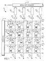
- the charge injection imaging device of this invention comprising a two-dimensional array of photosensitive elements 12 arranged in rows R1 - R4 and columns C1 - C4.
- Each of the photosensitive elements 12 comprises a row electrode 14 and a column electrode 16 disposed on a silicon substrate so as to store photogenerated charges 18 in potential wells under the electrodes in a manner as is well known in the art.
- the row electrodes 14 of each row are commonly interconnected by row lines 14 R1 - 14 R4.
- the electrodes 16 of each column are commonly connected by column lines 16 C1 - 16 C4.
- FIG. 1 shows only a four photosensitive element by four photosensitive element array, in actual practice such imaging arrays comprise a substantially greater number of photosensitive elements.
- the row electrode interconnect lines 14 R1 - 14 R4 are controlled by a row scan circuit 19 in a manner as to be more fully described in the following discussion.
- the column electrode interconnect lines 16 C1 - 16 C4 connect, respectively, to amplifier circuits 201 - 204 which operate in the manner of this invention to be hereinafter described.
- the output signals from amplifiers 201 - 204 are, in turn, directed to respective storage lines 221 - 224, the operation of which will again be described in substantially more detail in the following discussion.
- the storage lines 221 - 224 output signals to a serial shift register 24 which provides a continuous stream of electronic information signals corresponding to image data derived from each photosensitive element 12 in succeeding order along each succeeding row.
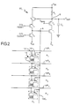
- the amplifier circuit 201 comprises a pair of MOS field effect transistors T1 and T2 connected in cascaded relationship with respect to each other.
- the input to the amplifier circuit 201 from the column electrode, interconnect line 16 C1 as shown at node A connects to the gate electrode of transistor T1.
- the drain and source electrodes of transistors T1 and T2, respectively, are in common connection with respect to each other while the source electrode of transistor T1 connects to a constant low voltage source V S .
- the gate electrode to the transistor T2 connects to a control voltage V BIAS which controls the amplifier in the manner of this invention to be subsequently described wherein
- the drain electrode of transistor T2 connects to a node B which, in turn, defines the output terminal for the amplifier at Vout.
- the transistors T2 and T1 are in serial connection with a load resistor R L and in parallel connection with an output capacitor C0.
- the load resistor R L connects to a steady state high voltage source V DD .
- the output capacitor C0 and load resistor R L cooperate to limit the bandwidth of the amplifier circuit 201.
- the amplifier circuit 201 also includes means for resetting the voltage level at node A comprising two MOS field effect transistors T3 and T4 connected in cascade relationship with respect to each other.
- the source and drain electrodes of the transistors T3 and T4, respectively, are in common connection with respect to each other.
- the gate electrode to the transistor T3 is in common connection with the node B and hence, the output terminal V out while the drain electrode of transistor T3 connects to the high steady state voltage source V DD .
- the gate electrode to the transistor T4 in turn, connects to a control voltage which varies in the manner of this invention to be subsequently described.
- the source electrode of the transistor T4 is in common connection to the node A and the electrode common interconnect line 16 C1.
- the amplifier 201 also includes means for clearing the node A comprising an MOS field effect transistor T5 having its drain electrode connecting to the node A and the column electrode common interconnect line 16 C1 and its source electrode connecting to a low steady state voltage source V SS .
- the gate electrode to the transistor T5 connects to a control voltage which is varied in the manner of this invention to be subsequently described herein.
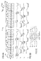
- FIG. 3A there is shown in substantial detail the storage line 221 comprising an input stage 26 in serial connection with a plurality of succeeding serially connected charge coupled device (CCD) storage stages 281 - 28 n .
- CCD charge coupled device
- Each of the CCD storage stages 281 - 28 n comprises four succeeding storage areas or phases ( ⁇ 1 - ⁇ 4). Charges corresponding to image and noise defining electronic information signals are advanced through succeeding phases of each succeeding stage 281 - 28 n in a sequential manner by transfer gates or electrodes (not shown) which are sequentially energized in a well-known manner.
- the transfer gates or electrodes 301 - 304 are in common connection with respect to each other and retrieve image and noise defining electronic information signals from the storage line 221 in the manner of this invention as will be subsequently described herein.
- the first two transfer electrodes 301 and 302 connect, respectively, to the fourth phase ⁇ 4 of the first storage stage 281 and the second phase ⁇ 2 of the third storage stage 283.
- the last two transfer gates 303 and 304 connect, respectively, to the fourth phase ⁇ 4 of the third from the last storage stage 28 n-2 and the second phase ⁇ 2 of the last storage stage 28 n .
- the input bias to the commonly connected transfer electrodes 301 - 304 is controlled by way of an MOS field effect transistor T6 having a drain electrode connected to a high steady state voltage source V BIAS and a gate electrode connected to a variable control voltage V RES .
- image defining scene light is allowed to impinge during an exposure interval upon the photosensitive elements 12 so as to photogenerate charges 18 in potential wells under the row and column electrodes 14 and 16 as is well known in the art.
- both the row and column electrodes of all of the photosensitive elements 12 are energized to a high voltage level by way of the row electrode common interconnect lines 14 R1 - 14 R4 and the column electrode common interconnect lines 16 C1 - 16 C4 in a manner as is well known in the art.
- potential wells under the row electrodes 14 are deeper so that photogenerated charges 18 are stored under the row electrodes 14 as shown in the drawings.
- the charges stored in the photosensitive elements 12 in each of the columns (C1 - C4) are simultaneously read out for all the photosensitive elements 12 in each succeeding row starting with the first row R1.
- the following description is limited primarily to the operation of only one amplifier 201 and one storage line 221, it will be readily understood that all the amplifiers 201 - 204 and all the storage lines 221 - 224 operate simultaneously and in the identical manner.
- the column electrodes 16 are reset to the voltage level of node B by applying a high voltage (binary logic 1) input signal to the gate electrode of transistor T4, thereby establishing gain stabilization.
- the transistor T4 is turned off by applying a low voltage (binary logic 0) input signal to its gate electrode.
- the voltage level of node A contains noise due to the fluctuation of the voltage across reset transistor T4. This noise is KTC noise as previously discussed and ultimately will be cancelled in the manner of this invention.
- the row R1 electrodes 14 are thereafter set to a low voltage level by the row scan circuit 19 applying the appropriate low voltage to the row electrode common interconnect line 14 R1.
- the charge stored under the row R1 electrodes 14, in turn, is transferred to the corresponding column electrodes 16 in the row R1.
- the charges transferred into the column electrodes 16 in this manner cause the voltage or signal level at node A in each of the column electrode common interconnect lines 16 C1 - 16 C4 to change by an amount proportional to the size of the charge transferred thereto.
- This change in voltage at node A is amplified by the transistors T2 and T1 to provide an amplified output voltage at node B.
- the changed voltage at node B corresponds to both image and noise defining electronic information signals including KTC noise induced at each one of the column electrode common interconnect lines 16 C1 - 16 C4 by the corresponding one of reset transistors T4 and T3 and fixed pattern noise resulting from the variations in the crossing of the row electrode common interconnect lines 14 R1 - 14 R4 with the column electrode common interconnect lines 16 C1 - 16 C4.
- the signal level at node B is repeatedly sampled a determinate number of times. During each sample time, a charge representing the signal is created and stored in the input stage 26 of the storage line 221. Thus, at the end of the sampling period a large charge composed of a plurality of small charges corresponding to each sample is present in the input stage 26 of the storage line 221.
- This sampling process enables the bandwidth of each amplifier to be substantially reduced without increasing the size of the storage capacitor C0 and load resistor R L . In this manner, the amplifier circuits 201 - 204 can be maintained within the narrow pitch of each of the columns C1 - C4.
- the row scan circuit 19 next operates to apply a high voltage to the row electrodes 14 in the row R1 thereby affecting the transfer of the charges under the column electrodes 16 back into the row R1 electrodes 14.
- the signal level at node B is again sampled in the aforementioned manner and stored in the input stage 26 of the storage line 221.
- This last sampled signal contains KTC noise.
- the previously transferred image and noise defining electronic information signal is successively advanced from the input stage 26 to the first storage area or phase ⁇ 1 of the first storage stage 281.
- first electronic information signals corresponding to the image, KTC noise, and fixed pattern noise and second electronic information signals corresponding to the KTC noise are successively transferred, respectively, into two succeeding stages of the storage line 221.
- the row R1 electrodes 14 are set to a low voltage by turning on transistor T5. In this manner, the row R1 photosensitive elements 12 are cleared of charge since both the row electrodes 14 and the column electrodes 16 are simultaneously set to a low voltage.
- the row R1 electrodes 14 are subsequently brought back to a high voltage level in concert with the aforementioned turning off of all the T5 transistors. Resetting all the column electrode 16 voltages to the voltage level at each respective node B in the aforementioned manner by turning on all the T4 transistors, as will be readily understood, also operates to set the column electrodes 16 of the row R1 of photosensitive elements to a high voltage level.
- the row scan circuit 19 operates to set the row electrodes 14 of the first row R1 of photosensitive elements 12 to a low voltage.
- the four photosensitive elements 12 of row R1 are cleared of signal charge so that the signal transfer to respective ones of the node A by way of respective ones of the column interconnect lines 16 C1 - 16 C4 defines the fixed pattern noise for respective ones of the photosensitive elements 12 of row R1.
- fixed pattern noise defining electronic information signals for each photosensitive element 12 of row R1 are transferred outside of the succeeding order in which image and KTC noise defining electronic information signals are transferred for the photosensitive elements of row R1.
- the fixed pattern noise defining electronic information signals for the photosensitive elements 12 of R1 are transferred in sequence with the transfer of image and KTC noise defining electronic information signals for the photosensitive elements 12 of row R4.
- the signal level at node A is subsequently amplified in the aforementioned manner to provide an amplified output electronic information signal at node B corresponding to the fixed pattern noise.
- the fixed pattern noise defining electronic information signal is thereafter sampled and transferred in the aforementioned manner to the input stage 26 of the storage line 221.
- the previously transferred image and KTC noise defining electronic information signals for the photosensitive elements of row R1 are successively advanced in correspondence with the transfer of image and noise defining electronic information signals from the three succeeding rows R2, R3 and R4 along succeeding storage areas or phases of the storage line 221.
- three succeeding electronic information signals for each photosensitive element 12 are provided in ordered spaced apart sequence from the amplifier 201 to the storage line 221.
- three spaced apart electronic information signals are provided for each row R1 photosensitive element wherein the first signal corresponds to image defining scene light incident to the row R1 photosensitive element together with the KTC and fixed pattern noise associated with the row R1 photosensitive element, and the second signal which immediately succeeds the first signal corresponds to the KTC noise associated with the row R1 photosensitive element.
- the third signal which succeeds the transfer of signals from the row R4 photosensitive element corresponds to the fixed pattern noise associated with the row R1 photosensitive element.
- this ordered sequence for the transfer of electronic information signals although described only for the first row R1 photosensitive elements is sequentially repeated for the photosensitive elements of all the succeeding rows R2 - R4.
- Electrodes or gates associated with the various storage areas or phases operate in a well-known manner to advance the aforementioned succeeding electronic information signals along the storage stages 281 - 28 n until reaching the positions as shown at t1 in FIG. 3B.
- the first image defining electronic information signal including the KTC and fixed pattern noise first transferred from the amplifier 201 to storage line 221 is advanced to the fourth phase ⁇ 4 of storage stage 28 n-1 as shown at SIG1.
- the second succeeding electronic information signal corresponding to the KTC noise is advanced to the fourth phase ⁇ 4 of storage stage 28 n-2 as shown at KTC1. It is readily apparent that this pattern is repeated for each succeeding photosensitive element 12 until reaching the electronic information signal for the KTC noise for the 4 th photosensitive element 12 as stored in the fourth phase ⁇ 4 of the storage stage 282 and shown at KTC4.
- the next succeeding electronic information signal stored in the fourth phase ⁇ 4 of storage stage 281 corresponds to the fixed pattern noise for the first photosensitive element 12 to which the image defining electronic information signal SIG1 and the KTC1 correspond.
- the control voltages to the four phases change in a time interval from t1 to t2 as shown in FIG. 3C to advance the charges along the storage stages 201 through 28 n as shown in line t2 of FIG. 3B.
- the phase electrode control voltages change as shown in FIG. 3C to advance the charges to the position as shown at line t3 in FIG. 3B.
- the image and noise defining electronic information signal (SIG1) is located in the second phase ⁇ 2 of storage stage 28 n adjacent transfer electrode 304.
- the fourth phase ⁇ 4 of storage stage 28 n-2 under transfer electrode 303 has just been cleared of KTC defining electronic information signals (KTC1) so as to leave a signal level corresponding to the negative value of the KTC defining electronic information signal (-KTC1).
- KTC1 KTC defining electronic information signals
- KTC4 for the fourth succeeding photosensitive element 12 in the respective column can be seen to be advanced to the second phase ⁇ 2 of the storage stage 283 under transfer electrode 302.
- the fourth phase ⁇ 4 of the storage stage 281 under transfer electrode 301 has just been cleared of the fixed pattern noise defining electronic information signal (FPN1) so as to leave a signal level corresponding to the negative value of the fixed pattern noise defining electronic information signal (-FPN1).
- the KTC noise defining electronic information signal (KTC1) and a fixed pattern noise defining electronic information signal (FPN1) are located, respectively, under the third and first floating transfer gates 303 and 301.
- the storage areas or phases under the second and fourth floating transfer gates 302 and 304, respectively, are clear of charge.
- the floating transfer gates 301 - 304 are set to a high signal level V BIAS by transistor T6 on through control voltage V RES .
- Transistor T6 is thereafter turned off so as to allow the transfer gates 301 through 304 to float at the aforesaid high signal V BIAS .
- the charges corresponding to KTC defining electronic information signals (KTC1) and the fixed pattern noise defining electronic information signals (FPN1) are transferred from the third and first floating transfer gates 303 and 301, respectively, offsetting the voltage at which the gates are floated.
- the image and noise defining electronic information signal (SIG1) and the KTC noise defining electronic information signal (KTC4) are transferred to the fourth and second transfer gates 304, 302, respectively, adding to the signal level at which the transfer gates are floated. In this manner an image defining electronic information signal is automatically provided at the common node of the transfer gates 301 through 304 from which KTC noise defining electronic information signals and fixed pattern noise defining electronic information signals are automatically cancelled.
- the fixed pattern noise defining electronic information signals are sensed from each photoresponsive element in each respective column after the charge has been cleared from the next three succeeding photoresponsive elements in each respective column.
- the fixed pattern noise defining electronic information signals are sensed from the photoresponsive elements 12 outside the succeeding order in which the image and KTC noise defining electronic information signals are sensed from the photosensitive elements.
- the fixed pattern noise defining electronic information signals are sensed from the photosensitive elements 12 in correlation with the sensing of image and KTC noise defining electronic information signals for photosensitive elements spaced apart therefrom by three photosensitive elements along their respective columns.
- the fixed pattern noise defining electronic information signal (FPN1) sensed after the fourth photoresponsive element also inherently includes KTC noise defining electronic information signals for the fourth photoresponsive element.
- KTC4 the transfer of the KTC noise defining electronic information signal (KTC4) for the fourth photoresponsive element transferred to the second floating transistor electrode 302 is offset by its identical component which forms an inherent part of the fixed pattern noise defining electronic information signal (FPN1) subtracted from the signal level of the first floating transfer electrode 301.
- the signal level at the common node between the floating transfer electrodes 301 through 304 thus provides an image defining electronic information signal in ordered sequence for each succeeding photosensitive element 12 from which both the KTC and fixed pattern noise defining electronic information signals are automatically offset.
- This image defining electronic information signal is amplified by the amplifier 32 and output at terminal V out to the serial shift register 24 which operates in a well-known manner to provide a continuous stream of image defining electronic information signals for each succeeding photosensitive element in each row.
- the invention herein described is by no means limited to the above-described order in which the image and noise defining electronic information signals are transferred from the photosensitive elements provided that the fixed pattern noise defining electronic information signals are transferred only after the next three succeeding rows of photosensitive elements are cleared of charge.
Landscapes
- Engineering & Computer Science (AREA)
- Multimedia (AREA)
- Signal Processing (AREA)
- Transforming Light Signals Into Electric Signals (AREA)
- Solid State Image Pick-Up Elements (AREA)
- Picture Signal Circuits (AREA)
Claims (10)
- CID-Element mit den folgenden Merkmalen:
ein Feld lichtempfindlicher Elemente (12), von denen alle mit elektronischen Informationssignalen behaftet sind, die ein Rauschen definieren, wobei die lichtempfindlichen Elemente elektronische Informationssignale gemäß dem einfallenden Szenenlicht erzeugen, die das Bild definieren;
Mittel (16; 20) zur Übertragung und Verstärkung der das Bild und das Rauschen definierenden elektronischen Informationssignale aus dem Feld lichtempfindlicher Elemente (12) in einer selektiv gewählten Ordnungsfolge;
mehrere seriell verbundene Speicherelemente (22), die die das Bild und das Rauschen definierenden elektronischen Informationssignale in der gewählten Ordnungsfolge empfangen, wobei jedes Speicherelement (22) das Bild und/oder das Rauschen definierende elektronische Informationssignale entsprechend einem der lichtempfindlichen Elemente (12) des Feldes speichert;
Mittel zum Verschieben der das Bild und das Rauschen definierenden elektronischen Informationssignale durch die seriell verbundenen Speicherelemente in einer solchen Weise, daß jedes der Speicherelemente jeweils eines der das Bild und/oder das Rauschen definierenden elektronischen Informationssignale für jedes lichtempfindliche Element während eines vorbestimmten Zeitintervalls speichert; und
Mittel zur gleichzeitigen Wiedergewinnung gewählter, das Bild und das Rauschen definierende elektronische Informationssignale aus ausgewählten seriell verbundenen Speicherelementen (22) zu vorgewählten aufeinanderfolgenden bestimmten Zeitintervallen, um das Bild definierende elektronische Informationssignale für jedes der aufeinanderfolgenden lichtempfindlichen Elemente zu schaffen, aus denen die das Rauschen definierenden elektronischen Informationssignale automatisch ausgelöscht sind. - CID-Element nach Anspruch 1, bei welchem:
das Feld lichtempfindlicher Elemente (12) ein zweidimensionales Feld lichtempfindlicher Elemente ist, die in Zeilen (R) und Reihen (C) angeordnet sind;
die Mittel zur Übertragung (16) und Verstärkung (20) der das Bild und das Rauschen definierenden elektronischen Informationssignale eine gleichzeitige Übertragung der das Bild und/oder das Rauschen definierenden elektronischen Informationssignale für jedes lichtempfindliche Element (12) einer jeden Zeile (R) des Feldes bewirken, und sie bewirken außerdem eine Übertragung der das Bild und/oder das Rauschen definierenden elektronischen Informationssignale in einer aufeinanderfolgenden Ordnung für jedes lichtempfindliche Element (12) längs jeder Reihe (C), wobei ein Teil der das Rauschen definierenden elektronischen Informationssignale für jedes lichtempfindliche Element (12) außerhalb der aufeinanderfolgenden Ordnung in Korrelation mit der Übertragung der das Bild und das Rauschen definierenden elektronischen Informationssignale für die lichtempfindlichen Elemente (12) übertragen wird, und zwar im Abstand hierzu längs der jeweiligen Reihen (C);
die in Reihe geschalteten Speicherelemente (22) so gestaltet sind, daß sie gleichzeitig die das Bild und/oder das Rauschen definierenden elektronischen Informationssignale für jedes lichtempfindliche Element in jeder Zeile (R) speichern, und zwar in jener Ordnung, in der die Signale von ihren jeweiligen Reihen (C) übertragen sind;
die das Vorschieben bewirkenden Mittel gleichzeitig die das Bild und/oder das Rauschen definierenden elektronische Informationssignale für jedes lichtempfindliche Element (12) in jeder Zeile (R) in der Ordnungsfolge vorschieben, in der die Signale von ihren jeweiligen Reihen (C) längs der seriell geschalteten Speicherelemente (12) übertragen werden; und
die Mittel zur Wiedergewinnung eine Einrichtung aufweisen, um gleichzeitig die das Bild und/oder das Rauschen definierenden elektronischen Informationssignale für jedes lichtempfindliche Element in jeder Zeile in einer Ordnungsfolge aus ihren jeweiligen Reihen wiedergewinnen, und zwar einschließlich jener Teile der das Rauschen definierenden elektronischen Informationssignale, die außerhalb der Ordnungsfolge übertragen wurden. - CID-Element nach Anspruch 2, bei welchem die Speicherelemente (28) mehrere seriell geschaltete ladungsgekoppelte Stufen (CCD-Stufen) aufweisen, von denen jede Stufe eine gewählte Zahl bestimmter Speicherplätze (φ1 bis φ4) aufweist, durch die der Vorschub der das Bild und/oder das Rauschen definierenden elektronischen Informationssignale durch die selektive sequentielle Erregung einer ersten Mehrzahl von Elektroden (36) gesteuert wird, die den jeweils ersten Stufen (28) zugeordnet sind, wobei die Mittel zur gleichzeitigen Wiedergewinnung gewählter, das Bild und/oder das Rauschen definierender elektronischer Informationssignale eine zweite Mehrzahl von Elektroden umfaßt, die miteinander verbunden sind und jeweils einem der getrennten Speicherplätze (φ1 bis φ4) zugeordnet sind.
- CID-Element nach Anspruch 2, bei welchem die Mittel zur gleichzeitigen Wiedergewinnung gewählter, das Bild und/oder das Rauschen definierender elektronischer Informationssignale außerdem Steuermittel (T₆) aufweisen, um den Signalpegel der gemeinsamen Verbindung zwischen der zweiten Mehrzahl von Elektroden (30) auf einen gewählten Pegel einzustellen, unmittelbar bevor die gewählten aufeinanderfolgenden Zeitintervalle ablaufen, während denen die gewählten, das Bild und/oder das Rauschen definierenden elektronischen Informationssignale wiedergewonnen werden, worauf die gemeinsame Verbindung während des gewählten folgenden vorbestimmten Zeitintervalls gepuffert wird.
- CID-Element nach Anspruch 3, bei welchem die Mittel zur Übertragung und Verstärkung der das Bild und/oder das Rauschen definierenden elektronischen Informationssignale eine Übertragung eines ein Bild und ein Rauschen definierenden elektronischen Informationssignals bewirkt, und zwar entsprechend dem einfallenden Szenenlicht, dem KTC-Rauschen, während ein das KTC-Rauschen definierendes elektronisches Informationssignal in einer Ordnungsfolge für jedes lichtempfindliche Element (12) in ihren jeweiligen Reihen (C) und ein das Festmuster-Rauschen definierendes elektronisches Informationssignal entsprechend jedem aufeinanderfolgenden lichtempfindlichen Element (12) außerhalb der Ordnungsfolge übertragen werden, wobei der Speicher (22) das das Bild und das Rauschen definierende elektronische Informationssignal, das das KTC-Rauschen definierende elektronische Informationssignal und das das Festmuster-Rauschen definierende elektronische Informationssignal in einer gewählten Aufeinanderfolge der Speicherplätze (φ1 bis φ4) der seriell geschalteten CCD-Stufen speichert, und wobei die Verschiebemittel das das Bild und das Rauschen definierende elektronische Informationssignal, das das KTC-Rauschen definierende elektronische Informationssignal und das das Festmuster-Rauschen definierende elektronische Informationssignal durch die seriell geschalteten Speicherelemente (28) vorschiebt, und wobei die Mittel zur Wiedergewinnung gleichzeitig für jedes aufeinanderfolgende lichtempfindliche Element (12) das das Bild und das Rauschen definierende elektronische Informationssignal und das das KTC-Rauschen definierende elektronische Informationssignal und das das Festmuster-Rauschen definierende elektronische Informationssignal für jenes lichtempfindliche Element (12) in einer solchen Weise wiedergewinnen, daß ein das Bild definierendes elektronisches Informationssignal für jedes aufeinanderfolgende lichtempfindliche Element geschaffen wird, welches weder die das KTC-Rauschen definierenden elektronischen Informationssignale noch die das Festmuster-Rauschen definierenden elektronischen Informationssignale enthält.
- CID-Element nach Anspruch 2, bei welchem das Feld lichtempfindlicher Elemente (12) eine Reihenelektrode (16) und eine Zeilenelektrode (14) für jedes lichtempfindliche Element (12) zusammen mit Mitteln (16R; 14C) aufweist, um eine gemeinsame Verbindung zwischen sämtlichen Elektroden in jeder Reihe (C) und jeder Zeile (R) herzustellen, wobei die Mittel zur Übertragung und Verstärkung der das Bild und/oder das Rauschen definierenden elektronischen Informationssignale einer Verstärkeranordnung (20) zur Verstärkung der das Bild und/oder das Rauschen definierenden elektronischen Informationssignale aus jeder der Reihen (C) der gemeinsamen Elektroden (16) bewirken, wobei Rücksetzmittel (T₃, T₄) den Signalpegel einer jeden der in den Reihen gemeinsam verbundenen Elektroden auf vorbestimmte hohe Signalpegel zu vorgewählten Zeiten setzen, und Löschmittel (T₅) den Signalpegel jeder Reihe (C) der gemeinsamen Elektroden (16) auf einen vorbestimmten niedrigen Signalpegel zu vorgewählten Zeiten setzen.
- CID-Element nach Anspruch 6, welches Abtastmittel aufweist, die betriebsmäßig den Mitteln zur Verstärkung und Speicherung zugeordnet sind, um wiederholt den Signalpegelausgang des Verstärkers abzutasten und den Gesamtwert des wiederholt abgetasteten Signalpegels in den ersten der seriell verbundenen Speicherelemente (28) zwecks Speicherung einzugeben, so daß die Bandbreite des Verstärkers (20) verringert wird.
- CID-Element nach Anspruch 7, bei welchem der Verstärker (20) für jede Reihe zwei MOS-Feldeffekt-Transistoren (T₁, T₂) aufweist, die in Kaskade zueinander geschaltet sind, wobei das Gatter des einen Transistors (T₁) der zwei MOS-Feldeffekt-Transistoren mit jeweils einer der miteinander verbundenen Reihenelektroden (16) verbunden ist, wobei die beiden MOS-Feldeffekt-Transistoren außerdem in Reihe mit einem Lastwiderstand (RL) und parallel zu einem Ausgangskondensator (Co) geschaltet sind, und wobei der Lastwiderstand (RL) und der Ausgangswiderstand (C₀) zusammenwirken, um die Bandbreite des Verstärkers (20) zu begrenzen.
- CID-Element nach Anspruch 8, bei welchem die Rücksetzmittel zum Setzen des Signalpegels der gemeinsam miteinander verbundenen Elektroden (16) der Reihen (C) für jede Reihe ein weiteres Paar von MOS-Feldeffekt-Transistoren (T₃, T₄) aufweisen, die in Kaskade zueinander geschaltet sind, wobei die Drainelektrode des einen Transistors (T₄) der MOS-Feldeffekt-Transistoren (T₃, T₄) des anderen Paares von Rücksetztransistoren an die den Reihen gemeinsame Elektroden (16) angeschlossen sind, während die Gatterelektrode des anderen Transistors (T₃) der MOS-Feldeffekt-Transistoren des anderen Paares an die gemeinsame Verbindung zwischen Lastwiderstand (RL), Ausgangskondensator (C₀) und Quellelektrode des anderen Transistors (T₂) der MOS-Feldeffekt-Transistoren des Paares von Verstärkertransistoren (T₁, T₂) angeschaltet ist.
- CID-Element nach Anspruch 9, bei welchem die Löschmittel zum Setzen des Signalpegels für jede Reihe (C) der miteinander verbundenen Elektroden (12) auf einen vorbestimmten niedrigen Signalpegel für jede Reihe einen MOS-Feldeffekt-Transistor (T₅) aufweisen, dessen Quellelektrode mit den gemeinsam verbundenen Reihenelektroden (16) in Verbindung steht, während seine Drainelektrode mit einer Spannungsquelle (VSS) in Verbindung steht, die den vorbestimmten niedrigen Signalpegel liefert.
Applications Claiming Priority (2)
| Application Number | Priority Date | Filing Date | Title |
|---|---|---|---|
| US170938 | 1988-03-21 | ||
| US07/170,938 US4843473A (en) | 1988-03-21 | 1988-03-21 | Charge injection device with low noise readout |
Publications (3)
| Publication Number | Publication Date |
|---|---|
| EP0334058A2 EP0334058A2 (de) | 1989-09-27 |
| EP0334058A3 EP0334058A3 (de) | 1992-05-06 |
| EP0334058B1 true EP0334058B1 (de) | 1995-05-24 |
Family
ID=22621886
Family Applications (1)
| Application Number | Title | Priority Date | Filing Date |
|---|---|---|---|
| EP89103500A Expired - Lifetime EP0334058B1 (de) | 1988-03-21 | 1989-02-28 | Ladungsinjektionsbauelement mit rauscharmer Ausgabe |
Country Status (5)
| Country | Link |
|---|---|
| US (1) | US4843473A (de) |
| EP (1) | EP0334058B1 (de) |
| JP (1) | JPH0211073A (de) |
| CA (1) | CA1322045C (de) |
| DE (1) | DE68922770T2 (de) |
Cited By (1)
| Publication number | Priority date | Publication date | Assignee | Title |
|---|---|---|---|---|
| DE102009049201A1 (de) * | 2009-10-13 | 2011-04-28 | Arnold & Richter Cine Technik Gmbh & Co. Betriebs Kg | Bildsensor und Betriebsverfahren |
Families Citing this family (8)
| Publication number | Priority date | Publication date | Assignee | Title |
|---|---|---|---|---|
| EP0400985B1 (de) * | 1989-05-31 | 2000-08-23 | Canon Kabushiki Kaisha | Fotoelektrischer Umwandler |
| US5047863A (en) * | 1990-05-24 | 1991-09-10 | Polaroid Corporation | Defect correction apparatus for solid state imaging devices including inoperative pixel detection |
| JP3544084B2 (ja) * | 1996-12-10 | 2004-07-21 | シャープ株式会社 | 増幅型固体撮像装置 |
| DE69841597D1 (de) * | 1997-09-22 | 2010-05-20 | Cypress Semiconductor Corp Bel | Verfahren und vorrichtungen zur verbesserung der bildqualität in einem bildsensor |
| US5981932A (en) * | 1997-11-05 | 1999-11-09 | Stmicroelectronics, Inc. | Noise compensation circuit for image sensors |
| US6128039A (en) * | 1999-01-11 | 2000-10-03 | Omnivision Technologies, Inc. | Column amplifier for high fixed pattern noise reduction |
| JP2000287130A (ja) * | 1999-03-31 | 2000-10-13 | Sharp Corp | 増幅型固体撮像装置 |
| US8476567B2 (en) | 2008-09-22 | 2013-07-02 | Semiconductor Components Industries, Llc | Active pixel with precharging circuit |
Family Cites Families (27)
| Publication number | Priority date | Publication date | Assignee | Title |
|---|---|---|---|---|
| US3965368A (en) * | 1974-10-24 | 1976-06-22 | Texas Instruments Incorporated | Technique for reduction of electrical input noise in charge coupled devices |
| US4064533A (en) * | 1975-10-24 | 1977-12-20 | Westinghouse Electric Corporation | CCD focal plane processor for moving target imaging |
| JPS5850030B2 (ja) * | 1979-03-08 | 1983-11-08 | 日本放送協会 | 光電変換装置およびそれを用いた固体撮像板 |
| DE2936703A1 (de) * | 1979-09-11 | 1981-03-26 | Siemens AG, 1000 Berlin und 8000 München | Monolithisch integrierte schaltung mit einem zweidimensionalen bildsensor |
| DE2939490A1 (de) * | 1979-09-28 | 1981-04-16 | Siemens AG, 1000 Berlin und 8000 München | Monolithisch integrierter zweidimensionaler bildsensor mit einer differenzbildenden stufe |
| FR2481553A1 (fr) * | 1980-04-23 | 1981-10-30 | Thomson Csf | Dispositif photosensible lu par transfert de charges et camera de television comportant un tel dispositif |
| US4316221A (en) * | 1980-08-05 | 1982-02-16 | General Electric Company | Apparatus for sequential row injection readout of CID imagers |
| JPS5738073A (en) * | 1980-08-20 | 1982-03-02 | Hitachi Ltd | Solid-state image sensor |
| US4392157A (en) * | 1980-10-31 | 1983-07-05 | Eastman Kodak Company | Pattern noise reduction method and apparatus for solid state image sensors |
| JPS57120272A (en) * | 1981-01-14 | 1982-07-27 | Victor Co Of Japan Ltd | Reproducing device for discoid information recording medium |
| US4389674A (en) * | 1981-03-05 | 1983-06-21 | Leeds & Northrup Company | Preamplifier for low voltage signals in the presence of high voltage noise |
| US4466018A (en) * | 1981-05-09 | 1984-08-14 | Sony Corporation | Image pickup apparatus with gain controlled output amplifier |
| JPS5884568A (ja) * | 1981-11-13 | 1983-05-20 | Fuji Xerox Co Ltd | 原稿読取装置 |
| JPS58156272A (ja) * | 1982-03-12 | 1983-09-17 | Sony Corp | スミア補正回路 |
| JPS58157262A (ja) * | 1982-03-15 | 1983-09-19 | Hitachi Ltd | 固体撮像装置 |
| JPS58169965A (ja) * | 1982-03-31 | 1983-10-06 | Hitachi Ltd | 固体撮像装置 |
| US4556851A (en) * | 1983-08-22 | 1985-12-03 | Rca Corporation | Reduction of noise in signal from charge transfer devices |
| JPS6086981A (ja) * | 1983-10-18 | 1985-05-16 | Toshiba Corp | 固体撮像装置 |
| JPS60112376A (ja) * | 1983-11-22 | 1985-06-18 | Sanyo Electric Co Ltd | 撮像装置 |
| US4556910A (en) * | 1984-01-05 | 1985-12-03 | Fuji Photo Film Co., Ltd. | Image sensing device having on-chip fixed-pattern noise reducing circuit |
| JPS60150384A (ja) * | 1984-01-18 | 1985-08-08 | Hitachi Ltd | 固体撮像装置 |
| US4608606A (en) * | 1984-03-15 | 1986-08-26 | Rca Corporation | CCD floating-element output stages providing low reset noise with single sampling |
| FR2571572B1 (fr) * | 1984-10-09 | 1987-01-02 | Thomson Csf | Dispositif photosensible a transfert de ligne muni d'amplificateurs de contre-reaction |
| US4584609A (en) * | 1985-04-15 | 1986-04-22 | Rca Corporation | Parallel-input/serial output CCD register with clocking noise cancellation, as for use in solid-state imagers |
| US4689808A (en) * | 1986-01-31 | 1987-08-25 | Rca Corporation | Low noise signal detection for a charge transfer device by quadrature phasing of information and reset noise signals |
| US4644287A (en) * | 1986-03-10 | 1987-02-17 | Rca Corporation | Low noise synchronous detection for a charge transfer device |
| JPS6328167A (ja) * | 1986-07-22 | 1988-02-05 | Fuji Xerox Co Ltd | イメ−ジセンサの駆動装置 |
-
1988
- 1988-03-21 US US07/170,938 patent/US4843473A/en not_active Expired - Lifetime
-
1989
- 1989-02-28 EP EP89103500A patent/EP0334058B1/de not_active Expired - Lifetime
- 1989-02-28 DE DE68922770T patent/DE68922770T2/de not_active Expired - Fee Related
- 1989-03-06 CA CA000592866A patent/CA1322045C/en not_active Expired - Fee Related
- 1989-03-20 JP JP1069143A patent/JPH0211073A/ja active Pending
Cited By (2)
| Publication number | Priority date | Publication date | Assignee | Title |
|---|---|---|---|---|
| DE102009049201A1 (de) * | 2009-10-13 | 2011-04-28 | Arnold & Richter Cine Technik Gmbh & Co. Betriebs Kg | Bildsensor und Betriebsverfahren |
| US8531566B2 (en) | 2009-10-13 | 2013-09-10 | Arnold & Richter Cine Technik Gmbh & Co., Betriebs Kg | Image sensor and operating method |
Also Published As
| Publication number | Publication date |
|---|---|
| DE68922770D1 (de) | 1995-06-29 |
| CA1322045C (en) | 1993-09-07 |
| EP0334058A3 (de) | 1992-05-06 |
| JPH0211073A (ja) | 1990-01-16 |
| DE68922770T2 (de) | 1995-09-28 |
| US4843473A (en) | 1989-06-27 |
| EP0334058A2 (de) | 1989-09-27 |
Similar Documents
| Publication | Publication Date | Title |
|---|---|---|
| EP0493455B1 (de) | I.c. sensor | |
| US3904818A (en) | Removal of dark current spikes from image sensor output signals | |
| EP0908957B1 (de) | Bildaufnahme-, Signaldetektion- und Signalakkumulierungsvorrichtung | |
| US5296696A (en) | Solid state image pickup apparatus and driving method | |
| EP0809300B1 (de) | Bildsensor mit aktiven Bildelementen mit Einzelbildrücksetzung | |
| US4336557A (en) | Monolithically integrated circuit for relatively slow readout from a two-dimensional image sensor | |
| USRE34908E (en) | 3-transistor source follower-per-detector unit cell for 2-dimensional focal plane arrays | |
| US7154548B2 (en) | Multiplexed and pipelined column buffer for use with an array of photo sensors | |
| EP2378764A2 (de) | Halbleiterbauelement und Steuerungsverfahren und Vorrichtung zur Ansteuerung einer Einheitenkomponente des Halbleiterbauelements | |
| US4445117A (en) | Transistorized focal plane having floating gate output nodes | |
| US4617593A (en) | Visible and near infrared imaging system | |
| US6515702B1 (en) | Active pixel image sensor with a winner-take-all mode of operation | |
| EP0334058B1 (de) | Ladungsinjektionsbauelement mit rauscharmer Ausgabe | |
| US4744057A (en) | Multilinear charge transfer array | |
| US5600369A (en) | Large-sized pixel image detector | |
| EP0302675B1 (de) | Photoelektrisches Umwandlungsgerät | |
| US20060103748A1 (en) | Solid state imaging apparatus | |
| US4628364A (en) | Two-dimensional semiconductor image sensor including an arrangement for reducing blooming | |
| US4316221A (en) | Apparatus for sequential row injection readout of CID imagers | |
| US4109284A (en) | Self-scanning photo-sensitive circuits | |
| US4162411A (en) | Charge transfer analog processing apparatus for serial-to-parallel conversion | |
| US4514821A (en) | Electro-optical CCD transversal filter with analog reference weights | |
| US4752829A (en) | Multipacket charge transfer image sensor and method | |
| US5091922A (en) | Charge transfer device type solid state image sensor having constant saturation level | |
| KR100342092B1 (ko) | 이미지 센서 |
Legal Events
| Date | Code | Title | Description |
|---|---|---|---|
| PUAI | Public reference made under article 153(3) epc to a published international application that has entered the european phase |
Free format text: ORIGINAL CODE: 0009012 |
|
| AK | Designated contracting states |
Kind code of ref document: A2 Designated state(s): DE FR GB NL |
|
| PUAL | Search report despatched |
Free format text: ORIGINAL CODE: 0009013 |
|
| AK | Designated contracting states |
Kind code of ref document: A3 Designated state(s): DE FR GB NL |
|
| 17P | Request for examination filed |
Effective date: 19921019 |
|
| 17Q | First examination report despatched |
Effective date: 19940502 |
|
| GRAA | (expected) grant |
Free format text: ORIGINAL CODE: 0009210 |
|
| AK | Designated contracting states |
Kind code of ref document: B1 Designated state(s): DE FR GB NL |
|
| ET | Fr: translation filed | ||
| REF | Corresponds to: |
Ref document number: 68922770 Country of ref document: DE Date of ref document: 19950629 |
|
| PLBE | No opposition filed within time limit |
Free format text: ORIGINAL CODE: 0009261 |
|
| STAA | Information on the status of an ep patent application or granted ep patent |
Free format text: STATUS: NO OPPOSITION FILED WITHIN TIME LIMIT |
|
| 26N | No opposition filed | ||
| PGFP | Annual fee paid to national office [announced via postgrant information from national office to epo] |
Ref country code: FR Payment date: 19970113 Year of fee payment: 9 |
|
| PGFP | Annual fee paid to national office [announced via postgrant information from national office to epo] |
Ref country code: GB Payment date: 19970122 Year of fee payment: 9 Ref country code: DE Payment date: 19970122 Year of fee payment: 9 |
|
| PGFP | Annual fee paid to national office [announced via postgrant information from national office to epo] |
Ref country code: NL Payment date: 19970123 Year of fee payment: 9 |
|
| PG25 | Lapsed in a contracting state [announced via postgrant information from national office to epo] |
Ref country code: GB Free format text: LAPSE BECAUSE OF NON-PAYMENT OF DUE FEES Effective date: 19980228 Ref country code: FR Free format text: THE PATENT HAS BEEN ANNULLED BY A DECISION OF A NATIONAL AUTHORITY Effective date: 19980228 |
|
| PG25 | Lapsed in a contracting state [announced via postgrant information from national office to epo] |
Ref country code: NL Free format text: LAPSE BECAUSE OF NON-PAYMENT OF DUE FEES Effective date: 19980901 |
|
| GBPC | Gb: european patent ceased through non-payment of renewal fee |
Effective date: 19980228 |
|
| NLV4 | Nl: lapsed or anulled due to non-payment of the annual fee |
Effective date: 19980901 |
|
| PG25 | Lapsed in a contracting state [announced via postgrant information from national office to epo] |
Ref country code: DE Free format text: LAPSE BECAUSE OF NON-PAYMENT OF DUE FEES Effective date: 19981103 |
|
| REG | Reference to a national code |
Ref country code: FR Ref legal event code: ST |