EP0334037A2 - Système de refroidissement - Google Patents
Système de refroidissement Download PDFInfo
- Publication number
- EP0334037A2 EP0334037A2 EP89103035A EP89103035A EP0334037A2 EP 0334037 A2 EP0334037 A2 EP 0334037A2 EP 89103035 A EP89103035 A EP 89103035A EP 89103035 A EP89103035 A EP 89103035A EP 0334037 A2 EP0334037 A2 EP 0334037A2
- Authority
- EP
- European Patent Office
- Prior art keywords
- cooling
- cooling device
- line
- gas
- line segments
- Prior art date
- Legal status (The legal status is an assumption and is not a legal conclusion. Google has not performed a legal analysis and makes no representation as to the accuracy of the status listed.)
- Withdrawn
Links
Images

Classifications
-
- B—PERFORMING OPERATIONS; TRANSPORTING
- B26—HAND CUTTING TOOLS; CUTTING; SEVERING
- B26F—PERFORATING; PUNCHING; CUTTING-OUT; STAMPING-OUT; SEVERING BY MEANS OTHER THAN CUTTING
- B26F3/00—Severing by means other than cutting; Apparatus therefor
- B26F3/004—Severing by means other than cutting; Apparatus therefor by means of a fluid jet
-
- B—PERFORMING OPERATIONS; TRANSPORTING
- B23—MACHINE TOOLS; METAL-WORKING NOT OTHERWISE PROVIDED FOR
- B23K—SOLDERING OR UNSOLDERING; WELDING; CLADDING OR PLATING BY SOLDERING OR WELDING; CUTTING BY APPLYING HEAT LOCALLY, e.g. FLAME CUTTING; WORKING BY LASER BEAM
- B23K37/00—Auxiliary devices or processes, not specially adapted for a procedure covered by only one of the other main groups of this subclass
- B23K37/003—Cooling means for welding or cutting
-
- F—MECHANICAL ENGINEERING; LIGHTING; HEATING; WEAPONS; BLASTING
- F25—REFRIGERATION OR COOLING; COMBINED HEATING AND REFRIGERATION SYSTEMS; HEAT PUMP SYSTEMS; MANUFACTURE OR STORAGE OF ICE; LIQUEFACTION SOLIDIFICATION OF GASES
- F25D—REFRIGERATORS; COLD ROOMS; ICE-BOXES; COOLING OR FREEZING APPARATUS NOT OTHERWISE PROVIDED FOR
- F25D3/00—Devices using other cold materials; Devices using cold-storage bodies
- F25D3/10—Devices using other cold materials; Devices using cold-storage bodies using liquefied gases, e.g. liquid air
Definitions
- the invention relates to a cooling device according to the preamble of claim 1.
- a high pressure liquid oxygen jet as z. B. is known from DE-OS 35 43 657
- the oxygen in the boiling state from the tank is brought up to 500 bar pressure by a high pressure oxygen pump.
- the outlet pressure from the cutting nozzle is determined by an overflow valve.
- the high momentum causes a high cutting speed of this cutting process.
- a coolant e.g. B. to cool liquid nitrogen.
- the cooling device required for this is to to keep short between the cooling device and the cutting torch together with these units built on a common frame and moved with the guide cutting machine. Therefore, this part of the system should be light and have a low center of gravity.
- a cooling device is known from US Pat. No. 2,205,499, in which the spiral gas line to be cooled is immersed in an insulated container filled with liquid air.
- the use of such a design principle for cooling a high-pressure liquid gas line leads to a large diameter of the line spiral due to the large wall thickness of the high-pressure pipe.
- the container into which the spiral is immersed has a large diameter and thus a large construction volume.
- the coolant present in the middle of the container does not contribute to cooling and must be carried as "dead weight".
- the latter problem could e.g. B. be solved by an inserted displacement body, the large volume is still available with such a solution.
- the invention has for its object to provide a cooling device that enables a low overall height and a space-saving construction with low weight.
- the cooling gas container / cooling line segment arrangement provided advantageously makes it possible to continuously flush the gas line to be cooled with a liquid coolant and thus on the one hand to achieve an optimal cooling effect and on the other hand to create a construction which has a low overall height and a low weight and in which the Interior can be used such that, for. B. the high pressure pump is arranged there.
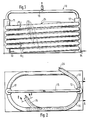
- the cooling device designated in its entirety by 10, has two insulated cooling gas containers 11, 12, which are preferably designed as standpipes and fastened on a base plate and to whose connections 13 and 14 a cooling gas supply (not shown in more detail) is connected, for supplying a low-boiling liquefied cooling gas , preferably liquid nitrogen.
- the liquid nitrogen is supplied evenly by level measurement.
- the standpipes 11, 12 are connected via a common pipe 15, via which the gaseous nitrogen which is formed can be removed in a manner known per se.
- the standpipes 11, 12 also serve as a holder for the vacuum-insulated cooling line segments 16, which are arranged parallel to each other and increasing at an angle ⁇ 1 of preferably 3 to 30 ° according to FIG. 1. This advantageously ensures that the outgassing nitrogen is transported by the buoyancy into the standpipes 11, 12. It has been found to be particularly advantageous if the angle ⁇ 1 from the cooling line segment to the cooling line segment becomes larger, for. B. from an angle ⁇ 1 of 1 ° continuously increases to a waving ⁇ 2 of 10 °.
- the vacuum-insulated cooling line segments 16 have an inner 17 and an outer 18 corrugated tube hose, the ends 19 of the corrugated tube hoses being connected / closed in a vacuum-insulated manner.
- a plastic spiral 20 is arranged as a spacer.
- the outer corrugated tube hose 18 is surrounded by a stainless steel braid 21.
- the cooling line segments 16 at openings in the standpipes 11, 12 z. B. connected by welds 23.
- the liquid gas line 24 to be cooled is routed continuously (preferably in a spiral) through the cooling segments and the cooling gas containers 11, 12, wherein, according to FIG. 3, the liquid gas line 24 penetrates the cooling gas containers 11, 12 and within the containers 11, 12 is not interrupted.
- the liquid gas line 24, which is preferably in the form of a high-pressure copper line, is held by plastic star-shaped spacers 25 and is precisely centered there, so that a between the liquid gas line 24 and the inner corrugated hose 17 Annulus for the cooling nitrogen is available.
- the arrangement described above offers the advantage of being able to lay long liquid gas pipes to be cooled without having to forego the space inside the pipe spiral. Furthermore, the weight is reduced since the nitrogen content in this embodiment is only along the liquid gas line to be cooled.
- the cooling device described can thus be used particularly advantageously in a device for cutting workpieces with liquid oxygen which is cooled with liquid nitrogen, the cooling device preferably being arranged on the cutting machine and being movable with it.
Landscapes
- Engineering & Computer Science (AREA)
- Mechanical Engineering (AREA)
- Physics & Mathematics (AREA)
- Chemical & Material Sciences (AREA)
- Combustion & Propulsion (AREA)
- Thermal Sciences (AREA)
- General Engineering & Computer Science (AREA)
- Life Sciences & Earth Sciences (AREA)
- Forests & Forestry (AREA)
- Optics & Photonics (AREA)
- Separation By Low-Temperature Treatments (AREA)
Applications Claiming Priority (2)
| Application Number | Priority Date | Filing Date | Title |
|---|---|---|---|
| DE3809290 | 1988-03-19 | ||
| DE3809290A DE3809290A1 (de) | 1988-03-19 | 1988-03-19 | Kuehleinrichtung |
Publications (2)
| Publication Number | Publication Date |
|---|---|
| EP0334037A2 true EP0334037A2 (fr) | 1989-09-27 |
| EP0334037A3 EP0334037A3 (fr) | 1990-11-28 |
Family
ID=6350182
Family Applications (1)
| Application Number | Title | Priority Date | Filing Date |
|---|---|---|---|
| EP19890103035 Withdrawn EP0334037A3 (fr) | 1988-03-19 | 1989-02-22 | Système de refroidissement |
Country Status (6)
| Country | Link |
|---|---|
| US (1) | US4953358A (fr) |
| EP (1) | EP0334037A3 (fr) |
| JP (1) | JPH01305280A (fr) |
| KR (1) | KR890014979A (fr) |
| CN (1) | CN1037579A (fr) |
| DE (1) | DE3809290A1 (fr) |
Cited By (1)
| Publication number | Priority date | Publication date | Assignee | Title |
|---|---|---|---|---|
| EP0624655A1 (fr) * | 1993-05-08 | 1994-11-17 | Messer Griesheim Gmbh | Procédé et dispositif pour le traitement de metal fondu, notamment d'acier avec une agent d'affinage |
Families Citing this family (6)
| Publication number | Priority date | Publication date | Assignee | Title |
|---|---|---|---|---|
| US6164078A (en) * | 1999-03-04 | 2000-12-26 | Boeing North American Inc. | Cryogenic liquid heat exchanger system with fluid ejector |
| DE10103447A1 (de) * | 2001-01-25 | 2002-08-01 | Baumueller Nuernberg Gmbh | Wellschlauch-Ständerkühlung in einer elektrischen Maschine |
| US6699036B2 (en) | 2002-05-06 | 2004-03-02 | Weber-Stephen Products Company | Curvilinear burner tube |
| US6945774B2 (en) * | 2003-03-07 | 2005-09-20 | Weber-Stephen Products Co. | Gas burner with flame stabilization structure |
| US20100024440A1 (en) * | 2008-08-04 | 2010-02-04 | John Dain | Flow Control of a Cryogenic Element to Remove Heat |
| CN111922519A (zh) * | 2020-08-10 | 2020-11-13 | 西安建筑科技大学 | 一种激光焊接装置 |
Family Cites Families (12)
| Publication number | Priority date | Publication date | Assignee | Title |
|---|---|---|---|---|
| US2205499A (en) * | 1937-04-27 | 1940-06-25 | Linde Air Prod Co | Method of cutting metals |
| US2858677A (en) * | 1955-04-11 | 1958-11-04 | Marley Co | Water cooling apparatus |
| US3433028A (en) * | 1966-09-02 | 1969-03-18 | Air Prod & Chem | Cryogenic fluid conveying system |
| DE1300380B (de) * | 1966-09-08 | 1969-07-31 | Kernforschungsanlage Juelich | Rohrleitungssystem fuer tiefkalte und/oder verfluessigte Gase mit einem evakuierten Mantelrohr |
| US3706208A (en) * | 1971-01-13 | 1972-12-19 | Air Prod & Chem | Flexible cryogenic liquid transfer system and improved support means therefor |
| US4036617A (en) * | 1975-04-18 | 1977-07-19 | Cryogenic Technology, Inc. | Support system for an elongated cryogenic envelope |
| US4210199A (en) * | 1978-06-14 | 1980-07-01 | Doucette Industries, Inc. | Heat exchange system |
| DE3036935A1 (de) * | 1980-09-30 | 1982-05-13 | Klaus Esser Gmbh & Co Kg, 4040 Neuss | Waermetauscher fuer ein waermetraegermedium |
| US4576015A (en) * | 1983-04-14 | 1986-03-18 | Crawford A Gerrit | Lightweight high pressure tubular storage system for compressed gas and method for cryogenic pressurization |
| DE3543657C3 (de) * | 1985-12-11 | 1993-12-02 | Messer Griesheim Gmbh | Verfahren und Vorrichtung zum autogenen Brennschneiden von Sauerstoff |
| US4715187A (en) * | 1986-09-29 | 1987-12-29 | Vacuum Barrier Corporation | Controlled cryogenic liquid delivery |
| US4745760A (en) * | 1987-07-21 | 1988-05-24 | Ncr Corporation | Cryogenic fluid transfer conduit |
-
1988
- 1988-03-19 DE DE3809290A patent/DE3809290A1/de not_active Withdrawn
-
1989
- 1989-02-22 EP EP19890103035 patent/EP0334037A3/fr not_active Withdrawn
- 1989-03-13 US US07/322,194 patent/US4953358A/en not_active Expired - Fee Related
- 1989-03-16 KR KR1019890003244A patent/KR890014979A/ko not_active Withdrawn
- 1989-03-18 CN CN89101524A patent/CN1037579A/zh active Pending
- 1989-03-20 JP JP1066494A patent/JPH01305280A/ja active Pending
Cited By (1)
| Publication number | Priority date | Publication date | Assignee | Title |
|---|---|---|---|---|
| EP0624655A1 (fr) * | 1993-05-08 | 1994-11-17 | Messer Griesheim Gmbh | Procédé et dispositif pour le traitement de metal fondu, notamment d'acier avec une agent d'affinage |
Also Published As
| Publication number | Publication date |
|---|---|
| JPH01305280A (ja) | 1989-12-08 |
| EP0334037A3 (fr) | 1990-11-28 |
| DE3809290A1 (de) | 1989-10-05 |
| CN1037579A (zh) | 1989-11-29 |
| KR890014979A (ko) | 1989-10-25 |
| US4953358A (en) | 1990-09-04 |
Similar Documents
| Publication | Publication Date | Title |
|---|---|---|
| DE7927533U1 (de) | Transportleitung fuer tiefkalte und/oder verfluessigte gase | |
| EP2959208B1 (fr) | Réservoir sous pression muni d'un échangeur de chaleur pour un fluide stocké sous forme cryogénique | |
| EP0334037A2 (fr) | Système de refroidissement | |
| EP1064493B1 (fr) | Dispositif de stockage de gaz sous pression | |
| DE19837886C2 (de) | Speicherbehälter für kryogene Flüssigkeiten | |
| DE69007942T2 (de) | Gefäss für kryogene Flüssigkeit. | |
| DE2821010A1 (de) | Tank fuer fluessiggas und verfahren zu dessen fuellen | |
| EP0334036B2 (fr) | Torche de découpage à jet liquide | |
| DE1227575B (de) | Regelstabvorrichtung fuer einen Kernreaktor | |
| DE4041170C1 (en) | Double-walled insulated container - incorporates metal woven band with shield made of aluminium | |
| EP3210890B1 (fr) | Refroidissement de carburant pour un moteur | |
| DE102020117910B4 (de) | Druckgastank für ein Kraftfahrzeug | |
| DE2136732A1 (de) | Vorrichtung zum speichern eines gases in einem loesungsmittel | |
| DE2818520A1 (de) | Druckbehaelter | |
| EP1015828A1 (fr) | Installation pour la decomposition a basse temperature de l'air | |
| DE2054054A1 (en) | Cryostat coolant supply - with facility for switching from evaporative to gas cooling | |
| DE1514976A1 (de) | Kernreaktor | |
| DE2420888C3 (de) | Säulenartige Schleifringanordnung für den Wähler und Anzapfumsteller von Stufenschaltern für Transformatoren | |
| DE1910405A1 (de) | Verfahren und Einrichtung zum Herstellen von aus mindestens drei Komponenten bestehenden Schutzgasgemischen fuer das Schweissen und Schneiden | |
| DE3431161A1 (de) | Kuehlvorrichtung | |
| DE19700259B4 (de) | Pistole zum Erzeugen von Montageschaum | |
| DE1551392A1 (de) | Fluessiggas-Kuehlanlage,insbesondere Stickstoff-Kuehlanlage fuer Kuehlfahrzeuge und Kuehlbehaelter | |
| DE1204694B (de) | Vorrichtung zum Umfuellen tiefsiedender verfluessigter Gase mit einem ein Absperrventil enthaltenden Vakuummantelheber | |
| DE2419601C2 (de) | Rohrförmige Hochdruckleitung zur Verbindung zweier Behälter | |
| DE624890C (de) | Schalter, dessen Lichtbogen mit Hilfe von Fluessigkeit in einer Loeschvorrichtung geloescht wird |
Legal Events
| Date | Code | Title | Description |
|---|---|---|---|
| PUAI | Public reference made under article 153(3) epc to a published international application that has entered the european phase |
Free format text: ORIGINAL CODE: 0009012 |
|
| AK | Designated contracting states |
Kind code of ref document: A2 Designated state(s): AT BE DE ES FR GB IT LU |
|
| PUAL | Search report despatched |
Free format text: ORIGINAL CODE: 0009013 |
|
| AK | Designated contracting states |
Kind code of ref document: A3 Designated state(s): AT BE DE ES FR GB IT LU |
|
| RHK1 | Main classification (correction) |
Ipc: F25D 3/10 |
|
| 17P | Request for examination filed |
Effective date: 19901018 |
|
| 17Q | First examination report despatched |
Effective date: 19911015 |
|
| STAA | Information on the status of an ep patent application or granted ep patent |
Free format text: STATUS: THE APPLICATION IS DEEMED TO BE WITHDRAWN |
|
| 18D | Application deemed to be withdrawn |
Effective date: 19920929 |