EP0334008A2 - Interrupteur mono-pression à SF6 - Google Patents
Interrupteur mono-pression à SF6 Download PDFInfo
- Publication number
- EP0334008A2 EP0334008A2 EP89102110A EP89102110A EP0334008A2 EP 0334008 A2 EP0334008 A2 EP 0334008A2 EP 89102110 A EP89102110 A EP 89102110A EP 89102110 A EP89102110 A EP 89102110A EP 0334008 A2 EP0334008 A2 EP 0334008A2
- Authority
- EP
- European Patent Office
- Prior art keywords
- opening
- closure member
- switching
- switch according
- gas
- Prior art date
- Legal status (The legal status is an assumption and is not a legal conclusion. Google has not performed a legal analysis and makes no representation as to the accuracy of the status listed.)
- Granted
Links
- 238000007906 compression Methods 0.000 claims abstract description 63
- 230000006835 compression Effects 0.000 claims abstract description 60
- 238000009423 ventilation Methods 0.000 claims description 10
- 238000010791 quenching Methods 0.000 claims description 9
- 230000000171 quenching effect Effects 0.000 claims description 9
- 239000011810 insulating material Substances 0.000 claims description 5
- 238000013022 venting Methods 0.000 claims description 4
- 230000008859 change Effects 0.000 claims description 3
- 238000006073 displacement reaction Methods 0.000 claims 1
- 238000007664 blowing Methods 0.000 abstract description 16
- 238000006243 chemical reaction Methods 0.000 abstract description 3
- 230000000694 effects Effects 0.000 abstract description 2
- 230000008901 benefit Effects 0.000 description 9
- 238000005192 partition Methods 0.000 description 5
- 230000015572 biosynthetic process Effects 0.000 description 4
- 238000013461 design Methods 0.000 description 4
- 238000013459 approach Methods 0.000 description 2
- 238000010438 heat treatment Methods 0.000 description 2
- 230000001404 mediated effect Effects 0.000 description 2
- 238000000034 method Methods 0.000 description 2
- 230000035515 penetration Effects 0.000 description 2
- 230000008569 process Effects 0.000 description 2
- 238000003786 synthesis reaction Methods 0.000 description 2
- 230000007423 decrease Effects 0.000 description 1
- 230000003111 delayed effect Effects 0.000 description 1
- 238000011161 development Methods 0.000 description 1
- 230000018109 developmental process Effects 0.000 description 1
- 230000001771 impaired effect Effects 0.000 description 1
- 238000007373 indentation Methods 0.000 description 1
- 239000012212 insulator Substances 0.000 description 1
- 239000000463 material Substances 0.000 description 1
- 239000002184 metal Substances 0.000 description 1
- 239000000203 mixture Substances 0.000 description 1
- 210000000056 organ Anatomy 0.000 description 1
- 229910052573 porcelain Inorganic materials 0.000 description 1
- 230000009467 reduction Effects 0.000 description 1
- 230000000717 retained effect Effects 0.000 description 1
- 238000007789 sealing Methods 0.000 description 1
- 238000013517 stratification Methods 0.000 description 1
- 230000007704 transition Effects 0.000 description 1
Images

Classifications
-
- H—ELECTRICITY
- H01—ELECTRIC ELEMENTS
- H01H—ELECTRIC SWITCHES; RELAYS; SELECTORS; EMERGENCY PROTECTIVE DEVICES
- H01H33/00—High-tension or heavy-current switches with arc-extinguishing or arc-preventing means
- H01H33/70—Switches with separate means for directing, obtaining, or increasing flow of arc-extinguishing fluid
- H01H33/88—Switches with separate means for directing, obtaining, or increasing flow of arc-extinguishing fluid the flow of arc-extinguishing fluid being produced or increased by movement of pistons or other pressure-producing parts
- H01H33/90—Switches with separate means for directing, obtaining, or increasing flow of arc-extinguishing fluid the flow of arc-extinguishing fluid being produced or increased by movement of pistons or other pressure-producing parts this movement being effected by or in conjunction with the contact-operating mechanism
- H01H33/901—Switches with separate means for directing, obtaining, or increasing flow of arc-extinguishing fluid the flow of arc-extinguishing fluid being produced or increased by movement of pistons or other pressure-producing parts this movement being effected by or in conjunction with the contact-operating mechanism making use of the energy of the arc or an auxiliary arc
-
- H—ELECTRICITY
- H01—ELECTRIC ELEMENTS
- H01H—ELECTRIC SWITCHES; RELAYS; SELECTORS; EMERGENCY PROTECTIVE DEVICES
- H01H33/00—High-tension or heavy-current switches with arc-extinguishing or arc-preventing means
- H01H33/70—Switches with separate means for directing, obtaining, or increasing flow of arc-extinguishing fluid
- H01H33/88—Switches with separate means for directing, obtaining, or increasing flow of arc-extinguishing fluid the flow of arc-extinguishing fluid being produced or increased by movement of pistons or other pressure-producing parts
- H01H33/90—Switches with separate means for directing, obtaining, or increasing flow of arc-extinguishing fluid the flow of arc-extinguishing fluid being produced or increased by movement of pistons or other pressure-producing parts this movement being effected by or in conjunction with the contact-operating mechanism
- H01H2033/906—Switches with separate means for directing, obtaining, or increasing flow of arc-extinguishing fluid the flow of arc-extinguishing fluid being produced or increased by movement of pistons or other pressure-producing parts this movement being effected by or in conjunction with the contact-operating mechanism with pressure limitation in the compression volume, e.g. by valves or bleeder openings
-
- H—ELECTRICITY
- H01—ELECTRIC ELEMENTS
- H01H—ELECTRIC SWITCHES; RELAYS; SELECTORS; EMERGENCY PROTECTIVE DEVICES
- H01H33/00—High-tension or heavy-current switches with arc-extinguishing or arc-preventing means
- H01H33/70—Switches with separate means for directing, obtaining, or increasing flow of arc-extinguishing fluid
- H01H33/88—Switches with separate means for directing, obtaining, or increasing flow of arc-extinguishing fluid the flow of arc-extinguishing fluid being produced or increased by movement of pistons or other pressure-producing parts
- H01H33/90—Switches with separate means for directing, obtaining, or increasing flow of arc-extinguishing fluid the flow of arc-extinguishing fluid being produced or increased by movement of pistons or other pressure-producing parts this movement being effected by or in conjunction with the contact-operating mechanism
- H01H2033/908—Switches with separate means for directing, obtaining, or increasing flow of arc-extinguishing fluid the flow of arc-extinguishing fluid being produced or increased by movement of pistons or other pressure-producing parts this movement being effected by or in conjunction with the contact-operating mechanism using valves for regulating communication between, e.g. arc space, hot volume, compression volume, surrounding volume
Definitions
- the invention relates to an SF6 impression switch with a switching chamber filled with insulating gas, at least two switching pieces, at least one of which is movable by a drive rod, a compression device for the insulating gas which can be actuated by this switching movement and whose compression space is delimited by two opposite, relatively movable floors.
- High-voltage switches are usually designed as auto-blow switches filled with insulating gas.
- the contacts are separated and the arc is blown with the insulating gas, usually SF6, until it goes out.
- the compression required for this blowing is achieved either by means of a compression device or by means of the thermal energy of the arc itself.
- the interrupters are either surrounded by a fully insulated metal housing or by a porcelain insulator.
- an SF6 impression switch which has a switching chamber filled with insulating gas, in which there are two contact pieces, one of which is stationary and the other is displaceable with the switching movement.
- the switching movement actuates a compression device, which consists of a compression piston and a compression cylinder with a cylinder base stands. Passages in this cylinder base connect the compression chamber with a pressure chamber, which is surrounded by an insulating material nozzle.
- Arcs the current strength of which are in the lower and middle range, are extinguished by the compression device compressing extinguishing gas and blowing it through the passages in the cylinder bottom into the pressure chamber, as a result of which a strong flow of extinguishing gas arises in the nozzle, which extinguishes the arc at zero current.
- the known SF6 indentation switch has disadvantages in three ways in switching operations with high-current arcs: - The switching process is braked. - Part of the expanding extinguishing gas is lost for the blowing. - The strong mixture of cold extinguishing gas with hot extinguishing gas reduces the extinguishing properties.
- the invention is therefore based on the object to make an SF6 impression switch available, which additionally uses the arc energy for arc extinguishing in the case of high-current arcs, ensures blowing with cold insulating gas of high density and prevents the arc energy from reacting to the drive.
- a pressure chamber is arranged between the insulating nozzle and the bottom facing it, which has an outflow opening that can be closed by a non-return valve in the direction of the switching path, that an inflow opening that can be closed by means of a closure member is arranged in the bottom, that a with the Switching path connected gas storage space extends to an opening which can be closed by means of the closure member, which opens into the part of the pressure chamber which faces away from the outflow opening, that in a first position of the closure member the inflow opening is opened and the opening is closed, and that in a second position of the closure member the inflow opening is closed and the opening is open, the change in position of the closure member being controllable by the switching path covered or by the pressures occurring.
- the invention is a synthesis of the SF6 impression switch proposed by P 37 20 816 with the auto-blow switch with gas storage space proposed by P 37 32 137.
- the SF6 impression switch according to the invention has the advantage, above all, of carrying out blowing in the case of weaker electric arcs, as is done in a conventional and expedient manner in conventional SF6 impression switches, but to adjust fully to the significantly increased requirements in the case of high-current arcs.
- the gas is pre-compressed by a compression device, which creates a gas cushion of cold, high-density quenching gas.
- This gas cushion is post-compressed by the gas pressure wave, which causes the gas expansion of the high-current arc.
- This post-compression takes place in such a way that the hot gas is first cooled in the gas storage space and then flows into the pressure chamber in such a way that a stratification is formed in it, in which the pre-compressed, high-density gas cushion is first available for blowing.
- the cooled gas forms a layer in the lower part of the pressure chamber, since it only flows in after the cold gas has been compressed. It primarily serves to increase the pressure and is only used for post-blowing after the arc has been extinguished in order to avoid reignition.
- the blowing begins as soon as a sufficient distance between the switch contacts to extinguish the arc is reached.
- the invention has the further advantage that there is no further reduction in the switching speed due to the penetration of gas into the compression space as a result of the gas expansion by means of high-current arcs. As a result of the post-compression in the pressure chamber by means of the expanding gas, this energy is still available for blowing the high-current arcs and does not have a braking effect on the drive. This leads to a safe extinguishing of the arc by a higher switching speed and better blowing with a gas that has an optimal density.
- Fig. 1 shows an embodiment, the SF6 impression switch is shown in a partial view, in which the essential parts are shown by means of a section extending to the axis of rotation.
- This exemplary embodiment contains the parts that are customary in an SF6 impression switch: 2 switching pieces 20 and 21, which form a switching path 4 when the switch is opened. Of these contact pieces, one contact piece 20 is fixed and the other contact piece 21 is driven by a drive rod 19 from the switch-on to the switch-off position (and vice versa). bringable.
- the arc 23 which arises in the switching path 4 when it is switched off is blown by means of a compression device. In this case, an insulating gas stream is directed by means of an insulating material nozzle 12 onto the arc 23 burning in the switching path 4.
- This compression device consists, as is usual with SF6 impression switches, of a compression cylinder 17 and two floors 1 and 2, which move towards one another when switched off and thus compress the insulating gas in a compression space 11.
- the compression cylinder 17 is connected as a fixed part to the base 2 and the base 1, which is connected to the switching piece 21 and the drive rod 19, is drawn into the compression cylinder 17.
- a pressure chamber 3 is located between the base 1 and the insulating material nozzle 12 and a gas storage space 9 is separated therefrom by a partition 25.
- the pressure chamber 3 is provided in the direction of the switching path 4 with an outflow opening 5, in which an insulating gas heated by the arc flows in a check valve 6 is prevented.
- the gas storage space 9 has an inlet 26 in the direction of the switching path 4 and an opening 10 which opens into the pressure chamber 3 on the side opposite the outflow opening 5.
- the bottom 1 is provided with an inflow opening 7, which connects the compression space 11 to the pressure chamber 3.
- a closure element 8 is arranged in the region of the opening 10 and the inflow opening 7.
- This closure member 8 in Fig. 1 is designed as a slidable ring with an L-shaped cross section. It can assume two positions: a first position in which the axial leg of the closure element 8 is pushed in a sealing manner in front of the opening 10 and opens the inflow opening 7. In a second position, in which the closure member 8 is located in the illustration in FIG. 1, the opening 10 is opened and the inflow opening 7 is closed by the radial leg of the closure member 8. If no pressure differences act on the closure member 8, it is held by a spring 24 in this second position shown.
- the bottom 2 is designed as a fixed component, the drive rod 19 passing through a hole in this bottom and a seal for the gas tightness of this passage worries.
- a vent hole 13 is arranged, which is provided with a vent valve 14, which opens against the pressure of a spring 14 '. Furthermore, the bottom 2 contains a ventilation hole 15 with a valve 16, which is arranged so that the compression chamber 11 is ventilated when it is switched on.
- the SF6 impression switch shown has the following functions: When switching off low currents, the function corresponds to that known from conventional SF6 impression switches: The gas is compressed by the switching movement, mediated by the drive rod 19, between the base 1 connected to the drive rod 19 and the fixed base 2 in the compression space 11, passes through the inflow opening 7 and flows through the opening 5 to the arc 23 around it to blow at zero crossing.
- the quenching gas opens the closure element 8 in this way, flows through the pressure chamber 3 and, after leaving the pressure chamber 3 through the outflow opening 5, finally reaches the switching path 4 in order to blow the arc 23.
- the outflow opening 5 is not closed by the check valve 6, since in the case of low-current arcs there is no gas pressure wave so strong that a gas flow is formed which flows from the switching path in the direction of the compression device.
- the SF6 impression switch adapts to the conditions caused by the gas expansion and uses this gas expansion to produce the required insulating gas pressure:
- insulating gas is compressed in the compression space 11 in the manner described above, flows through the inflow opening 7 into the pressure chamber 3, the closure member 8 being opened by the gas flow.
- the arc 23 is drawn in the switching path 4, as a result of which extinguishing gas expands and, as represented by the curved arrow, flows in the direction of the compression device.
- the outflow opening 5 is closed by the check valve 6 and the pressurized gas flows into the gas storage space 9.
- the closed check valve 6 in the pressure chamber 3 and the compression chamber 11 produce reproducible pressure conditions, so that a certain pressure can be assigned to a certain distance between the switching contacts 21 and 22.
- the pressure in the compression space 11 drops sharply, which has the consequence that the closure member 8 moves into the position in which it closes the inflow opening 7 with its radial leg and at the same time opens the opening 10.
- the drive is completely relieved of the pressure force in the compression space 11 by venting it, so that there is no braking of the switching movement or even a backward movement, on the contrary - the switching movement is even accelerated by the relief.
- the drive advantageously only has to apply the energy for the pre-compression of the gas in the pressure chamber 3.
- the expanded gas which is stored in the gas storage space 9 and thereby cooled, flows through the opening 10 into the pressure chamber 3.
- the cold gas pre-compressed in the pressure chamber 3 is post-compressed by the gas pressure wave coming from the gas storage space 9, which cold gas of high density lies in front of the outflow opening 5 in order to serve the blowing at the moment of zero current crossing which is decisive for the extinguishing of the arc.
- the gas pressure generated by the arc 23 decreases, the check valve 6 opens and the cold gas cushion flows out of the outflow opening 5 in the direction of the switching path 4 in order to blow the arc there. In this way, optimal extinguishing conditions were created while the drive was relieved.
- Fig. 2 shows an embodiment in which the compression cylinder 17 is fixedly connected to the floor 1 and is pulled by the switching movement mediated by the drive rod 19 over the fixed floor 2.
- the vent valve 14 is opened against the force of a spring 14 ⁇ by a pin 18.
- the length of this pin 18 is dimensioned such that the vent valve 14 lifts the valve plate of the vent valve 14 out of its closed position when a sufficient distance between the switching contacts 20 and 21 is reached for arc quenching.
- the spring 14 ⁇ must have a larger spring constant than the spring 14 'described in Fig. 1'.
- the closure member 8 is also designed as an L-shaped ring, but the axial leg is longer and the opening 10 in the second position exposes through holes. The remaining parts correspond in structure and function to those already described for FIG. 1.
- Fig. 2 serves to make it clear that different configurations of the floors 1 and 2 and the cylinder 17 and the control of the closure member 8 are possible. However, further different configurations are conceivable, for example an embodiment in which the drive rod is connected to the base 2 and the switching piece 20 and the other parts are fixed.
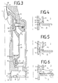
- FIG. 3 A third embodiment is shown in FIG. 3. This has an L-shaped closure member 8, which is held by an embedded spring 24 'in the first position as the rest position.
- the spring constant of this spring 24 ' is designed so that when the compression chamber 11 is vented, the pressure in the pressure chamber 3 presses the closure member 8 into the second position in which the inflow opening 7 is closed and the opening 10 is opened at the same time.
- the ventilation of the compression space 11 is brought about by the fact that the floor 2 runs in the course of its switching-on movement over a recess 22 arranged on the compression cylinder 17 and / or on the drive rod 19. This recess 22 must be arranged so that the ventilation takes place when the switch contacts 20, 21 are at a sufficient distance to achieve an arc extinguishing.
- 3 shows the position at which the ventilation of the compression space 11 begins.
- the bottom 2 in FIG. 3 is provided with a ventilation hole 15, which is closed by a check valve 16 during the switch-off movement.
- Check valve 16 and ventilation hole 15 serve to vent the compression chamber 11 during the switch-on movement.
- the ventilation hole 15 with the check valve 16 at another point, for. B. be arranged on the compression cylinder 17 so that the bore 15 opens into a part of the compression space 11, which is still retained in the off position.
- a check valve 27 is provided in the area of the opening 10 of the gas storage space 9, which prevents insulating gas from flowing back through the opening 10 into the gas storage space 9. This check valve is used when switching small currents to prevent a pressure loss of the pressure chamber 3 through the opening 10 into the gas storage space 9 during the second phase of the switch-off movement.
- the check valve 6 of the outflow opening 5 has an additional valve plate 6 ', which closes the cross section of the inlet 26 between the switching path 4 and the gas storage space 9 when the check valve 6 is open.
- This valve plate 6 ' ensures that the hot gas which has entered the gas storage space 9 as a result of strong gas expansion when the current approaches zero crossing and the resulting opening of the check valve 6 cannot flow back in the direction of the switching path 4, which causes mixing with the cold gas would result from the pressure chamber 3 and thereby deteriorate the extinguishing properties of this gas.
- Fig. 4 shows the closure member 8 'formed as at least one flap that closes the opening 10 in the first position and opens the inflow opening 7 to the pressure chamber 3 and the inflow in the second position Closes opening 7 and opens opening 10 to pressure chamber 3.
- the flap-shaped closure member 8 ' can be arranged, for example, with its fulcrum in the region of the drive rod 9, so that it rests in a horizontal position on the floor 1 and closes the opening 7 and at the same time opens the opening 10 to the pressure chamber 3.
- Fig. 5 shows the formation of the closure member 8 ⁇ as a sliding ring.
- This displaceable ring has a sliding surface on the inside to the drive rod 19, which is gas-tight.
- the closure member 8 ⁇ is drawn in its second position, in which it rests with its outer end on the floor 1 and thereby closes the inflow opening 7.
- the closure member 8 ⁇ is moved upward and abuts with its outer end on the partition wall 25, whereby the inflow opening 7 is connected to the pressure chamber 3 and closes the opening 10.
- the closure member 8 ⁇ is also designed as a displaceable ring, with the difference that the displaceable ring has a more plate-like shape and the inflow opening 7 can be arranged further out as seen from the axis of symmetry.
- the closure member 8 ⁇ is also in one position on the floor 1, closes the opening 7 and strikes in its other position on the partition 25, whereby the opening 10 is closed, the other opening being opened.
- closure members 8 'and 8 ⁇ are controlled by the pressures. Both during the first phase of the switch-off movement with high-current arcs and during the entire switch-off movement with low-current arcs, the strongest pressure P 3 occurs in the compression space 11. Characterized the closure members 8 ', 8, are pressed into their first position, in which they strike the partition 25 and thereby close the opening 10.
- the gas can flow from the compression space 11 into the pressure chamber 3.
- the expanding gas flows into the gas storage space 9 and from there to the opening 10.
- the pressure P2 thereby becomes higher than the pressures P1 and P3, so that the closure member 8 'or 8 ⁇ is pressed into its second position in which it rests on the bottom 1 and thereby closes the inflow opening 7 and opens the opening 10 to the pressure chamber 3.
- the pressure wave can flow into the pressure chamber 3 for post-compression.
- closure member 8 'or 8' is controlled by the gas pressure wave itself, which means that the transition from the first phase of the opening movement into the second phase of the opening movement is controlled by the gas pressure wave according to the arc formed in each case .
- a spring can be arranged which the closure member 8 ', 8 ⁇ holds in their first or second position. Presses z. B. a spring the closure member 8 ', 8 ⁇ against the bottom 1, the closure member 8', 8 ⁇ is already adjusted when the pressure P2 has almost reached the pressure P3. An inverted spring causes an adjustment of the closure member 8 ', 8 ⁇ takes place only when the pressure P2 is above the pressure P3 according to the spring strength.
- Another advantage of the design of the closure member according to Fig. 4 to Fig. 6 is that when switching low-current arcs, penetration of gas into the gas storage space 9 is prevented through the opening 10, since the closure member 8 ', 8' in its first Position remains.
- an embodiment of the closure member as shown in FIGS. 4 to 6, can be connected to one of the aforementioned vents of the compression space 11, this ventilation being controlled in such a way that the compression space 11 is vented when the switching movement is so advanced that further compression of the gas can no longer benefit the arc quenching.
- a faster switching movement is achieved in the final phase of the switch-off even if the current strength is too low for the formation of a gas pressure wave, as a result of which additional security against re-ignition of the arc is achieved even with such currents.
Landscapes
- Circuit Breakers (AREA)
Applications Claiming Priority (2)
| Application Number | Priority Date | Filing Date | Title |
|---|---|---|---|
| DE3810091 | 1988-03-25 | ||
| DE3810091A DE3810091A1 (de) | 1988-03-25 | 1988-03-25 | Sf(pfeil abwaerts)6(pfeil abwaerts)-eindruckschalter |
Publications (3)
| Publication Number | Publication Date |
|---|---|
| EP0334008A2 true EP0334008A2 (fr) | 1989-09-27 |
| EP0334008A3 EP0334008A3 (fr) | 1991-01-23 |
| EP0334008B1 EP0334008B1 (fr) | 1992-04-22 |
Family
ID=6350663
Family Applications (1)
| Application Number | Title | Priority Date | Filing Date |
|---|---|---|---|
| EP89102110A Expired - Lifetime EP0334008B1 (fr) | 1988-03-25 | 1989-02-08 | Interrupteur mono-pression à SF6 |
Country Status (2)
| Country | Link |
|---|---|
| EP (1) | EP0334008B1 (fr) |
| DE (2) | DE3810091A1 (fr) |
Cited By (2)
| Publication number | Priority date | Publication date | Assignee | Title |
|---|---|---|---|---|
| EP1372172A1 (fr) * | 2002-06-12 | 2003-12-17 | Alstom | Disjoncteur à gaz comprimé |
| CN102306590A (zh) * | 2011-06-01 | 2012-01-04 | 厦门华电开关有限公司 | 断路器灭弧室 |
Families Citing this family (3)
| Publication number | Priority date | Publication date | Assignee | Title |
|---|---|---|---|---|
| DE3942489C2 (de) * | 1989-12-22 | 1994-03-10 | Licentia Gmbh | Druckgasschalter |
| FR2704976B1 (fr) * | 1993-05-07 | 1995-06-23 | Gec Alsthom T & D Sa | Disjoncteur a gaz de soufflage a haute ou moyenne tension. |
| DE19547522C1 (de) * | 1995-12-08 | 1997-01-16 | Siemens Ag | Hochspannungs-Leistungsschalter mit einem Gasspeicherraum |
Family Cites Families (4)
| Publication number | Priority date | Publication date | Assignee | Title |
|---|---|---|---|---|
| CH568649A5 (fr) * | 1974-07-29 | 1975-10-31 | Sprecher & Schuh Ag | |
| FR2563372B1 (fr) * | 1984-04-24 | 1988-02-26 | Alsthom Atlantique | Disjoncteur haute tension a soufflage d'arc |
| DE3438635A1 (de) * | 1984-09-26 | 1986-04-03 | BBC Aktiengesellschaft Brown, Boveri & Cie., Baden, Aargau | Druckgasschalter |
| FR2596575B1 (fr) * | 1986-03-26 | 1988-05-20 | Alsthom | Disjoncteur a gaz dielectrique sous pression |
-
1988
- 1988-03-25 DE DE3810091A patent/DE3810091A1/de not_active Withdrawn
-
1989
- 1989-02-08 EP EP89102110A patent/EP0334008B1/fr not_active Expired - Lifetime
- 1989-02-08 DE DE8989102110T patent/DE58901215D1/de not_active Expired - Fee Related
Cited By (4)
| Publication number | Priority date | Publication date | Assignee | Title |
|---|---|---|---|---|
| EP1372172A1 (fr) * | 2002-06-12 | 2003-12-17 | Alstom | Disjoncteur à gaz comprimé |
| CN102306590A (zh) * | 2011-06-01 | 2012-01-04 | 厦门华电开关有限公司 | 断路器灭弧室 |
| WO2012163068A1 (fr) * | 2011-06-01 | 2012-12-06 | 厦门华电开关有限公司 | Chambre à extinction d'arc d'un disjoncteur |
| CN102306590B (zh) * | 2011-06-01 | 2013-08-28 | 厦门华电开关有限公司 | 断路器灭弧室 |
Also Published As
| Publication number | Publication date |
|---|---|
| EP0334008A3 (fr) | 1991-01-23 |
| EP0334008B1 (fr) | 1992-04-22 |
| DE58901215D1 (de) | 1992-05-27 |
| DE3810091A1 (de) | 1989-10-05 |
Similar Documents
| Publication | Publication Date | Title |
|---|---|---|
| EP0067460B2 (fr) | Disjoncteur de puissance pour haute tension | |
| DE3247121C2 (fr) | ||
| EP0766278A2 (fr) | Disjoncteur | |
| DE69516206T2 (de) | Lastschalter mit reduzierter Kompression | |
| EP0296363B1 (fr) | Interrupteur à écoulement de gaz d'extinction autoengendré | |
| DE3915700C2 (fr) | ||
| DE3872090T2 (de) | Druckgasschalter fuer hoch- oder mittelspannung mit von der lichtbogenenergie entnommener ausschaltenergie. | |
| EP0334008B1 (fr) | Interrupteur mono-pression à SF6 | |
| EP0744759B1 (fr) | Disjoncteur pour haute tension avec chambre de réchauffement fixe | |
| DE4103119A1 (de) | Druckgasschalter | |
| EP0959483B1 (fr) | Sectionneur de coupure en charge avec une chambre d'extinction | |
| EP0025833B1 (fr) | Interrupteur à gaz comprimé | |
| DE3930548C2 (de) | Druckgasschalter | |
| DE69112568T2 (de) | Hochspannungslastschalter. | |
| DE4015179C2 (de) | Druckgasschalter | |
| DE69106436T2 (de) | Mittelspannungsschalter. | |
| EP0374384B1 (fr) | Interrupteur monopression à SF6 | |
| DE4025553C2 (de) | Druckgasschalter | |
| DE2635573A1 (de) | Druckgas-blas-leistungsschalter | |
| EP4024425B1 (fr) | Dispositif de commutation pourvu d'élément buse mobile | |
| EP0729637B1 (fr) | Disjoncteur electrique a gaz comprime | |
| DE19524637C2 (de) | Druckgasschalter | |
| AT398140B (de) | Druckgasschalter | |
| EP1225610B1 (fr) | Agencement de contacts d'arc pour disjoncteur | |
| DE3843406A1 (de) | Sf(pfeil abwaerts)6(pfeil abwaerts)-eindruckschalter |
Legal Events
| Date | Code | Title | Description |
|---|---|---|---|
| PUAI | Public reference made under article 153(3) epc to a published international application that has entered the european phase |
Free format text: ORIGINAL CODE: 0009012 |
|
| AK | Designated contracting states |
Kind code of ref document: A2 Designated state(s): CH DE FR IT LI SE |
|
| PUAL | Search report despatched |
Free format text: ORIGINAL CODE: 0009013 |
|
| AK | Designated contracting states |
Kind code of ref document: A3 Designated state(s): CH DE FR IT LI SE |
|
| 17P | Request for examination filed |
Effective date: 19910129 |
|
| 17Q | First examination report despatched |
Effective date: 19910722 |
|
| GRAA | (expected) grant |
Free format text: ORIGINAL CODE: 0009210 |
|
| AK | Designated contracting states |
Kind code of ref document: B1 Designated state(s): CH DE FR IT LI SE |
|
| REF | Corresponds to: |
Ref document number: 58901215 Country of ref document: DE Date of ref document: 19920527 |
|
| ET | Fr: translation filed | ||
| ITF | It: translation for a ep patent filed | ||
| PLBE | No opposition filed within time limit |
Free format text: ORIGINAL CODE: 0009261 |
|
| STAA | Information on the status of an ep patent application or granted ep patent |
Free format text: STATUS: NO OPPOSITION FILED WITHIN TIME LIMIT |
|
| 26N | No opposition filed | ||
| EAL | Se: european patent in force in sweden |
Ref document number: 89102110.7 |
|
| REG | Reference to a national code |
Ref country code: CH Ref legal event code: PUE Owner name: LICENTIA PATENT- VERWALTUNGS-GMBH TRANSFER- AEG EN |
|
| REG | Reference to a national code |
Ref country code: FR Ref legal event code: TP |
|
| PGFP | Annual fee paid to national office [announced via postgrant information from national office to epo] |
Ref country code: FR Payment date: 20000215 Year of fee payment: 12 |
|
| PGFP | Annual fee paid to national office [announced via postgrant information from national office to epo] |
Ref country code: SE Payment date: 20000218 Year of fee payment: 12 Ref country code: CH Payment date: 20000218 Year of fee payment: 12 |
|
| PGFP | Annual fee paid to national office [announced via postgrant information from national office to epo] |
Ref country code: DE Payment date: 20000426 Year of fee payment: 12 |
|
| PG25 | Lapsed in a contracting state [announced via postgrant information from national office to epo] |
Ref country code: SE Free format text: LAPSE BECAUSE OF NON-PAYMENT OF DUE FEES Effective date: 20010209 |
|
| PG25 | Lapsed in a contracting state [announced via postgrant information from national office to epo] |
Ref country code: LI Free format text: LAPSE BECAUSE OF NON-PAYMENT OF DUE FEES Effective date: 20010228 Ref country code: CH Free format text: LAPSE BECAUSE OF NON-PAYMENT OF DUE FEES Effective date: 20010228 |
|
| REG | Reference to a national code |
Ref country code: CH Ref legal event code: PL |
|
| EUG | Se: european patent has lapsed |
Ref document number: 89102110.7 |
|
| PG25 | Lapsed in a contracting state [announced via postgrant information from national office to epo] |
Ref country code: FR Free format text: LAPSE BECAUSE OF NON-PAYMENT OF DUE FEES Effective date: 20011031 |
|
| REG | Reference to a national code |
Ref country code: FR Ref legal event code: ST |
|
| PG25 | Lapsed in a contracting state [announced via postgrant information from national office to epo] |
Ref country code: DE Free format text: LAPSE BECAUSE OF NON-PAYMENT OF DUE FEES Effective date: 20011201 |
|
| PG25 | Lapsed in a contracting state [announced via postgrant information from national office to epo] |
Ref country code: IT Free format text: LAPSE BECAUSE OF NON-PAYMENT OF DUE FEES Effective date: 20050208 |