EP0334008A2 - Single-pressure switch with SF6 - Google Patents
Single-pressure switch with SF6 Download PDFInfo
- Publication number
- EP0334008A2 EP0334008A2 EP89102110A EP89102110A EP0334008A2 EP 0334008 A2 EP0334008 A2 EP 0334008A2 EP 89102110 A EP89102110 A EP 89102110A EP 89102110 A EP89102110 A EP 89102110A EP 0334008 A2 EP0334008 A2 EP 0334008A2
- Authority
- EP
- European Patent Office
- Prior art keywords
- opening
- closure member
- switch according
- gas
- opens
- Prior art date
- Legal status (The legal status is an assumption and is not a legal conclusion. Google has not performed a legal analysis and makes no representation as to the accuracy of the status listed.)
- Granted
Links
Images

Classifications
-
- H—ELECTRICITY
- H01—ELECTRIC ELEMENTS
- H01H—ELECTRIC SWITCHES; RELAYS; SELECTORS; EMERGENCY PROTECTIVE DEVICES
- H01H33/00—High-tension or heavy-current switches with arc-extinguishing or arc-preventing means
- H01H33/70—Switches with separate means for directing, obtaining, or increasing flow of arc-extinguishing fluid
- H01H33/88—Switches with separate means for directing, obtaining, or increasing flow of arc-extinguishing fluid the flow of arc-extinguishing fluid being produced or increased by movement of pistons or other pressure-producing parts
- H01H33/90—Switches with separate means for directing, obtaining, or increasing flow of arc-extinguishing fluid the flow of arc-extinguishing fluid being produced or increased by movement of pistons or other pressure-producing parts this movement being effected by or in conjunction with the contact-operating mechanism
- H01H33/901—Switches with separate means for directing, obtaining, or increasing flow of arc-extinguishing fluid the flow of arc-extinguishing fluid being produced or increased by movement of pistons or other pressure-producing parts this movement being effected by or in conjunction with the contact-operating mechanism making use of the energy of the arc or an auxiliary arc
-
- H—ELECTRICITY
- H01—ELECTRIC ELEMENTS
- H01H—ELECTRIC SWITCHES; RELAYS; SELECTORS; EMERGENCY PROTECTIVE DEVICES
- H01H33/00—High-tension or heavy-current switches with arc-extinguishing or arc-preventing means
- H01H33/70—Switches with separate means for directing, obtaining, or increasing flow of arc-extinguishing fluid
- H01H33/88—Switches with separate means for directing, obtaining, or increasing flow of arc-extinguishing fluid the flow of arc-extinguishing fluid being produced or increased by movement of pistons or other pressure-producing parts
- H01H33/90—Switches with separate means for directing, obtaining, or increasing flow of arc-extinguishing fluid the flow of arc-extinguishing fluid being produced or increased by movement of pistons or other pressure-producing parts this movement being effected by or in conjunction with the contact-operating mechanism
- H01H2033/906—Switches with separate means for directing, obtaining, or increasing flow of arc-extinguishing fluid the flow of arc-extinguishing fluid being produced or increased by movement of pistons or other pressure-producing parts this movement being effected by or in conjunction with the contact-operating mechanism with pressure limitation in the compression volume, e.g. by valves or bleeder openings
-
- H—ELECTRICITY
- H01—ELECTRIC ELEMENTS
- H01H—ELECTRIC SWITCHES; RELAYS; SELECTORS; EMERGENCY PROTECTIVE DEVICES
- H01H33/00—High-tension or heavy-current switches with arc-extinguishing or arc-preventing means
- H01H33/70—Switches with separate means for directing, obtaining, or increasing flow of arc-extinguishing fluid
- H01H33/88—Switches with separate means for directing, obtaining, or increasing flow of arc-extinguishing fluid the flow of arc-extinguishing fluid being produced or increased by movement of pistons or other pressure-producing parts
- H01H33/90—Switches with separate means for directing, obtaining, or increasing flow of arc-extinguishing fluid the flow of arc-extinguishing fluid being produced or increased by movement of pistons or other pressure-producing parts this movement being effected by or in conjunction with the contact-operating mechanism
- H01H2033/908—Switches with separate means for directing, obtaining, or increasing flow of arc-extinguishing fluid the flow of arc-extinguishing fluid being produced or increased by movement of pistons or other pressure-producing parts this movement being effected by or in conjunction with the contact-operating mechanism using valves for regulating communication between, e.g. arc space, hot volume, compression volume, surrounding volume
Definitions
- the invention relates to an SF6 impression switch with a switching chamber filled with insulating gas, at least two switching pieces, at least one of which is movable by a drive rod, a compression device for the insulating gas which can be actuated by this switching movement and whose compression space is delimited by two opposite, relatively movable floors.
- High-voltage switches are usually designed as auto-blow switches filled with insulating gas.
- the contacts are separated and the arc is blown with the insulating gas, usually SF6, until it goes out.
- the compression required for this blowing is achieved either by means of a compression device or by means of the thermal energy of the arc itself.
- the interrupters are either surrounded by a fully insulated metal housing or by a porcelain insulator.
- an SF6 impression switch which has a switching chamber filled with insulating gas, in which there are two contact pieces, one of which is stationary and the other is displaceable with the switching movement.
- the switching movement actuates a compression device, which consists of a compression piston and a compression cylinder with a cylinder base stands. Passages in this cylinder base connect the compression chamber with a pressure chamber, which is surrounded by an insulating material nozzle.
- Arcs the current strength of which are in the lower and middle range, are extinguished by the compression device compressing extinguishing gas and blowing it through the passages in the cylinder bottom into the pressure chamber, as a result of which a strong flow of extinguishing gas arises in the nozzle, which extinguishes the arc at zero current.
- the known SF6 indentation switch has disadvantages in three ways in switching operations with high-current arcs: - The switching process is braked. - Part of the expanding extinguishing gas is lost for the blowing. - The strong mixture of cold extinguishing gas with hot extinguishing gas reduces the extinguishing properties.
- the invention is therefore based on the object to make an SF6 impression switch available, which additionally uses the arc energy for arc extinguishing in the case of high-current arcs, ensures blowing with cold insulating gas of high density and prevents the arc energy from reacting to the drive.
- a pressure chamber is arranged between the insulating nozzle and the bottom facing it, which has an outflow opening that can be closed by a non-return valve in the direction of the switching path, that an inflow opening that can be closed by means of a closure member is arranged in the bottom, that a with the Switching path connected gas storage space extends to an opening which can be closed by means of the closure member, which opens into the part of the pressure chamber which faces away from the outflow opening, that in a first position of the closure member the inflow opening is opened and the opening is closed, and that in a second position of the closure member the inflow opening is closed and the opening is open, the change in position of the closure member being controllable by the switching path covered or by the pressures occurring.
- the invention is a synthesis of the SF6 impression switch proposed by P 37 20 816 with the auto-blow switch with gas storage space proposed by P 37 32 137.
- the SF6 impression switch according to the invention has the advantage, above all, of carrying out blowing in the case of weaker electric arcs, as is done in a conventional and expedient manner in conventional SF6 impression switches, but to adjust fully to the significantly increased requirements in the case of high-current arcs.
- the gas is pre-compressed by a compression device, which creates a gas cushion of cold, high-density quenching gas.
- This gas cushion is post-compressed by the gas pressure wave, which causes the gas expansion of the high-current arc.
- This post-compression takes place in such a way that the hot gas is first cooled in the gas storage space and then flows into the pressure chamber in such a way that a stratification is formed in it, in which the pre-compressed, high-density gas cushion is first available for blowing.
- the cooled gas forms a layer in the lower part of the pressure chamber, since it only flows in after the cold gas has been compressed. It primarily serves to increase the pressure and is only used for post-blowing after the arc has been extinguished in order to avoid reignition.
- the blowing begins as soon as a sufficient distance between the switch contacts to extinguish the arc is reached.
- the invention has the further advantage that there is no further reduction in the switching speed due to the penetration of gas into the compression space as a result of the gas expansion by means of high-current arcs. As a result of the post-compression in the pressure chamber by means of the expanding gas, this energy is still available for blowing the high-current arcs and does not have a braking effect on the drive. This leads to a safe extinguishing of the arc by a higher switching speed and better blowing with a gas that has an optimal density.
- Fig. 1 shows an embodiment, the SF6 impression switch is shown in a partial view, in which the essential parts are shown by means of a section extending to the axis of rotation.
- This exemplary embodiment contains the parts that are customary in an SF6 impression switch: 2 switching pieces 20 and 21, which form a switching path 4 when the switch is opened. Of these contact pieces, one contact piece 20 is fixed and the other contact piece 21 is driven by a drive rod 19 from the switch-on to the switch-off position (and vice versa). bringable.
- the arc 23 which arises in the switching path 4 when it is switched off is blown by means of a compression device. In this case, an insulating gas stream is directed by means of an insulating material nozzle 12 onto the arc 23 burning in the switching path 4.
- This compression device consists, as is usual with SF6 impression switches, of a compression cylinder 17 and two floors 1 and 2, which move towards one another when switched off and thus compress the insulating gas in a compression space 11.
- the compression cylinder 17 is connected as a fixed part to the base 2 and the base 1, which is connected to the switching piece 21 and the drive rod 19, is drawn into the compression cylinder 17.
- a pressure chamber 3 is located between the base 1 and the insulating material nozzle 12 and a gas storage space 9 is separated therefrom by a partition 25.
- the pressure chamber 3 is provided in the direction of the switching path 4 with an outflow opening 5, in which an insulating gas heated by the arc flows in a check valve 6 is prevented.
- the gas storage space 9 has an inlet 26 in the direction of the switching path 4 and an opening 10 which opens into the pressure chamber 3 on the side opposite the outflow opening 5.
- the bottom 1 is provided with an inflow opening 7, which connects the compression space 11 to the pressure chamber 3.
- a closure element 8 is arranged in the region of the opening 10 and the inflow opening 7.
- This closure member 8 in Fig. 1 is designed as a slidable ring with an L-shaped cross section. It can assume two positions: a first position in which the axial leg of the closure element 8 is pushed in a sealing manner in front of the opening 10 and opens the inflow opening 7. In a second position, in which the closure member 8 is located in the illustration in FIG. 1, the opening 10 is opened and the inflow opening 7 is closed by the radial leg of the closure member 8. If no pressure differences act on the closure member 8, it is held by a spring 24 in this second position shown.
- the bottom 2 is designed as a fixed component, the drive rod 19 passing through a hole in this bottom and a seal for the gas tightness of this passage worries.
- a vent hole 13 is arranged, which is provided with a vent valve 14, which opens against the pressure of a spring 14 '. Furthermore, the bottom 2 contains a ventilation hole 15 with a valve 16, which is arranged so that the compression chamber 11 is ventilated when it is switched on.
- the SF6 impression switch shown has the following functions: When switching off low currents, the function corresponds to that known from conventional SF6 impression switches: The gas is compressed by the switching movement, mediated by the drive rod 19, between the base 1 connected to the drive rod 19 and the fixed base 2 in the compression space 11, passes through the inflow opening 7 and flows through the opening 5 to the arc 23 around it to blow at zero crossing.
- the quenching gas opens the closure element 8 in this way, flows through the pressure chamber 3 and, after leaving the pressure chamber 3 through the outflow opening 5, finally reaches the switching path 4 in order to blow the arc 23.
- the outflow opening 5 is not closed by the check valve 6, since in the case of low-current arcs there is no gas pressure wave so strong that a gas flow is formed which flows from the switching path in the direction of the compression device.
- the SF6 impression switch adapts to the conditions caused by the gas expansion and uses this gas expansion to produce the required insulating gas pressure:
- insulating gas is compressed in the compression space 11 in the manner described above, flows through the inflow opening 7 into the pressure chamber 3, the closure member 8 being opened by the gas flow.
- the arc 23 is drawn in the switching path 4, as a result of which extinguishing gas expands and, as represented by the curved arrow, flows in the direction of the compression device.
- the outflow opening 5 is closed by the check valve 6 and the pressurized gas flows into the gas storage space 9.
- the closed check valve 6 in the pressure chamber 3 and the compression chamber 11 produce reproducible pressure conditions, so that a certain pressure can be assigned to a certain distance between the switching contacts 21 and 22.
- the pressure in the compression space 11 drops sharply, which has the consequence that the closure member 8 moves into the position in which it closes the inflow opening 7 with its radial leg and at the same time opens the opening 10.
- the drive is completely relieved of the pressure force in the compression space 11 by venting it, so that there is no braking of the switching movement or even a backward movement, on the contrary - the switching movement is even accelerated by the relief.
- the drive advantageously only has to apply the energy for the pre-compression of the gas in the pressure chamber 3.
- the expanded gas which is stored in the gas storage space 9 and thereby cooled, flows through the opening 10 into the pressure chamber 3.
- the cold gas pre-compressed in the pressure chamber 3 is post-compressed by the gas pressure wave coming from the gas storage space 9, which cold gas of high density lies in front of the outflow opening 5 in order to serve the blowing at the moment of zero current crossing which is decisive for the extinguishing of the arc.
- the gas pressure generated by the arc 23 decreases, the check valve 6 opens and the cold gas cushion flows out of the outflow opening 5 in the direction of the switching path 4 in order to blow the arc there. In this way, optimal extinguishing conditions were created while the drive was relieved.
- Fig. 2 shows an embodiment in which the compression cylinder 17 is fixedly connected to the floor 1 and is pulled by the switching movement mediated by the drive rod 19 over the fixed floor 2.
- the vent valve 14 is opened against the force of a spring 14 ⁇ by a pin 18.
- the length of this pin 18 is dimensioned such that the vent valve 14 lifts the valve plate of the vent valve 14 out of its closed position when a sufficient distance between the switching contacts 20 and 21 is reached for arc quenching.
- the spring 14 ⁇ must have a larger spring constant than the spring 14 'described in Fig. 1'.
- the closure member 8 is also designed as an L-shaped ring, but the axial leg is longer and the opening 10 in the second position exposes through holes. The remaining parts correspond in structure and function to those already described for FIG. 1.
- Fig. 2 serves to make it clear that different configurations of the floors 1 and 2 and the cylinder 17 and the control of the closure member 8 are possible. However, further different configurations are conceivable, for example an embodiment in which the drive rod is connected to the base 2 and the switching piece 20 and the other parts are fixed.
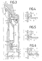
- FIG. 3 A third embodiment is shown in FIG. 3. This has an L-shaped closure member 8, which is held by an embedded spring 24 'in the first position as the rest position.
- the spring constant of this spring 24 ' is designed so that when the compression chamber 11 is vented, the pressure in the pressure chamber 3 presses the closure member 8 into the second position in which the inflow opening 7 is closed and the opening 10 is opened at the same time.
- the ventilation of the compression space 11 is brought about by the fact that the floor 2 runs in the course of its switching-on movement over a recess 22 arranged on the compression cylinder 17 and / or on the drive rod 19. This recess 22 must be arranged so that the ventilation takes place when the switch contacts 20, 21 are at a sufficient distance to achieve an arc extinguishing.
- 3 shows the position at which the ventilation of the compression space 11 begins.
- the bottom 2 in FIG. 3 is provided with a ventilation hole 15, which is closed by a check valve 16 during the switch-off movement.
- Check valve 16 and ventilation hole 15 serve to vent the compression chamber 11 during the switch-on movement.
- the ventilation hole 15 with the check valve 16 at another point, for. B. be arranged on the compression cylinder 17 so that the bore 15 opens into a part of the compression space 11, which is still retained in the off position.
- a check valve 27 is provided in the area of the opening 10 of the gas storage space 9, which prevents insulating gas from flowing back through the opening 10 into the gas storage space 9. This check valve is used when switching small currents to prevent a pressure loss of the pressure chamber 3 through the opening 10 into the gas storage space 9 during the second phase of the switch-off movement.
- the check valve 6 of the outflow opening 5 has an additional valve plate 6 ', which closes the cross section of the inlet 26 between the switching path 4 and the gas storage space 9 when the check valve 6 is open.
- This valve plate 6 ' ensures that the hot gas which has entered the gas storage space 9 as a result of strong gas expansion when the current approaches zero crossing and the resulting opening of the check valve 6 cannot flow back in the direction of the switching path 4, which causes mixing with the cold gas would result from the pressure chamber 3 and thereby deteriorate the extinguishing properties of this gas.
- Fig. 4 shows the closure member 8 'formed as at least one flap that closes the opening 10 in the first position and opens the inflow opening 7 to the pressure chamber 3 and the inflow in the second position Closes opening 7 and opens opening 10 to pressure chamber 3.
- the flap-shaped closure member 8 ' can be arranged, for example, with its fulcrum in the region of the drive rod 9, so that it rests in a horizontal position on the floor 1 and closes the opening 7 and at the same time opens the opening 10 to the pressure chamber 3.
- Fig. 5 shows the formation of the closure member 8 ⁇ as a sliding ring.
- This displaceable ring has a sliding surface on the inside to the drive rod 19, which is gas-tight.
- the closure member 8 ⁇ is drawn in its second position, in which it rests with its outer end on the floor 1 and thereby closes the inflow opening 7.
- the closure member 8 ⁇ is moved upward and abuts with its outer end on the partition wall 25, whereby the inflow opening 7 is connected to the pressure chamber 3 and closes the opening 10.
- the closure member 8 ⁇ is also designed as a displaceable ring, with the difference that the displaceable ring has a more plate-like shape and the inflow opening 7 can be arranged further out as seen from the axis of symmetry.
- the closure member 8 ⁇ is also in one position on the floor 1, closes the opening 7 and strikes in its other position on the partition 25, whereby the opening 10 is closed, the other opening being opened.
- closure members 8 'and 8 ⁇ are controlled by the pressures. Both during the first phase of the switch-off movement with high-current arcs and during the entire switch-off movement with low-current arcs, the strongest pressure P 3 occurs in the compression space 11. Characterized the closure members 8 ', 8, are pressed into their first position, in which they strike the partition 25 and thereby close the opening 10.
- the gas can flow from the compression space 11 into the pressure chamber 3.
- the expanding gas flows into the gas storage space 9 and from there to the opening 10.
- the pressure P2 thereby becomes higher than the pressures P1 and P3, so that the closure member 8 'or 8 ⁇ is pressed into its second position in which it rests on the bottom 1 and thereby closes the inflow opening 7 and opens the opening 10 to the pressure chamber 3.
- the pressure wave can flow into the pressure chamber 3 for post-compression.
- closure member 8 'or 8' is controlled by the gas pressure wave itself, which means that the transition from the first phase of the opening movement into the second phase of the opening movement is controlled by the gas pressure wave according to the arc formed in each case .
- a spring can be arranged which the closure member 8 ', 8 ⁇ holds in their first or second position. Presses z. B. a spring the closure member 8 ', 8 ⁇ against the bottom 1, the closure member 8', 8 ⁇ is already adjusted when the pressure P2 has almost reached the pressure P3. An inverted spring causes an adjustment of the closure member 8 ', 8 ⁇ takes place only when the pressure P2 is above the pressure P3 according to the spring strength.
- Another advantage of the design of the closure member according to Fig. 4 to Fig. 6 is that when switching low-current arcs, penetration of gas into the gas storage space 9 is prevented through the opening 10, since the closure member 8 ', 8' in its first Position remains.
- an embodiment of the closure member as shown in FIGS. 4 to 6, can be connected to one of the aforementioned vents of the compression space 11, this ventilation being controlled in such a way that the compression space 11 is vented when the switching movement is so advanced that further compression of the gas can no longer benefit the arc quenching.
- a faster switching movement is achieved in the final phase of the switch-off even if the current strength is too low for the formation of a gas pressure wave, as a result of which additional security against re-ignition of the arc is achieved even with such currents.
Landscapes
- Circuit Breakers (AREA)
Abstract
Description
Die Erfindung betrifft einen SF₆-Eindruckschalter mit einer mit Isoliergas gefüllten Schaltkammer, mindestens zwei Schaltstücken, von denen mindestens eines durch eine Antriebsstange bewegbar ist, einer durch diese Schaltbewegung betätigbaren Kompressionseinrichtung für das Isoliergas deren Kompressionsraum von zwei gegenüberliegenden, relativ zueinander bewegbaren Böden begrenzt ist.The invention relates to an SF₆ impression switch with a switching chamber filled with insulating gas, at least two switching pieces, at least one of which is movable by a drive rod, a compression device for the insulating gas which can be actuated by this switching movement and whose compression space is delimited by two opposite, relatively movable floors.
Hochspannungsschalter sind heute in der Regel als mit Isoliergas gefüllte Selbstblasschalter ausgeführt. In einer solchen mit Isoliergas gefüllten Schaltkammer werden die Kontakte getrennt und wird der Lichtbogen bis zum Erlöschen mit dem Isoliergas, meistens SF₆, beblasen. Die für diese Beblasung erforderliche Kompression wird entweder mittels einer Kompressionseinrichtung oder mittels der thermischen Energie des Lichtbogens selbst erzielt. Die Schaltkammern werden entweder von einem vollisolierten Metallgehäuse oder von einem Porzellanisolator umgeben.Today, high-voltage switches are usually designed as auto-blow switches filled with insulating gas. In such a switching chamber filled with insulating gas, the contacts are separated and the arc is blown with the insulating gas, usually SF₆, until it goes out. The compression required for this blowing is achieved either by means of a compression device or by means of the thermal energy of the arc itself. The interrupters are either surrounded by a fully insulated metal housing or by a porcelain insulator.
Aus der Firmenschaft der AEG "Hochleistungsschalter Autopneumatik" ist ein SF₆-Eindruckschalter bekannt, der eine mit Isoliergas gefüllte Schaltkammer aufweist, in der sich zwei Schaltstücke befinden, von denen eines feststehend und das andere mit der Schaltbewegung verschiebbar ist. Durch die Schaltbewegung wird eine Kompressionseinrichtung betätigt, die aus einem Kompressionskolben und einem Kompressionszylinder mit Zylinderboden be steht. Durchlässe in diesem Zylinderboden verbinden den Kompressionsraum mit einer Druckkammer, die von einer Isolierstoffdüse umgeben ist. Lichtbögen, deren Stromstärke im unteren und mittleren Bereich liegen, werden dadurch gelöscht, daß die Kompressionseinrichtung Löschgas komprimiert und durch die Durchlässe im Zylinderboden in die Druckkammer bläst, wodurch eine starke Löschgasströmung in der Düse entsteht, die den Lichtbogen im Stromnulldurchgang zum Erlöschen bringt.From the company of the AEG "high-performance switch autopneumatics" an SF₆ impression switch is known, which has a switching chamber filled with insulating gas, in which there are two contact pieces, one of which is stationary and the other is displaceable with the switching movement. The switching movement actuates a compression device, which consists of a compression piston and a compression cylinder with a cylinder base stands. Passages in this cylinder base connect the compression chamber with a pressure chamber, which is surrounded by an insulating material nozzle. Arcs, the current strength of which are in the lower and middle range, are extinguished by the compression device compressing extinguishing gas and blowing it through the passages in the cylinder bottom into the pressure chamber, as a result of which a strong flow of extinguishing gas arises in the nozzle, which extinguishes the arc at zero current.
Im Bereich stromschwächerer Lichtbögen, wie sie unter normalen Betriebsbedingungen auftreten, weist dieser SF₆-Eindruckschalter eine recht gute Funktion auf. Diese stromschwächeren Lichtbögen haben eine so geringe thermische Energie, daß es in der Druckkammer durch Erhitzung zu keiner nennenswerten Gasexpansion kommt. Es wird weder die Beblasung durch die Kompressionseinrichtung verhindert, noch die Schaltbewegung beeinträchtigt und damit die Schaltgeschwindigkeit vermindert. Es bildet sich auch keine größere Menge erhitzten Gases geringer Dichte, das die Beblasung des Lichtbogens beeinträchtigen könnte.In the area of low-current arcs, as they occur under normal operating conditions, this SF₆ impression switch has a very good function. These low-current arcs have such a low thermal energy that there is no significant gas expansion in the pressure chamber due to heating. Blowing by the compression device is neither prevented, nor is the switching movement impaired, and the switching speed is thus reduced. Neither does a large amount of heated, low density gas form which could interfere with the blowing of the arc.
Bei der Abschaltung stromstarker Lichtbögen, wie sie beispielsweise in Kurzschlußfällen auftreten, ist die Funktion dieses SF₆-Eindruckschalter nicht so optimal. Durch die hohe thermische Energie des Lichtbogens kommt es in der Druckkammer zu einer sehr starken Gasexpansion infolge der Erhitzung. Bei diesen stromstarken Lichtbögen trägt zur Löschung der Lichtbögen dieses expandierte, unter sehr hohem Druck stehende Gas wesentlich bei. Das unter sehr hohem Druck stehende Gas dringt jedoch auch durch die Durchlässe des Zylinderbodens in den Kompressionsraum des Kompressionszylinders ein und führt dadurch zu einer Verlangsamung der Schaltbewegung, bei sehr stromstarken Lichtbögen sogar zu einer kurzzeitigen Rückwärtsbewegung. Das in den Kompressionsraum eingedrungene Gas geht für den Löschvorgang verloren, da die Löschung des Lichtbogens im Stromnulldurchgang erfolgen muß, der Kompressionszylinder das in ihn eingedrungene Gas jedoch erst dann wieder ausstößt, wenn der hohe Druck in der Druckkammer wieder abgebaut ist. Dies ist jedoch erst nach dem Erlöschen des Lichtbogens der Fall.When switching off high-current arcs, such as occur in short-circuit cases, the function of this SF₆ impression switch is not so optimal. The high thermal energy of the arc leads to a very strong gas expansion in the pressure chamber due to the heating. With these high-current arcs, this expanded gas, which is under very high pressure, contributes significantly to extinguishing the arcs. However, the gas, which is under very high pressure, also penetrates through the passages of the cylinder base into the compression space of the compression cylinder and thus slows down the switching movement, and in the case of very powerful arcs, even leads to a brief backward movement. The gas that has entered the compression space is lost to the quenching process because the arc must be quenched at zero current, but the compression cylinder only ejects the gas that has entered it when the high pressure in the pressure chamber is reduced again. However, this is only the case after the arc has extinguished.
Ein weiterer Nachteil, insbesondere bei der Abschaltung stromstarker Lichtbögen, besteht darin, daß bei solchen SF₆-Eindruckschalter das heiße und das kalte Isoliergas im Gasspeicherraum vermischt werden, wobei sich eine mittlere Temperatur einstellt. Das zur Beblasung des Lichtbogens zur Isolierstoffdüse zurückströmende Isoliergas weist daher eine dieser erhöhten Temperatur entsprechende Dichte auf, welche gegenüber der Dichte des kalten Gases reduziert ist. Isoliergas mit einer solchen verringerten Dichte weist jedoch erheblich verschlechterte Löscheigenschaften auf.Another disadvantage, especially when switching off high-current arcs, is that the hot and cold insulating gas in the gas storage space are mixed in such SF₆ impression switches, with an average temperature being established. The insulating gas flowing back to blow the arc to the insulating material nozzle therefore has a density corresponding to this elevated temperature, which is reduced compared to the density of the cold gas. Insulating gas with such a reduced density, however, has considerably poorer extinguishing properties.
Zusammenfassend kann also festgestellt werden, daß der bekannte SF₆-Eindruckschalter bei Schaltvorgängen mit stromstarken Lichtbögen in dreierlei Hinsicht Nachteile aufweist:
- Der Schaltvorgang wird gebremst.
- Ein Teil des expandierenden Löschgases geht für die Beblasung verloren.
- Durch die starke Mischung von kalten Löschgas mit heißen Löschgas sind die Löscheigenschaften vermindert.In summary, it can be said that the known SF₆ indentation switch has disadvantages in three ways in switching operations with high-current arcs:
- The switching process is braked.
- Part of the expanding extinguishing gas is lost for the blowing.
- The strong mixture of cold extinguishing gas with hot extinguishing gas reduces the extinguishing properties.
Der Erfindung liegt daher die Aufgabe zugrunde, einen SF₆-Eindruckschalter verfügbar zu machen, der zur Lichtbogenlöschung bei stromstarken Lichtbögen zusätzlich die Lichtbogenenergie ausnutzt, eine Beblasung mit kaltem Isoliergas hoher Dichte gewährleistet und eine Rückwirkung der Lichtbogenenergie auf den Antrieb verhindert.The invention is therefore based on the object to make an SF₆ impression switch available, which additionally uses the arc energy for arc extinguishing in the case of high-current arcs, ensures blowing with cold insulating gas of high density and prevents the arc energy from reacting to the drive.
Diese Aufgabe wird erfindungsgemäß dadurch gelöst, daß zwischen der Isolierstoffdüse und dem ihr zugewandten Boden eine Druckkammer angeordnet ist, welche in Richtung der Schaltstrecke eine durch ein Rückschlagventil verschließbare Ausströmöffnung aufweist, daß im Boden eine mittels eines Verschlußorgans verschließbare Einströmöffnung angeordnet ist, daß ein mit der Schaltstrecke verbundener Gasspeicherraum sich bis zu einer mittels des Verschlußorgans verschließbaren Öffnung erstreckt, welche in den der Ausströmöffnung abgewandten Teil der Druckkammer mündet, daß in einer ersten Position des Verschlußorgans die Einströmöffnung geöffnet und die Öffnung verschlossen ist und daß in einer zweiten Position des Verschlußorgans die Einströmöffnung geschlossen und die Öffnung geöffnet ist, wobei die Positionsänderung des Verschlußorgans durch den zurückgelegten Schaltweg oder durch die auftretenden Drücke steuerbar ist.This object is achieved in that a pressure chamber is arranged between the insulating nozzle and the bottom facing it, which has an outflow opening that can be closed by a non-return valve in the direction of the switching path, that an inflow opening that can be closed by means of a closure member is arranged in the bottom, that a with the Switching path connected gas storage space extends to an opening which can be closed by means of the closure member, which opens into the part of the pressure chamber which faces away from the outflow opening, that in a first position of the closure member the inflow opening is opened and the opening is closed, and that in a second position of the closure member the inflow opening is closed and the opening is open, the change in position of the closure member being controllable by the switching path covered or by the pressures occurring.
Bei der Erfindung handelt es sich um eine Synthese des von der P 37 20 816 vorgeschlagenen SF₆-Eindruckschalter mit dem von der P 37 32 137 vorgeschlagenen Selbstblasschalter mit Gasspeicherraum. Durch diese Synthese zweier Schalter, die auf völlig verschiedenen Funktionsprinzipien beruhen, ist es nicht nur gelungen, deren Vorteile in einem Schalter zu vereinigen, sondern es werden noch neue Vorteile erzielt.The invention is a synthesis of the SF₆ impression switch proposed by P 37 20 816 with the auto-blow switch with gas storage space proposed by P 37 32 137. This synthesis of two switches, which are based on completely different functional principles, not only succeeded in combining their advantages in one switch, but new advantages are also achieved.
Der erfindungsgemäße SF₆-Eindruckschalter hat vor allem den Vorteil, bei stromschwächeren Lichtbögen eine Beblasung vorzunehmen, wie sie bei herkömmlichen SF₆-Eindruckschalter in zweckmäßiger und erprobter Weise erfolgt, sich jedoch bei stromstarken Lichtbögen voll auf die wesentlich erhöhten Anforderungen einzustellen. Zur Beblasung dieser stromstarken Lichtbögen wird das Gas durch eine Kompressionseinrichtung vorkomprimiert, wodurch ein Gaspolster kalten Löschgases hoher Dichte entsteht. Dieses Gaspolster wird durch die Gasdruckwelle, welche die Gasexpansion des stromstarken Lichtbogens hervorruft, nachkomprimiert. Dieses Nachkomprimieren erfolgt in der Art, daß das heiße Gas zuerst im Gasspeicherraum gekühlt wird und dann in die Druckkammer so einströmt, daß in dieser eine Schichtung entsteht, bei der das vorkomprimierte kältere Gaspolster hoher Dichte als erstes zur Beblasung zur Verfügung steht. Das gekühlte Gas bildet, da es erst nach dem Komprimieren des kaltes Gases einströmt, eine Schicht im unteren Teil der Druckkammer. Es dient primär der Druckerhöhung und wird erst zu einer Nachbeblasung nach Erlöschen des Lichtbogens herangezogen, um ein Wiederzünden zu vermeiden. Die Beblasung beginnt, sobald eine zur Lichtbogenlöschung ausreichende Distanz zwischen den Schaltkontakten erreicht ist.The SF₆ impression switch according to the invention has the advantage, above all, of carrying out blowing in the case of weaker electric arcs, as is done in a conventional and expedient manner in conventional SF₆ impression switches, but to adjust fully to the significantly increased requirements in the case of high-current arcs. To blow these powerful arcs, the gas is pre-compressed by a compression device, which creates a gas cushion of cold, high-density quenching gas. This gas cushion is post-compressed by the gas pressure wave, which causes the gas expansion of the high-current arc. This post-compression takes place in such a way that the hot gas is first cooled in the gas storage space and then flows into the pressure chamber in such a way that a stratification is formed in it, in which the pre-compressed, high-density gas cushion is first available for blowing. The cooled gas forms a layer in the lower part of the pressure chamber, since it only flows in after the cold gas has been compressed. It primarily serves to increase the pressure and is only used for post-blowing after the arc has been extinguished in order to avoid reignition. The blowing begins as soon as a sufficient distance between the switch contacts to extinguish the arc is reached.
Die Erfindung hat den weiteren Vorteil, daß keine Verminderung der Schaltgeschwindigkeit durch Eindringen von Gas in den Kompressionsraum infolge der Gasexpansion durch stromstarke Lichtbögen mehr eintritt. Durch das Nachkomprimieren in der Druckkammer mittels des expandierenden Gases steht diese Energie zur Beblasung der stromstarken Lichtbögen weiter zur Verfügung und wirkt sich nicht bremsend auf den Antrieb aus. Dies führt zu einer sicheren Löschung des Lichtbogens durch eine höhere Schaltgeschwindigkeit und eine bessere Beblasung mit einem Gas, das eine optimale Dichte aufweist.The invention has the further advantage that there is no further reduction in the switching speed due to the penetration of gas into the compression space as a result of the gas expansion by means of high-current arcs. As a result of the post-compression in the pressure chamber by means of the expanding gas, this energy is still available for blowing the high-current arcs and does not have a braking effect on the drive. This leads to a safe extinguishing of the arc by a higher switching speed and better blowing with a gas that has an optimal density.
Auf diese Weise wird es möglich, ein wesentlich größeres Ausschaltvermögen zu erzielen oder die Antriebsenergie zu verringern. Es ist auch gegenüber herkömmlichen Schaltern mit gleicher Leistung möglich, den gesamten Schalter einschließlich Kompressionseinrichtung, Düse, Antrieb usw. wesentlich kleiner zu dimensionieren und auf diese Weise Raum, Energie und Material einzusparen.In this way it becomes possible to achieve a significantly greater breaking capacity or to reduce the drive energy. Compared to conventional switches with the same power, it is also possible to dimension the entire switch including the compression device, nozzle, drive, etc. much smaller and thus save space, energy and material.
Weiterbildungen und zweckmäßige Ausgestaltungen der Erfindung sind den Unteransprüchen zu entnehmen, wobei sich durch die zusätzlichen Merkmale und deren Kombinationen weitere Vorteile ergeben.Further developments and expedient refinements of the invention can be found in the subclaims, further advantages resulting from the additional features and their combinations.
Die Erfindung wird nachstehend anhand von in den Zeichnungen dargestellten Ausführungsbeispielen erläutert, wobei auf die weiteren Vorteile verwiesen wird.The invention is explained below with reference to exemplary embodiments shown in the drawings, reference being made to the further advantages.
Es zeigen
- Fig. 1 Teile eines Ausführungsbeispiels, wobei sich die Darstellung auf einen Schnitt bis zur Mittellinie (Rotationsachse) beschränkt,
- Fig. 2 ein weiteres Ausführungsbeispiel,
- Fig. 3 ein drittes Ausführungsbeispiel und
- Fig. 4, Fig. 5 und Fig. 6 Ausschnitte mit verschiedenen Ausgestaltungsmöglichkeiten des Ver schlußorgans.
- 1 shows parts of an exemplary embodiment, the illustration being limited to a section up to the center line (axis of rotation),
- 2 shows another embodiment,
- Fig. 3 shows a third embodiment and
- Fig. 4, Fig. 5 and Fig. 6 excerpts with different design options of the United closing organ.
Fig. 1 zeigt ein Ausführungsbeispiel, wobei der SF₆-Eindruckschalter in einer Teilansicht dargestellt ist, bei der die wesentlichen Teile mittels eines bis zur Rotationsachse reichenden Schnitts dargestellt sind.Fig. 1 shows an embodiment, the SF₆ impression switch is shown in a partial view, in which the essential parts are shown by means of a section extending to the axis of rotation.
Dieses Ausführungsbeispiel enthält einmal die bei einem SF₆-Eindruckschalter üblichen Teile:
2 Schaltstücke 20 und 21, welche bei der Öffnung des Schalters eine Schalt strecke 4 bilden. Von diesen Schaltstücken ist ein Schaltstück 20 fest und das andere Schaltstück 21 mittels einer Antriebsstange 19 durch den Antrieb von der Einschalt- in eine Ausschaltstellung (sowie umgekehrt) bringbar. Der in der Schaltstrecke 4 bei der Ausschaltung entstehende Lichtbogen 23 wird mittels einer Kompressionseinrichtung beblasen. Dabei wird ein Isoliergasstrom mittels einer Isolierstoffdüse 12 gezielt auf den in der Schaltstrecke 4 brennenden Lichtbogen 23 gerichtet. Diese Kompressionseinrichtung besteht, wie bei SF₆-Eindruckschalter üblich, aus einem Kompressionszylinder 17 und zwei Böden 1 und 2, die sich bei einer Ausschaltung aufeinanderzubewegen und so das Isoliergas in einem Kompressionsraum 11 komprimieren. Beim vorliegenden Ausführungsbeispiel ist der Kompressionszylinder 17 als feststehendes Teil mit dem Boden 2 verbunden und der Boden 1, welcher mit dem Schaltstück 21 und der Antriebsstange 19 in Verbindung steht, wird in den Kompressionszylinder 17 hineingezogen.This exemplary embodiment contains the parts that are customary in an SF₆ impression switch:
2 switching
Der Erzielung einer besonders wirksamen Beblasung stromstarker Lichtbögen sowie einer Verhinderung der Rückwirkung der Gasexpansion auf den Antrieb dienen folgende Teile:
Zwischen dem Boden 1 und der Isolierstoffdüse 12 befinden sich eine Druckkammer 3 und davon durch eine Trennwand 25 getrennt ein Gasspeicherraum 9. Die Druckkammer 3 ist in Richtung der Schaltstrecke 4 mit einer Ausströmöffnung 5 versehen, bei der ein Einströmen von durch den Lichtbogen erhitztem Isoliergas durch ein Rückschlagventil 6 verhindert wird. Der Gasspeicherraum 9 verfügt über einen Einlaß 26 in Richtung der Schaltstrecke 4 und über eine Öffnung 10, die in die Druckkammer 3 auf der der Ausströmöffnung 5 gegenüberliegenden Seite einmündet. Der Boden 1 ist mit einer Einströmöffnung 7 versehen, die den Kompressionsraum 11 mit der Druckkammer 3 verbindet. In dem Bereich der Öffnung 10 und der Einströmöffnung 7 ist ein Verschlußorgan 8 angeordnet. Dieses Verschlußorgan 8 in Fig. 1 als verschiebbarer Ring mit L-förmigem Querschnitt ausgebildet. Es kann zwei Positionen einnehmen: Eine erste Position in der der axiale Schenkel des Verschlußorgans 8 dichtend vor die Öffnung 10 geschoben ist und die Einströmöffnung 7 freigibt. In einer zweiten Position, in welcher sich das Verschlußorgan 8 in der Darstellung der Fig. 1 befindet, ist die Öffnung 10 freigegeben und die Einströmöffnung 7 durch den radialen Schenkel des Verschlußorgans 8 verschlossen. Wenn keine Druckunterschiede auf das Verschlußorgan 8 einwirken, wird es von einer Feder 24 in dieser zweiten, dargestellten Position gehalten. Der Boden 2 ist als feststehendes Bauteil ausgebildet, wobei die Antriebsstange 19 durch eine Bohrung dieses Bodens hindurchtritt und eine Dichtung für die Gasdichtheit dieses Durchtritts sorgt. Im Boden 2 ist eine Entlüftungsbohrung 13 angeordnet, welche mit einem Entlüftungsventil 14 versehen ist, das gegen den Druck einer Feder 14′ öffnet. Desweiteren enthält der Boden 2 eine Belüftungsbohrung 15 mit einem Ventil 16, das so angeordnet ist, daß beim Einschaltvorgang eine Belüftung des Kompressionsraum 11 stattfindet.The following parts serve to achieve a particularly effective blowing of high-current arcs and to prevent the reaction of gas expansion to the drive:
A
Der dargestellte SF₆-Eindruckschalter weist folgende Funktionen auf:
Bei der Abschaltung schwacher Ströme entspricht die Funktion der aus herkömmlichen SF₆-Eindruckschalter bekannten:
Das Gas wird durch die Schaltbewegung, vermittelt durch die Antriebsstange 19, zwischen dem mit der Antriebsstange 19 verbundenen Boden 1 und dem feststehenden Boden 2 im Kompressionsraum 11 komprimiert, tritt durch die Einströmöffnung 7 hindurch und strömt über die Öffnung 5 zum Lichtbogen 23, um diesen im Nulldurchgang zu beblasen.The SF₆ impression switch shown has the following functions:
When switching off low currents, the function corresponds to that known from conventional SF₆ impression switches:
The gas is compressed by the switching movement, mediated by the
Im Unterschied zu den herkömmlichen SF₆-Eindruckschalter öffnet das Löschgas auf diesem Weg das Verschlußorgan 8, strömt durch die Druckkammer 3 hindurch und erreicht nach Verlassen der Druckkammer 3 durch die Ausströmöffnung 5 schließlich die Schaltstrecke 4 um den Lichtbogen 23 zu beblasen. Ein Verschluß der Ausströmöffnung 5 durch das Rückschlagventil 6 erfolgt nicht, da bei stromschwachen Lichtbögen keine so starke Gasdruckwelle entsteht, daß sich eine Gasströmung ausbildet, welche von der Schaltstrecke in Richtung der Kompressionseinrichtung fließt.In contrast to the conventional SF₆ impression switch, the quenching gas opens the
Bei der Ausschaltung stromstarker Lichtbögen paßt sich der SF₆-Eindruckschalter den durch die Gasexpansion verursachten Bedingungen an und nützt diese Gasexpansion für die Herstellung des erforderlichen Isoliergasdrucks aus:
Während der ersten Phase der Ausschaltbewegung wird in der oben beschriebenen Art und Weise im Kompressionsraum 11 Isoliergas komprimiert, strömt durch die Einströmöffnung 7 in die Druckkammer 3, wobei das Verschlußorgan 8 durch die Gasströmung geöffnet wird. Während dieser ersten Phase der Ausschaltbewegung wird der Lichtbogen 23 in der Schaltstrecke 4 gezogen, wodurch Löschgas expandiert und, wie durch den gebogenen Pfeil dargestellt, in Richtung der Kompressionseinrichtung fließt. Dies hat zur Folge, daß die Ausströmöffnung 5 durch das Rückschlagventil 6 verschlossen wird und das unter Druck stehende Gas in den Gasspeicherraum 9 fließt. Während dieser Phase der Ausschaltbewegung herrschen durch das geschlossene Rückschlagventil 6 in der Druckkammer 3 und dem Kompressionsraum 11 reproduzierbare Druckbedingungen, so daß ein bestimmter Druck einer bestimmten Distanz zwischen den Schaltkontakten 21 und 22 zuzuordnen ist. Dadurch kann die Federkonstante der Feder 14′ so ausgelegt werden, daß das Entlüftungsventil 14 in der Schaltstellung öffnet, in der die Schaltkontakte 20, 21 die zur Lichtbogenlöschung ausreichende Distanz erreicht haben. Durch die Öffnung des Entlüftungsventils 14 sinkt der Druck im Kompressionsraum 11 stark ab, was zur Folge hat, daß das Verschlußorgan 8 sich in die Position begibt, in der es mit seinem radialen Schenkel die Einströmöffnung 7 verschließt und gleichzeitig die Öffnung 10 freigibt. Durch die Entlüftung des Kompressionsraums 11 und die Positionsänderung des Verschlußorgans 8 tritt der SF₆-Eindruckschalter in seine zweite Phase der Ausschaltung. In dieser zweiten Phase der Ausschaltung ist der Antrieb von der Druckkraft im Kompressionsraum 11 durch dessen Entlüftung völlig entlastet, so daß es zu keiner Bremsung der Schaltbewegung oder gar einer Rückwärtsbewegung kommt, im Gegenteil - es tritt sogar eine Beschleunigung der Schaltbewegung durch die Entlastung ein. Vorteilhafterweise muß der Antrieb dadurch neben der Beschleunigung der entsprechenden Schalterteile nur die Energie für die Vorkompression des Gases in der Druckkammer 3 aufbringen. In der zweiten Phase der Ausschaltbewegung strömt das expandierte, im Gasspeicherraum 9 gespeicherte und dabei gekühlte Gas durch die Öffnung 10 in die Druckkammer 3. Das in der Druckkammer 3 vorkomprimierte kalte Gas wird durch die Gasdruckwelle, welche vom Gasspeicherraum 9 kommt, nachkomprimiert, wobei das kalte Gas hoher Dichte vor der Ausströmöffnung 5 liegt, um in dem für die Löschung des Lichtbogens entscheidenden Moment des Stromnulldurchgangs der Beblasung zu dienen. Bei Annäherung des Stromes des Lichtbogens an den Nulldurchgang läßt der durch den Lichtbogen 23 erzeugte Gasdruck nach, das Rückschlagventil 6 öffnet sich und das kalte Gaspolster strömt aus der Ausströmöffnung 5 aus in Richtung der Schaltstrecke 4, um dort den Lichtbogen zu beblasen. Auf diese Weise wurden bei gleichzeitiger Entlastung des Antriebs optimale Löschbedingungen geschaffen.When switching off high-current arcs, the SF₆ impression switch adapts to the conditions caused by the gas expansion and uses this gas expansion to produce the required insulating gas pressure:
During the first phase of the switch-off movement, insulating gas is compressed in the
Fig. 2 zeigt ein Ausführungsbeispiel, bei dem der Kompressionszylinder 17 mit dem Boden 1 fest verbunden ist und durch die von der Antriebsstange 19 vermittelte Schaltbewegung über den feststehenden Boden 2 gezogen wird. Bei dieser Ausbildung wird das Entlüftungsventil 14 gegen die Kraft einer Feder 14˝ durch einen Stift 18 geöffnet. Die Länge dieses Stifts 18 ist so bemessen, daß das Entlüftungsventil 14 beim Erreichen einer zur Lichtbogenlöschung ausreichenden Distanz zwischen den Schaltkontakten 20 und 21 die Ventilplatte des Entlüftungsventils 14 aus ihrer Schließstellung hebt. Die Feder 14˝ muß eine größere Federkonstante aufweisen als die in Fig. 1 beschriebene Feder 14′. Das Verschlußorgan 8 ist ebenfalls als L-förmiger Ring ausgebildet, wobei jedoch der axiale Schenkel länger ist und durch Bohrungen die Öffnung 10 in der zweiten Position freigibt. Die übrigen Teile entsprechen von ihrem Aufbau und ihrer Funktion dem zu Fig. 1 bereits beschriebenen.Fig. 2 shows an embodiment in which the
Die Fig. 2 dient dazu, deutlich zu machen, daß abweichende Ausgestaltungen der Böden 1 und 2 sowie des Zylinders 17 und der Steuerung des Verschlußorgans 8 möglich sind. Es sind jedoch noch weitere abweichende Ausgestaltungen denkbar, zum Beispiel eine Ausgestaltung, bei der die Antriebsstange mit dem Boden 2 und dem Schaltstück 20 verbunden ist und die übrigen Teile feststehen.Fig. 2 serves to make it clear that different configurations of the
Ein drittes Ausführungsbeispiel ist in Fig. 3 dargestellt. Dies weist ein L-förmiges Verschlußorgan 8 auf, welches durch eine eingelagerte Feder 24′ in der ersten Position als Ruhelage gehalten wird. Die Federkonstante dieser Feder 24′ ist so ausgelegt, daß bei einer Entlüftung des Kompressionsraums 11 der Druck in der Druckkammer 3 das Verschlußorgan 8 in die zweite Position drückt, in der die Einströmöffnung 7 verschlossen ist und die Öffnung 10 gleichzeitig geöffnet wird. Die Entlüftung des Kompressionsraums 11 wird dadurch bewirkt, daß der Boden 2 im Zuge seiner Einschaltbewegung über eine am Kompressionszylinder 17 und/oder an der Antriebsstange 19 angeordnete Aussparung 22 läuft. Diese Aussparung 22 muß so angeordnet sein, daß die Belüftung dann stattfindet, wenn die Schaltkontakte 20, 21 eine zu Erreichung einer Lichtbogenlöschung ausreichende Distanz aufweisen. In der Fig. 3 ist die Position dargestellt, bei der die Entlüftung des Kompressionsraums 11 beginnt.A third embodiment is shown in FIG. 3. This has an L-shaped
Wie schon bei der Fig. 1 und 2 ist auch in Fig. 3 der Boden 2 mit einer Belüftungsbohrung 15 versehen, die bei der Ausschaltbewegung durch ein Rückschlagventil 16 verschlossen ist. Rückschlagventil 16 und Belüftungsbohrung 15 dienen der Belüftung des Kompressionsraums 11 bei der Einschaltbewegung. Selbstverständlich kann die Belüftungsbohrung 15 mit dem Rückschlagventil 16 auch an einer anderen Stelle, z. B. am Kompressionszylinder 17 so angeordnet werden, daß die Bohrung 15 in einen Teil des Kompressionsraums 11 mündet, der auch in der Ausschaltstellung noch erhalten bleibt.As in FIGS. 1 and 2, the
Beim Ausführungsbeispiel der Fig. 3 ist im Bereich der Öffnung 10 des Gasspeicherraums 9 ein Rückschlagventil 27 vorgesehen, das ein Rückströmen von Isoliergas durch die Öffnung 10 in den Gasspeicherraum 9 verhindert. Dieses Rückschlagventil dient bei der Schaltung kleiner Ströme dazu, während der zweiten Phase der Ausschaltbewegung einen Druckverlust der Druckkammer 3 durch die Öffnung 10 in den Gasspeicherraum 9 zu verhindern.In the embodiment of FIG. 3, a
Das Rückschlagventil 6 der Ausströmöffnung 5 weist eine zusätzliche Ventilplatte 6′ auf, die bei geöffneten Rückschlagventil 6 den Querschnitt des Einlasses 26 zwischen der Schaltstrecke 4 und dem Gasspeicherraum 9 verschließt. Diese Ventilplatte 6′ sorgt dafür, daß das infolge starker Gasexpansion in den Gasspeicherraum 9 eingedrungene heiße Gas bei Annäherung des Stromes an den Nulldurchgang und der dadurch bedingten Öffnung des Rückschlagventils 6 nicht in Richtung der Schaltstrecke 4 zurückfluten kann, was eine Vermischung mit dem kalten Gas aus der Druckkammer 3 zur Folge hätte und dadurch die Löscheigenschaften dieses Gases verschlechtern würde.The
Die Fig. 4 bis 6 zeigen jeweils einen Ausschnitt des SF₆-Eindruckschalters im Bereich zwischen der Antriebsstange 19, der Zwischenwand 25 und dem Boden 1. Dargestellt ist das Verschlußorgan 8′ bzw. 8˝ in verschiedenen Ausgestaltungsmöglichkeiten.4 to 6 each show a section of the SF₆ impression switch in the area between the
Fig. 4 zeigt das Verschlußorgan 8′ als mindestens eine Klappe ausgebildet, die in der ersten Position die Öffnung 10 verschließt und die Einströmöffnung 7 zur Druckkammer 3 öffnet und in der zweiten Position die Einström öffnung 7 verschließt und die Öffnung 10 zur Druckkammer 3 öffnet. Dazu kann das klappenförmig ausgebildete Verschlußorgan 8′ beispielsweise mit seinem Drehpunkt im Bereich der Antriebsstange 9 angeordnet werden, so daß es in einer waagerechten Stellung auf dem Boden 1 aufliegt und die Öffnung 7 verschließt und dabei gleichzeitig die Öffnung 10 zur Druckkammer 3 freigibt. In seiner angehobenen Stellung schlägt das klappenförmig ausgebildete Verschlußorgan 8′ an der Trennwand 25 an, verschließt dadurch die Öffnung 10 und gibt die Einströmöffnung 7 zur Druckkammer 3 frei.Fig. 4 shows the closure member 8 'formed as at least one flap that closes the
Fig. 5 zeigt die Ausbildung des Verschlußorgans 8˝ als ein verschiebbarer Ring. Dieser verschiebbare Ring weist an der Innenseite zur Antriebsstange 19 eine Gleitfläche auf, die gasdicht ausgebildet ist. Das Verschlußorgan 8˝ ist in seiner zweiten Position gezeichnet, in der es mit seinem äußeren Ende auf dem Boden 1 aufliegt und dadurch die Einströmöffnung 7 verschließt. In seiner zweiten Position wird das Verschlußorgan 8˝ nach oben verschoben und stößt mit seinem äußeren Ende an die Trennwand 25 an, wodurch die Einströmöffnung 7 mit der Druckkammer 3 verbunden ist und die Öffnung 10 verschließt.Fig. 5 shows the formation of the
Eine ähnliche Funktion weist Fig. 6 auf. Das Verschlußorgan 8˝ ist ebenfalls als verschiebbarer Ring ausgebildet, mit dem Unterschied, daß der verschiebbare Ring eine mehr plattenförmige Gestalt hat und die Einströmöffnung 7 dadurch von der Symmetrieachse gesehen weiter außen angeordnet werden kann. Das Verschlußorgan 8˝ liegt ebenfalls in einer Position auf dem Boden 1 auf, verschließt dabei die Öffnung 7 und schlägt in seiner anderen Position an die Trennwand 25 an, wodurch die Öffnung 10 verschlossen wird, wobei jeweils die andere Öffnung geöffnet ist.6 has a similar function. The
Die gemäß den Fig. 4 bis 6 ausgebildeten Verschlußorgane 8′ und 8˝ werden von den Drücken gesteuert.
Sowohl während der ersten Phase der Ausschaltbewegung bei stromstarken Lichtbögen wie während der gesamten Ausschaltbewegung bei stromschwachen Lichtbögen tritt im Kompressionsraum 11 der stärkste Druck P₃ auf. Dadurch werden die Verschlußorgane 8′, 8˝ in ihre erste Position gedrückt, in der sie an die Trennwand 25 anschlagen und dadurch die Öffnung 10 verschließen.4 to 6 formed
Both during the first phase of the switch-off movement with high-current arcs and during the entire switch-off movement with low-current arcs, the
Das Gas kann aus dem Kompressionsraum 11 in die Druckkammer 3 strömen. Bei stromstarken Lichtbögen strömt das expandierende Gas in den Gasspeicherraum 9 und von dort zur Öffnung 10. Der Druck P₂ wird dadurch höher als die Drücke P₁ und P₃, so daß das Verschlußorgan 8′ bzw. 8˝ in seine zweite Position gedrückt wird, in der es am Boden 1 anliegt und dadurch die Einströmöffnung 7 verschließt und die Öffnung 10 zur Druckkammer 3 freigibt. Dadurch kann die Druckwelle in die Druckkammer 3 zur Nachkompression einströmen.The gas can flow from the
Der besondere Vorteil dieser Ausbildung liegt darin, daß das Verschlußorgan 8′ bzw. 8˝ durch die Gasdruckwelle selbst gesteuert wird, wodurch sich der Übergang von der ersten Phase der Ausschaltbewegung in die zweite Phase der Ausschaltbewegung gesteuert von der Gasdruckwelle nach dem jeweils ausgebildeten Lichtbogen richtet.The particular advantage of this design is that the closure member 8 'or 8' is controlled by the gas pressure wave itself, which means that the transition from the first phase of the opening movement into the second phase of the opening movement is controlled by the gas pressure wave according to the arc formed in each case .
Falls nach der jeweiligen Dimensionierung des Schalters, der Stärke des Antriebs, der Antriebsgeschwindigkeit oder den zu schaltenden Strömen sich eine verzögerte oder eine beschleunigte Reaktion des Verschlußorgans auf die Gasdruckwelle als zweckmäßig erweist, kann eine Feder angeordnet sein, die das Verschlußorgan 8′, 8˝ in ihrer ersten oder in ihrer zweiten Position hält. Drückt z. B. eine Feder das Verschlußorgan 8′, 8˝ gegen den Boden 1, so wird das Verschlußorgan 8′, 8˝ bereits dann verstellt, wenn der Druck P₂ nahezu den Druck P₃ erreicht hat. Eine umgekehrt angeordnete Feder bewirkt, daß eine Verstellung des Verschlußorgans 8′, 8˝ erst dann erfolgt, wenn der Druck P₂ entsprechend der Federstärke über den Druck P₃ liegt.If, after the respective dimensioning of the switch, the strength of the drive, the drive speed or the currents to be switched, a delayed or accelerated reaction of the closure member to the gas pressure wave proves to be expedient, a spring can be arranged which the
Ein weiterer Vorteil der Ausbildung des Verschlußorgans gemäß Fig. 4 bis Fig. 6 liegt darin, daß bei der Schaltung stromschwacher Lichtbögen ein Eindringen von Gas in den Gasspeicherraum 9 durch die Öffnung 10 verhindert ist, da das Verschlußorgan 8′, 8˝ in ihrer ersten Position bleibt.Another advantage of the design of the closure member according to Fig. 4 to Fig. 6 is that when switching low-current arcs, penetration of gas into the
Selbstverständlich sind Kombinationen der verschiedenen Ausgestaltungen möglich, wie den Rückbeziehungen der Unteransprüche zu entnehmen ist.Combinations of the various configurations are of course possible, as can be seen from the backward relationships of the subclaims.
Beispielsweise kann eine Ausbildung des Verschlußorgans, wie sie in den Fig. 4 bis 6 dargestellt ist, mit einer der vorgenannten Entlüftungen des Kompressionsraums 11 verbunden werden, wobei diese Entlüftung dann so gesteuert wird, daß es dann zu einer Entlüftung des Kompressionraum 11 kommt, wenn die Schaltbewegung so weit forgeschritten ist, daß ein weiteres Komprimieren des Gases nicht mehr der Löschung des Lichtbogens zugute kommen kann. Dadurch wird eine schnellere Schaltbewegung in der Endphase der Ausschaltung auch dann erreicht, wenn die Stromstärke für das Entstehen einer Gasdruckwelle zu gering ist, wodurch eine zusätzliche Sicherheit gegen ein Wiederzünden des Lichtbogens auch bei solchen Strömen erzielt wird.For example, an embodiment of the closure member, as shown in FIGS. 4 to 6, can be connected to one of the aforementioned vents of the
Claims (14)
dadurch gekennzeichnet, daß zwischen der Isolierstoffdüse (12) und dem ihr zugewandten Boden (1) eine Druckkammer (3) angeordnet ist, welche in Richtung der Schaltstrecke (4) eine durch ein Rückschlagventil (6) verschließbare Ausströmöffnung (5) aufweist, daß im Boden (1) eine mittels eines Verschlußorgans (8, 8′, 8˝) verschließbare Einströmöffnung (7) angeordnet ist, daß ein mit der Schaltstrecke (4) verbundener Gasspeicherraum (9) sich bis zu einer mittels des Verschlußorgans (8, 8′, 8˝) verschließbaren Öffnung (10) erstreckt, welche in den der Ausströmöffnung (5) abgewandten Teil der Druckkammer (3) mündet, daß in einer ersten Position des Verschlußorgans (8, 8′, 8˝) die Einströmöffnung (7) geöffnet und die Öffnung (10) verschlossen ist und daß in einer zweiten Position des Verschlußorgans (8, 8′, 8˝) die Einströmöffnung (7) geschlossen und die Öffnung (10) geöffnet ist, wobei die Positionsänderung des Verschlußorgans (8, 8′, 8˝) durch den zurückgelegten Schaltweg oder durch die auftretenden Drücke steuerbar ist.1. SF₆ impression switch with a switching chamber filled with insulating gas, at least two switching elements, at least one of which is movable by a drive rod, a compression device for the insulating gas which can be actuated by this switching movement and whose compression space is delimited by two opposite, relatively movable floors,
characterized in that between the insulating material nozzle (12) and the bottom (1) facing it a pressure chamber (3) is arranged, which in the direction of the switching path (4) has an outflow opening (5) which can be closed by a check valve (6) Bottom (1) an inflow opening (7) which can be closed by means of a closure member (8, 8 ', 8˝) is arranged such that a gas storage space (9) connected to the switching path (4) extends up to one by means of the closure member (8, 8' , 8˝) closable opening (10), which opens into the outflow opening (5) facing away from the pressure chamber (3), that in a first position of the closure member (8, 8 ', 8˝) opens the inflow opening (7) and the opening (10) is closed and that in a second position of the closure member (8, 8 ', 8˝) the inflow opening (7) is closed and the opening (10) is opened, the change in position of the closure member (8, 8' , 8˝) by the shift path covered or by the occurring pressures is controllable.
dadurch gekennzeichnet, daß das Verschlußorgan (8) als axial verschiebbarer Ring mit L-förmigem Querschnitt ausgebildet ist, wobei in der ersten Position des Verschlußorgans (8) der axiale Schenkel dichtend vor die Öffnung (10) geschoben und die Einströmöffnung (7) freigegeben ist und in der zweiten Position die Öffnung (10) freigegeben und die Einströmöffnung (7) durch den radialen Schenkel verschlossen ist, und daß die axiale Verschiebung des L-förmigen Rings durch eine Entlüftung des Kompressionsraums (11) bewirkt ist.2. SF₆ impression switch according to claim 1,
characterized in that the closure member (8) is designed as an axially displaceable ring with an L-shaped cross section, in the first position of the closure member (8) the axial leg sealingly pushed in front of the opening (10) and the inflow opening (7) being opened and in the second position, the opening (10) is opened and the inflow opening (7) is closed by the radial leg, and that the axial displacement of the L-shaped ring is brought about by venting the compression space (11).
dadurch gekennzeichnet, daß das Verschlußorgan (8′) als mindestens eine Klappe ausgebildet ist, derart, daß sie in der ersten Position die Öffnung (10) verschließt und die Einströmöffnung (7) öffnet und in der zweiten Position die Einströmöffnung (7) verschließt und die Öffnung (10) öffnet.3. SF₆ impression switch according to claim 1,
characterized in that the closure member (8 ') is designed as at least one flap, such that it closes the opening (10) in the first position and opens the inflow opening (7) and closes the inflow opening (7) in the second position and the opening (10) opens.
dadurch gekennzeichnet, daß das Verschlußorgan (8˝) als ein verschiebbarer Ring ausgebildet ist, der in der ersten Position die Öffnung (10) verschließt und die Einströmöffnung (7) öffnet und in der zweiten Position die Einströmöffnung (7) verschließt und die Öffnung (10) öffnet.4. SF₆ impression switch according to claim 1,
characterized in that the closure member (8˝) is designed as a displaceable ring which closes the opening (10) in the first position and opens the inflow opening (7) and closes the inflow opening (7) in the second position and closes the opening ( 10) opens.
dadurch gekennzeichnet, daß der Kompressionsraum (11) durch ein Entlüftungsventil (14) entlüftbar ist, dessen Schließfeder ( 14′) so ausgelegt ist, daß es bei einem Druck im Kompressionsraum (11) öffnet, der nur infolge des Verschließens der Einströmöffnung (7) auftreten kann.5. SF₆ impression switch according to claim 3 or 4,
characterized in that the compression space (11) can be vented through a vent valve (14), the closing spring (14 ') of which is designed so that it opens at a pressure in the compression space (11) which only results from the closing of the inflow opening (7) can occur.
dadurch gekennzeichnet, daß die Positionsänderung des Verschlußorgans (8′, 8˝) durch eine Entlüftung des Kompressionsraums bewirkt ist.6. SF₆ impression switch according to claim 3 or 4,
characterized in that the change in position of the closure member (8 ', 8˝) is effected by venting the compression space.
dadurch gekennzeichnet, daß die Entlüftung des Kompressionsraums (11) durch eine Entlüftungsbohrung (13) mit einem Entlüftungsventil (14) bewirkt ist, welches gegen die Kraft einer Feder (14′) öffnet, wobei die Federkonstante so bestimmt ist, daß die Öffnung des Entlüftungsventils (14) bei einem Druck im Kompressionsraum (11) stattfindet, der auftritt, wenn bei geschlossenem Rückschlagventil (6) die zur Lichtbogenlöschung ausreichende Distanz zwischen den Schaltkontakten (20, 21) erreicht ist.7. SF₆ impression switch according to claim 2 or 6,
characterized in that the ventilation of the compression space (11) is effected by a vent hole (13) with a vent valve (14) which opens against the force of a spring (14 '), the spring constant being determined such that the opening of the vent valve (14) takes place at a pressure in the compression space (11), which occurs when the distance between the switching contacts (20, 21) sufficient for arc quenching has been reached with the check valve (6) closed.
dadurch gekennzeichnet, daß das Entlüftungsventil (14) gegen die Kraft einer Feder (14˝) öffnet, deren Federkonstante größer als die der Feder (14′) ist, und daß mit dem Boden (1) ein Stift (18) verbunden ist, welcher in seiner Länge so bemessen ist, daß er das Entlüftungsventil (14) beim Erreichen einer zur Lichtbogenlöschung ausreichenden Distanz zwischen den Schaltkontakten (20, 21) öffnet.8. SF₆ impression switch according to claim 2 or 6,
characterized in that the vent valve (14) opens against the force of a spring (14˝), the spring constant of which is greater than that of the spring (14 '), and in that a pin (18) is connected to the bottom (1), which its length is such that it opens the vent valve (14) when it reaches a sufficient distance between the switching contacts (20, 21) for arc quenching.
dadurch gekennzeichnet, daß der Boden (1) beim Erreichen einer zur Lichtbogenlöschung ausreichenden Distanz zwischen den Schaltkontakten (20, 21) über eine am Kompressionszylinder (17) und/oder an der Antriebsstange (19) angeordnete Aussparung (22) läuft.9. SF₆ impression switch according to claim 2 or 6,
characterized in that the base (1) runs over a recess (22) arranged on the compression cylinder (17) and / or on the drive rod (19) when a sufficient distance for arc quenching is reached between the switching contacts (20, 21).
gekennzeichnet durch eine Feder (24), die das Verschlußorgan (8, 8′, 8˝) in der zweiten Position hält.10. SF₆ impression switch according to one or more of claims 1 to 9,
characterized by a spring (24) which holds the closure member (8, 8 ', 8˝) in the second position.
gekennzeichnet durch eine Feder (24′), die das Verschlußorgan in der ersten Position hält.11. SF₆ impression switch according to one or more of claims 1 to 9,
characterized by a spring (24 ') which holds the closure member in the first position.
dadurch gekennzeichnet, daß das Rückschlagventil (6) eine zusätzliche Ventilplatte (6′) aufweist, die bei geöffneten Rückschlagventil (6) den Querschnitt des Einlaßes (26) zwischen Schaltstrecke (4) und Gasspeicherraum (9) verschließt.12. SF₆ impression switch according to one or more of claims 1 to 11,
characterized in that the check valve (6) has an additional valve plate (6 ') which, when the check valve (6) is open, closes the cross section of the inlet (26) between the switching path (4) and the gas storage space (9).
dadurch gekennzeichnet, daß der Kompressionsraum (11) durch eine mit einem Rückschlagventil (16) versehene Belüftungsbohrung (15) bei der Einschaltbewegung belüftet wird.13. SF₆ impression switch according to one or more of claims 1 to 12,
characterized in that the compression space (11) is ventilated through a ventilation bore (15) provided with a check valve (16) during the switch-on movement.
dadurch gekennzeichnet, daß im Bereich der Öffnung (10) des Gasspeicherraums (9) ein Rückschlagventil (27) so angeordnet ist, daß durch die Öffnung (10) kein Isoliergas in den Gasspeicherraum (9) strömen kann.14. SF₆ impression switch according to one or more of claims 1, 2 or 7 to 13,
characterized in that a check valve (27) is arranged in the region of the opening (10) of the gas storage space (9) such that no insulating gas can flow into the gas storage space (9) through the opening (10).
Applications Claiming Priority (2)
| Application Number | Priority Date | Filing Date | Title |
|---|---|---|---|
| DE3810091A DE3810091A1 (en) | 1988-03-25 | 1988-03-25 | SF (DOWN ARROW) 6 (DOWN ARROW) PRESSURE SWITCH |
| DE3810091 | 1988-03-25 |
Publications (3)
| Publication Number | Publication Date |
|---|---|
| EP0334008A2 true EP0334008A2 (en) | 1989-09-27 |
| EP0334008A3 EP0334008A3 (en) | 1991-01-23 |
| EP0334008B1 EP0334008B1 (en) | 1992-04-22 |
Family
ID=6350663
Family Applications (1)
| Application Number | Title | Priority Date | Filing Date |
|---|---|---|---|
| EP89102110A Expired - Lifetime EP0334008B1 (en) | 1988-03-25 | 1989-02-08 | Single-pressure switch with sf6 |
Country Status (2)
| Country | Link |
|---|---|
| EP (1) | EP0334008B1 (en) |
| DE (2) | DE3810091A1 (en) |
Cited By (2)
| Publication number | Priority date | Publication date | Assignee | Title |
|---|---|---|---|---|
| EP1372172A1 (en) * | 2002-06-12 | 2003-12-17 | Alstom | Gas blast switch |
| CN102306590A (en) * | 2011-06-01 | 2012-01-04 | 厦门华电开关有限公司 | Arc extinguishing chamber of circuit breaker |
Families Citing this family (3)
| Publication number | Priority date | Publication date | Assignee | Title |
|---|---|---|---|---|
| DE3942489C2 (en) * | 1989-12-22 | 1994-03-10 | Licentia Gmbh | Gas pressure switch |
| FR2704976B1 (en) * | 1993-05-07 | 1995-06-23 | Gec Alsthom T & D Sa | HIGH OR MEDIUM VOLTAGE BLOW GAS CIRCUIT BREAKER. |
| DE19547522C1 (en) | 1995-12-08 | 1997-01-16 | Siemens Ag | HV line circuit breaker with gas-storage space - has gas-storage space divided by partition into heating space and cold gas space |
Citations (4)
| Publication number | Priority date | Publication date | Assignee | Title |
|---|---|---|---|---|
| CH568649A5 (en) * | 1974-07-29 | 1975-10-31 | Sprecher & Schuh Ag | |
| FR2563372A1 (en) * | 1984-04-24 | 1985-10-25 | Alsthom Atlantique | HIGH VOLTAGE ARC FLOW CIRCUIT BREAKER |
| EP0175954A2 (en) * | 1984-09-26 | 1986-04-02 | BBC Brown Boveri AG | Compressed gas circuit breaker |
| EP0239068A1 (en) * | 1986-03-26 | 1987-09-30 | Gec Alsthom Sa | Gas blast switch |
-
1988
- 1988-03-25 DE DE3810091A patent/DE3810091A1/en not_active Withdrawn
-
1989
- 1989-02-08 EP EP89102110A patent/EP0334008B1/en not_active Expired - Lifetime
- 1989-02-08 DE DE8989102110T patent/DE58901215D1/en not_active Expired - Fee Related
Patent Citations (4)
| Publication number | Priority date | Publication date | Assignee | Title |
|---|---|---|---|---|
| CH568649A5 (en) * | 1974-07-29 | 1975-10-31 | Sprecher & Schuh Ag | |
| FR2563372A1 (en) * | 1984-04-24 | 1985-10-25 | Alsthom Atlantique | HIGH VOLTAGE ARC FLOW CIRCUIT BREAKER |
| EP0175954A2 (en) * | 1984-09-26 | 1986-04-02 | BBC Brown Boveri AG | Compressed gas circuit breaker |
| EP0239068A1 (en) * | 1986-03-26 | 1987-09-30 | Gec Alsthom Sa | Gas blast switch |
Cited By (4)
| Publication number | Priority date | Publication date | Assignee | Title |
|---|---|---|---|---|
| EP1372172A1 (en) * | 2002-06-12 | 2003-12-17 | Alstom | Gas blast switch |
| CN102306590A (en) * | 2011-06-01 | 2012-01-04 | 厦门华电开关有限公司 | Arc extinguishing chamber of circuit breaker |
| WO2012163068A1 (en) * | 2011-06-01 | 2012-12-06 | 厦门华电开关有限公司 | Arc extinguishing chamber for circuit breaker |
| CN102306590B (en) * | 2011-06-01 | 2013-08-28 | 厦门华电开关有限公司 | Arc extinguishing chamber of circuit breaker |
Also Published As
| Publication number | Publication date |
|---|---|
| EP0334008A3 (en) | 1991-01-23 |
| EP0334008B1 (en) | 1992-04-22 |
| DE3810091A1 (en) | 1989-10-05 |
| DE58901215D1 (en) | 1992-05-27 |
Similar Documents
| Publication | Publication Date | Title |
|---|---|---|
| EP0067460B2 (en) | High-voltage power circuit breaker | |
| DE3247121C2 (en) | ||
| EP0766278A2 (en) | Circuit breaker | |
| DE60305552T2 (en) | High-voltage circuit breaker with a decompression valve for an arc-extinguishing heating chamber | |
| EP0296363B1 (en) | Circuit breaker with selfproduced flow of extinguishing gas | |
| DE2812945C2 (en) | Gas switch | |
| DE3915700C2 (en) | ||
| EP0334008B1 (en) | Single-pressure switch with sf6 | |
| EP0744759B1 (en) | H.T. circuit breaker with a fixed heating chamber | |
| DE4103119A1 (en) | EXHAUST GAS SWITCH | |
| EP0025833B1 (en) | Gas blast switch | |
| EP0959483B1 (en) | Load break switch with arc extinguishing chamber | |
| DE2811510C2 (en) | Electric pressure gas switch | |
| DE3930548C2 (en) | Gas pressure switch | |
| EP0456139B1 (en) | Compression switch | |
| EP0374384B1 (en) | Single-pressure switch with SF6 | |
| DE4025553C2 (en) | Gas pressure switch | |
| DE2635573A1 (en) | COMPRESSED GAS BLOW CIRCUIT BREAKER | |
| DE19524637C2 (en) | Gas pressure switch | |
| DE3843406A1 (en) | SF6 single-pressure circuit breaker (puffer circuit breaker) | |
| DE3843405C1 (en) | ||
| AT398140B (en) | EXHAUST GAS SWITCH | |
| DE2759265B2 (en) | Gas switch | |
| CH650100A5 (en) | Gas-blast circuit breaker | |
| EP4024425A1 (en) | Switching device with movable nozzle element |
Legal Events
| Date | Code | Title | Description |
|---|---|---|---|
| PUAI | Public reference made under article 153(3) epc to a published international application that has entered the european phase |
Free format text: ORIGINAL CODE: 0009012 |
|
| AK | Designated contracting states |
Kind code of ref document: A2 Designated state(s): CH DE FR IT LI SE |
|
| PUAL | Search report despatched |
Free format text: ORIGINAL CODE: 0009013 |
|
| AK | Designated contracting states |
Kind code of ref document: A3 Designated state(s): CH DE FR IT LI SE |
|
| 17P | Request for examination filed |
Effective date: 19910129 |
|
| 17Q | First examination report despatched |
Effective date: 19910722 |
|
| GRAA | (expected) grant |
Free format text: ORIGINAL CODE: 0009210 |
|
| AK | Designated contracting states |
Kind code of ref document: B1 Designated state(s): CH DE FR IT LI SE |
|
| REF | Corresponds to: |
Ref document number: 58901215 Country of ref document: DE Date of ref document: 19920527 |
|
| ET | Fr: translation filed | ||
| ITF | It: translation for a ep patent filed |
Owner name: MODIANO & ASSOCIATI S.R.L. |
|
| PLBE | No opposition filed within time limit |
Free format text: ORIGINAL CODE: 0009261 |
|
| STAA | Information on the status of an ep patent application or granted ep patent |
Free format text: STATUS: NO OPPOSITION FILED WITHIN TIME LIMIT |
|
| 26N | No opposition filed | ||
| EAL | Se: european patent in force in sweden |
Ref document number: 89102110.7 |
|
| REG | Reference to a national code |
Ref country code: CH Ref legal event code: PUE Owner name: LICENTIA PATENT- VERWALTUNGS-GMBH TRANSFER- AEG EN |
|
| REG | Reference to a national code |
Ref country code: FR Ref legal event code: TP |
|
| PGFP | Annual fee paid to national office [announced via postgrant information from national office to epo] |
Ref country code: FR Payment date: 20000215 Year of fee payment: 12 |
|
| PGFP | Annual fee paid to national office [announced via postgrant information from national office to epo] |
Ref country code: SE Payment date: 20000218 Year of fee payment: 12 Ref country code: CH Payment date: 20000218 Year of fee payment: 12 |
|
| PGFP | Annual fee paid to national office [announced via postgrant information from national office to epo] |
Ref country code: DE Payment date: 20000426 Year of fee payment: 12 |
|
| PG25 | Lapsed in a contracting state [announced via postgrant information from national office to epo] |
Ref country code: SE Free format text: LAPSE BECAUSE OF NON-PAYMENT OF DUE FEES Effective date: 20010209 |
|
| PG25 | Lapsed in a contracting state [announced via postgrant information from national office to epo] |
Ref country code: LI Free format text: LAPSE BECAUSE OF NON-PAYMENT OF DUE FEES Effective date: 20010228 Ref country code: CH Free format text: LAPSE BECAUSE OF NON-PAYMENT OF DUE FEES Effective date: 20010228 |
|
| REG | Reference to a national code |
Ref country code: CH Ref legal event code: PL |
|
| EUG | Se: european patent has lapsed |
Ref document number: 89102110.7 |
|
| PG25 | Lapsed in a contracting state [announced via postgrant information from national office to epo] |
Ref country code: FR Free format text: LAPSE BECAUSE OF NON-PAYMENT OF DUE FEES Effective date: 20011031 |
|
| REG | Reference to a national code |
Ref country code: FR Ref legal event code: ST |
|
| PG25 | Lapsed in a contracting state [announced via postgrant information from national office to epo] |
Ref country code: DE Free format text: LAPSE BECAUSE OF NON-PAYMENT OF DUE FEES Effective date: 20011201 |
|
| PG25 | Lapsed in a contracting state [announced via postgrant information from national office to epo] |
Ref country code: IT Free format text: LAPSE BECAUSE OF NON-PAYMENT OF DUE FEES Effective date: 20050208 |