EP0333696B1 - Gasdruckpistole, insbesondere Sportpistole - Google Patents
Gasdruckpistole, insbesondere Sportpistole Download PDFInfo
- Publication number
- EP0333696B1 EP0333696B1 EP89890065A EP89890065A EP0333696B1 EP 0333696 B1 EP0333696 B1 EP 0333696B1 EP 89890065 A EP89890065 A EP 89890065A EP 89890065 A EP89890065 A EP 89890065A EP 0333696 B1 EP0333696 B1 EP 0333696B1
- Authority
- EP
- European Patent Office
- Prior art keywords
- trigger
- pistol
- barrel
- valve
- striker
- Prior art date
- Legal status (The legal status is an assumption and is not a legal conclusion. Google has not performed a legal analysis and makes no representation as to the accuracy of the status listed.)
- Expired - Lifetime
Links
- 238000010304 firing Methods 0.000 description 6
- 210000000245 forearm Anatomy 0.000 description 1
- 230000002028 premature Effects 0.000 description 1
Images
Classifications
-
- F—MECHANICAL ENGINEERING; LIGHTING; HEATING; WEAPONS; BLASTING
- F41—WEAPONS
- F41B—WEAPONS FOR PROJECTING MISSILES WITHOUT USE OF EXPLOSIVE OR COMBUSTIBLE PROPELLANT CHARGE; WEAPONS NOT OTHERWISE PROVIDED FOR
- F41B11/00—Compressed-gas guns, e.g. air guns; Steam guns
- F41B11/70—Details not provided for in F41B11/50 or F41B11/60
- F41B11/72—Valves; Arrangement of valves
- F41B11/723—Valves; Arrangement of valves for controlling gas pressure for firing the projectile only
Definitions
- the invention relates to a gas pressure pistol, in particular a sports pistol, with a pressure gas container arranged below the barrel, which is connected to the rear end of the barrel via a channel which can be closed by a valve, with a closure guided in a housing and retractable from the rear end of the barrel and with a trigger device provided in the housing.
- a trigger lever carrying the tongue, acted upon by a spring against the trigger direction, a trigger stud interacting with it and a catch lever which retains a spring-loaded impact piece for valve actuation and is locked in the catch position with the trigger stud.
- Such a gas pressure gun is already known (Feinwerkbau, instruction manual model 2).
- Various setscrews are provided for the individual parts of the trigger device in order to be able to change the pressure point, the trigger weight and the so-called trigger stop, i.e. the pivoting path of the trigger above the trigger lug, which is of particular importance in the case of sport pistols.
- the hammer is mounted above the trigger and acts on the valve with a downward nose in front of the trigger. This inevitably results in a comparatively deep arrangement of the pivot bearing of the trigger.
- the invention is therefore based on the object to improve the above-described gas pressure pistol with simple means so that the holding of the weapon with the trigger actuating hand is ensured as close as possible to the barrel axis.
- valve has a striker pin, which is preferably guided in a longitudinal rib of the housing beyond the tongue and back to the striker, and the trigger lever is mounted above the striker pin just below the guide for the closure, with the trigger lever pointing upwards two side legs lying on either side of the striking pin run out.
- An ignition device for igniting flame cartridges, light and signal ammunition or the like is known, in which the trigger is mounted above the firing pin (AT-A-307 275).
- the trigger lever also acts as a catch lever that holds the firing pin against spring force, whereby it is supported on a stop surface of the housing. If the trigger is moved in the trigger direction, it moves away from this and releases the firing pin, which acts on the primer screwed directly into the device housing with a carrier. So it is not a question here of relocating the trigger or the trigger near the barrel, since there is no barrel at all.
- the pistol has a housing, generally designated 1, in which the barrel 2 is fastened and the trigger device 3 is accommodated.
- a pressure gas container 5, in particular a C02 cartridge, is screwed onto the connector 4 below the barrel 2, the valve or valve of which opens when screwed on, so that the pressure gas enters the pressure gas chamber 6, which is closed by a valve 7.
- Fig. 1 shows the position with the closure 8 retracted from the rear end of the barrel, which slides in a guide 9. In this position, a projectile, a so-called diabolo ball, is inserted into the rear end of the barrel, after which the closure 8 is advanced so that the rear end of the barrel is closed off and connected to the valve 7 via a channel 10.
- the trigger device 3 consists of a trigger lever 12 carrying the trigger 11, which is acted upon by a spring 13 against the trigger direction, further of a trigger lug 14 which interacts with the trigger lever 12 and a catch lever 15 which is locked to the trigger lug 14 and by a Spring loaded striker 16 holds back in the catch position shown.
- valve 7 has a striker pin 18 guided in a longitudinal rib 17 of the housing 1 beyond the tongue 11 and to the striker 16 and that the trigger lever 12 on the axis 19 above the striker pin 18 and just below the guide 9 for the shutter 8 is stored.
- the trigger lever 12 runs into two side legs 12a lying on both sides of the longitudinal rib 17.
- the trigger 11 is moved counterclockwise, the trigger lug 14 is pivoted after a certain advance, the locking with the catch lever 15 is released and the striker 16 can snap on the striker 18, so that the valve 7 is opened and compressed gas behind that in the barrel 1 inserted floor arrives.
Landscapes
- Engineering & Computer Science (AREA)
- General Engineering & Computer Science (AREA)
- Toys (AREA)
- Portable Nailing Machines And Staplers (AREA)
Description
- Die Erfindung betrifft eine Gasdruckpistole, insbesondere Sportpistole, mit einem unterhalb des Laufes angeordneten Druckgasbehälter, der über einen durch ein Ventil verschließbaren Kanal mit dem Laufhinterende verbunden ist, mit einem in einem Gehäuse geführten, vom Laufhinterende zurückziehbaren Verschluß und mit einer im Gehäuse vorgesehenen Abzugvorrichtung, die aus einem das Züngel tragenden, durch eine Feder entgegen der Abzugrichtung beaufschlagten Abzughebel, einem mit diesem zusammenwirkenden Abzugstollen und einem ein federbelastetes Schlagstück zur Ventilbetätigung zurückhaltenden, in Fangstellung mit dem Abzugstollen verrasteten Fanghebel besteht.
- Eine solche Gasdruckpistole ist bereits bekannt (Feinwerkbau, Bedienungsanleitung-Instructions Modell 2). Dabei sind für die einzelnen Teile der Abzugvorrichtung verschiedene Stellschrauben vorgesehen, um, was bei Sportpistolen von besonderer Wichtigkeit ist, den Druckpunkt, das Abzuggewicht und den sogenannten Triggerstop, also den Schwenkweg des Abzughebels über dem Abzugstollen verändern zu können. Das Schlagstück ist oberhalb des Abzughebels gelagert und wirkt mit einer abwärtsgerichteten Nase vor dem Abzughebel auf das Ventil ein. Dadurch ergibt sich zwangsläufig eine vergleichsweise tiefe Anordnung des Schwenklagers des Abzughebels. Um das bei der Schußabgabe durch den Rückstoß auftretende, auf die Waffe ausgeübte Drehmoment, das ein Auswandern des Laufes aus dem Ziel mit sich bringt, auf ein Mindestmaß zu reduzieren, wäre es notwendig, die Waffe mit geringer Entfernung von der Laufachse festzuhalten bzw. zu unterstützen, wodurch auch Verkantungsfehler verringert werden, wobei zu bedenken ist, daß bei sportlichen Wettkämpfen eine Vielzahl von Schüssen hintereinander abgegeben und daher eine frühzeitige Ermüdung des Schützen vermieden werden muß. Selbstverständlich muß mit der die Waffe haltenden Hand auch der Abzug betätigt werden. Liegt der Abzughebel und damit das Züngel wie bei der bekannten Sportpistole wegen des darüber geführten Schlagstückes verhältnismäßig weit unter der Laufachse, so muß zwangsläufig auch der Griff mit entsprechender Entfernung unterhalb der Achse erfolgen. Richtig wäre es aber, daß bei der Schußabgabe Lauf, Hand und Unterarm des Schützen möglichst in einer Linie liegen.
- Weiters ist aus der EP-A-81097 eine Gadruckpistole mit einem Gasventil und einem mit diesem zusammenarbeitenden Schlagstück bekannt, bei der der Abzugshebel unterhalb des Schlagstückes, also auch wieder tief angeordnet ist.
- Aus der US-A-2267078 ist zwar ein in zwei Seitenschenkel auslaufender Abzugshebel bekannt, jedoch handelt es sich hier um ein Gewehr, also um eine Feuerwaffe mit Kolben und einem zwischen den Schenkeln angeordneten Magazinrohr.
- Der Erfindung liegt daher die Aufgabe zugrunde, die eingangs geschilderte Gasdruckpistole mit einfachen Mitteln so zu verbessern, daß das Halten der Waffe mit der zugleich den Abzug betätigenden Hand in größtmöglicher Nähe zur Laufachse gewährleistet ist.
- Die Erfindung löst die gestellte Aufgabe dadurch, daß das Ventil einen vorzugsweise in einer Längsrippe des Gehäuses über das Züngel hinaus nach hinten zum Schlagstück geführten Schlagstift aufweist und der Abzughebel oberhalb des Schlagstiftes knapp unterhalb derFührung für den Verschluß gelagert ist, wobei der Abzughebel nach oben in zwei beiderseits des Schlagstiftes liegende Seitenschenkel ausläuft.
- Da also das verhältnismäßig massive Schlagstück nach hinten verlagert ist und vorwärts zum Ventil nur der dünne Schlagstift führt, Lst es möglich, den Abzughebel oberhalb dieses Schlagstiftes bzw. knapp unterhalb der Verschlußführung zu lagern und damit die Entfernung des Züngels von der Laufachse auf ein Minimum herabzusetzen. Es wird dadurch eine bessere, d.h. ruhigere und sicherere Halterung der Pistole erreicht, wobei dennoch der Schlagstift eine gute Führung behält und sich derAbzughebel und der Schlagstift nicht gegenseitig beeinträchtigen.
- Es ist zwar eine Zündvorrichtung zur Zündung von Flammpatronen, Leucht- und Signalmunition od. dgl. bekannt, bei der der Abzughebel oberhalb des Schlagbolzens gelagert ist (AT-A-307 275). Dabei handelt es sich aber nicht um eine Pistole im eigentlichen Sinn, sondern um eine lauflose Vorrichtung, bei der der Abzug hebel zugleich als Fanghebel wirkt, der den Schlagbolzen gegen Federkraft zurückhält, wobei er sich an einer Anschlagfläche des Gehäuses abstützt. Wird der Abzughebel in Abzugrichtung bewegt, entfernt er sich von dieser und gibt den Schlagbolzen frei, der auf das mit einem Träger unmittelbar im Vorrichtungsgehäuse angeschraubte Zündhütchen einwirkt. Hier geht es also keinesfalls darum, den Abzughebel bzw. das Züngel in die Nähe des Laufes zu verlagern, da hier überhaupt kein Lauf vorhanden ist. Es wäre auch gar nicht möglich, die Schwenkachse des Abzughebels unterhalb des Schlagbolzens anzuordnen, weil dann die Schwenkbewegung des Abzughebels durch die Anschlagfläche des Gehäuses gesperrt wäre. Eine solche Vorrichtung ist also mit einer Sportpistole überhaupt nicht vergleichbar, weil ganz andere Verhältnisse vorliegen und keine gezielten Schüsse abgegeben werden.
- In der Zeichnung ist der Erfindungsgegenstand in einem Ausführungsbeispiel dargestellt, und zwarzeigen
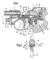
- Fig. 1 die erfindungswesentlichen Teile einer Gasdruckpistole im Längsschnitt und
- Fig. 2 im Querschnitt nach der Linie 11-11 der Fig. 1.
- Die Pistole weist ein allgemein mit 1 bezeichnetes Gehäuse auf, in dem der Lauf 2 befestigt und die Abzugvorrichtung 3 untergebracht ist. Am Stutzen 4 wird unterhalb des Laufes 2 ein Druckgasbehälter 5, insbesondere eine C02-Patrone, aufgeschraubt, dessen bzw. deren Ventil sich beim Aufschrauben öffnet, so daß das Druckgas in den Druckgasraum 6 gelangt, der durch ein Ventil 7 verschlossen ist. Fig. 1 zeigt die Stellung bei vom Laufhinterende zurückgezogenem Verschluß 8, der in einer Führung 9 gleitet. In dieser Stellung wird ein Geschoß, eine sogenannte Diabolokugel, in das Laufhinterende eingeführt, wonach der Verschluß 8 vorgeschoben wird, so daß das Laufhinterende damit abgschlossen und über einen Kanal 10 mit dem Ventil 7 verbunden ist.
- Die Abzugvorrichtung 3 besteht aus einem das Züngel 11 tragenden Abzughebel 12, der durch eine Feder 13 entgegen der Abzugrichtung beaufschlagt ist, ferner aus einem mit dem Abzughebel 12 zusammenwirkenden Abzugstollen 14 und einem Fanghebel 15, der mit dem Abzugstollen 14 verrastet ist und das durch eine Feder belastete Schlagstück 16 in der dargestellten Fangstellung zurückhält.
- Es ist ersichtlich, daß das Ventil 7 einen in einer Längsrippe 17 des Gehäuse 1 über das Züngel 11 hinaus nach hinten zum Schlagstück 16 geführten Schlagstift 18 aufweist und daß der Abzughebel 12 auf der Achse 19 oberhalb des Schlagstiftes 18 und knapp unterhalb der Führung 9 für den Verschluß 8 gelagert ist. Dabei läuft der Abzughebel 12 in zwei beiderseits der Längsrippe 17 liegende Seitenschenkel 12a aus.
- Wird das Züngel 11 entgegen dem Uhrzeigersinn bewegt, wird nach einem bestimmten Vorweg der Abzugstollen 14 verschwenkt, die Verrastung mitdem Fanghebel 15 wird gelöst und das Schlagstück 16 kann auf den Schlagstift 18 vorschnellen, so daß das Ventil 7 geöffnet und Druckgas hinter das in den Lauf 1 eingeführte Geschoß gelangt.
Claims (1)
Applications Claiming Priority (4)
| Application Number | Priority Date | Filing Date | Title |
|---|---|---|---|
| AT681/88 | 1988-03-04 | ||
| AT68188A AT391942B (de) | 1988-03-14 | 1988-03-14 | Schusswaffe, insbesondere pistole |
| AT165288A AT391945B (de) | 1988-06-27 | 1988-06-27 | Gasdruckpistole, insbesondere sportpistole |
| AT1652/88 | 1988-06-27 |
Publications (2)
| Publication Number | Publication Date |
|---|---|
| EP0333696A1 EP0333696A1 (de) | 1989-09-20 |
| EP0333696B1 true EP0333696B1 (de) | 1991-11-27 |
Family
ID=25593572
Family Applications (1)
| Application Number | Title | Priority Date | Filing Date |
|---|---|---|---|
| EP89890065A Expired - Lifetime EP0333696B1 (de) | 1988-03-14 | 1989-03-10 | Gasdruckpistole, insbesondere Sportpistole |
Country Status (5)
| Country | Link |
|---|---|
| US (1) | US4967724A (de) |
| EP (1) | EP0333696B1 (de) |
| CS (1) | CS275075B2 (de) |
| DE (1) | DE58900482D1 (de) |
| ES (1) | ES2028476T3 (de) |
Families Citing this family (12)
| Publication number | Priority date | Publication date | Assignee | Title |
|---|---|---|---|---|
| US5224465A (en) * | 1992-03-06 | 1993-07-06 | Crosman Corporation | Air gun with baffle for limiting maximum velocity |
| US7617628B2 (en) | 2004-12-22 | 2009-11-17 | Smith & Wesson Corp. | Fire control mechanism for a firearm |
| US7506469B2 (en) | 2004-12-22 | 2009-03-24 | Smith & Wesson Corp. | Firearm frame with configurable grip |
| US7472507B2 (en) | 2004-12-22 | 2009-01-06 | Smith & Wesson Corp. | Firearm with modular sear and trigger mechanism housings |
| US7703230B2 (en) | 2004-12-22 | 2010-04-27 | Smith & Wesson Corp. | Positive striker lock safety for use with a firearm |
| US7380362B2 (en) | 2004-12-22 | 2008-06-03 | Smith & Wesson Corp. | Firearm extractor mechanism |
| US7600340B2 (en) | 2004-12-22 | 2009-10-13 | Smith & Wesson Corp. | Locking apparatus for a firearm |
| US7389719B2 (en) | 2004-12-22 | 2008-06-24 | Smith & Wesson Corp. | Wire bushing for use with a firearm barrel |
| US7392611B2 (en) | 2004-12-22 | 2008-07-01 | Smith & Wesson Corp. | Apparatus and method for firearm takedown |
| RU2328690C1 (ru) * | 2006-10-06 | 2008-07-10 | Федеральное государственное унитарное предприятие "Ижевский механический завод" | Многозарядное пневматическое оружие |
| US8276302B2 (en) * | 2008-12-30 | 2012-10-02 | Smith & Wesson Corp. | Manual slide and hammer lock safety for a firearm |
| CN103638622B (zh) * | 2013-11-26 | 2015-09-16 | 浙江工业大学 | 高压气体脉冲水炮装置 |
Family Cites Families (12)
| Publication number | Priority date | Publication date | Assignee | Title |
|---|---|---|---|---|
| US1442864A (en) * | 1920-09-10 | 1923-01-23 | Declaye Joseph | Gunlock device of smallarms |
| US1854605A (en) * | 1930-06-16 | 1932-04-19 | Walter A Tratsch | Air gun |
| US2267078A (en) * | 1939-04-06 | 1941-12-23 | Western Cartridge Co | Firing mechanism for firearms |
| US2940438A (en) * | 1957-07-30 | 1960-06-14 | Crosman Arms Company Inc | Magazine gun |
| US3227148A (en) * | 1961-01-11 | 1966-01-04 | Benjamin Air Rifle Company | Gas operated gun |
| US3527194A (en) * | 1967-03-20 | 1970-09-08 | Crosman Arms Co Inc | Gas-powered pistol |
| NL137093C (de) * | 1968-07-08 | |||
| US3824981A (en) * | 1972-12-13 | 1974-07-23 | Crosman Arms Co Inc | Semi-automatic b-b pistol with trigger-connnected linkages |
| US4004566A (en) * | 1975-04-14 | 1977-01-25 | Minnesota Mining And Manufacturing Company | Clip and indexing mechanism for a gas-operated gun |
| US4336787A (en) * | 1980-07-21 | 1982-06-29 | Giacomo Cagnoni | Pre-compressed air weapon |
| DE3147068A1 (de) * | 1981-11-27 | 1983-06-09 | Feinwerkbau Westinger & Altenburger GmbH & Co KG, 7238 Oberndorf | Co(pfeil abwaerts)2(pfeil abwaerts)-waffe |
| DE3242102A1 (de) * | 1982-11-13 | 1984-05-17 | Carl Walther Gmbh, 7900 Ulm | Abzugseinrichtung fuer sportwaffen, insbesondere druckgasbetaetigte waffen |
-
1989
- 1989-02-27 US US07/316,473 patent/US4967724A/en not_active Expired - Fee Related
- 1989-03-10 ES ES198989890065T patent/ES2028476T3/es not_active Expired - Lifetime
- 1989-03-10 EP EP89890065A patent/EP0333696B1/de not_active Expired - Lifetime
- 1989-03-10 DE DE8989890065T patent/DE58900482D1/de not_active Expired - Fee Related
- 1989-03-14 CS CS891591A patent/CS275075B2/cs unknown
Non-Patent Citations (1)
| Title |
|---|
| "Feinwerkbau Bedienungsanleitung - Instructions Modell 2" * |
Also Published As
| Publication number | Publication date |
|---|---|
| DE58900482D1 (de) | 1992-01-09 |
| EP0333696A1 (de) | 1989-09-20 |
| US4967724A (en) | 1990-11-06 |
| ES2028476T3 (es) | 1992-07-01 |
| CS8901591A3 (en) | 1992-01-15 |
| CS275075B2 (en) | 1992-01-15 |
Similar Documents
| Publication | Publication Date | Title |
|---|---|---|
| EP1147359B1 (de) | Verschlussvorrichtung für eine handfeuerwaffe | |
| EP0071795B1 (de) | Automatische Handfeuerwaffe | |
| EP0416642A2 (de) | Feuerwaffe | |
| DE3033842A1 (de) | Gewehr | |
| DE102006006034B3 (de) | Handfeuerwaffe mit Durchladehebel | |
| EP0333696B1 (de) | Gasdruckpistole, insbesondere Sportpistole | |
| DE19529483C1 (de) | Selbstladegewehr mit Schwenklauf | |
| WO2005108900A1 (de) | Selbstlade-handfeuerwaffe mit beschleunigtem verschlussträger | |
| EP0085193A1 (de) | Granaten-Abschusseinrichtung zum Anbau an Gewehre | |
| EP4180758B1 (de) | Schloss einer jagd- oder sportwaffe mit sicherungseinrichtungen | |
| DE19629978A1 (de) | Kabellose Laserpistole | |
| DE3035796C2 (de) | ||
| AT391945B (de) | Gasdruckpistole, insbesondere sportpistole | |
| DE3522155C2 (de) | Faustfeuerwaffe | |
| DE69613396T2 (de) | Unterwasserpistole für sportzwecke | |
| DE1166052B (de) | Einsatzgeraet mit Einstecklauf zum Verschiessen von Kleinkaliber-Munition durch automatische Handfeuerwaffen, insbesondere Sturmgewehre mit Hammerzuendung | |
| DE727603C (de) | Selbsttaetige Schusswaffe | |
| AT403523B (de) | Druckgasbetriebene schusswaffe, insbesondere sportwaffe | |
| DD283680A5 (de) | Gasdruckpistole, insbesondere sportpistole | |
| DE570117C (de) | Einschuessige Schreckschusspistole mit selbsttaetigem Patronenauswurf und sich gleichzeitig selbstspannendem Hahn | |
| DE19839986A1 (de) | Druckgaswaffe mit Rückstoßausgleich | |
| CH216705A (de) | Abzugseinrichtung für in einer Lafette verwendbare selbsttätige Schulterwaffen. | |
| DE69311379T2 (de) | Doppelläufige kipplaufwaffe grossen kalibers | |
| DE10034114C1 (de) | Spielzeugschießwaffe | |
| DE809154C (de) | Repetierfeuerwaffe |
Legal Events
| Date | Code | Title | Description |
|---|---|---|---|
| PUAI | Public reference made under article 153(3) epc to a published international application that has entered the european phase |
Free format text: ORIGINAL CODE: 0009012 |
|
| AK | Designated contracting states |
Kind code of ref document: A1 Designated state(s): BE CH DE ES FR GB IT LI NL SE |
|
| 17P | Request for examination filed |
Effective date: 19890803 |
|
| 17Q | First examination report despatched |
Effective date: 19901203 |
|
| ITF | It: translation for a ep patent filed | ||
| GRAA | (expected) grant |
Free format text: ORIGINAL CODE: 0009210 |
|
| AK | Designated contracting states |
Kind code of ref document: B1 Designated state(s): BE CH DE ES FR GB IT LI NL SE |
|
| GBT | Gb: translation of ep patent filed (gb section 77(6)(a)/1977) | ||
| REF | Corresponds to: |
Ref document number: 58900482 Country of ref document: DE Date of ref document: 19920109 |
|
| ET | Fr: translation filed | ||
| REG | Reference to a national code |
Ref country code: ES Ref legal event code: FG2A Ref document number: 2028476 Country of ref document: ES Kind code of ref document: T3 |
|
| PLBE | No opposition filed within time limit |
Free format text: ORIGINAL CODE: 0009261 |
|
| STAA | Information on the status of an ep patent application or granted ep patent |
Free format text: STATUS: NO OPPOSITION FILED WITHIN TIME LIMIT |
|
| 26N | No opposition filed | ||
| EAL | Se: european patent in force in sweden |
Ref document number: 89890065.9 |
|
| PGFP | Annual fee paid to national office [announced via postgrant information from national office to epo] |
Ref country code: GB Payment date: 19960215 Year of fee payment: 8 |
|
| PGFP | Annual fee paid to national office [announced via postgrant information from national office to epo] |
Ref country code: SE Payment date: 19960219 Year of fee payment: 8 |
|
| PGFP | Annual fee paid to national office [announced via postgrant information from national office to epo] |
Ref country code: FR Payment date: 19960220 Year of fee payment: 8 Ref country code: BE Payment date: 19960220 Year of fee payment: 8 |
|
| PGFP | Annual fee paid to national office [announced via postgrant information from national office to epo] |
Ref country code: NL Payment date: 19960222 Year of fee payment: 8 |
|
| PGFP | Annual fee paid to national office [announced via postgrant information from national office to epo] |
Ref country code: ES Payment date: 19960321 Year of fee payment: 8 |
|
| PG25 | Lapsed in a contracting state [announced via postgrant information from national office to epo] |
Ref country code: GB Effective date: 19970310 |
|
| PG25 | Lapsed in a contracting state [announced via postgrant information from national office to epo] |
Ref country code: SE Effective date: 19970311 Ref country code: ES Free format text: LAPSE BECAUSE OF NON-PAYMENT OF DUE FEES Effective date: 19970311 |
|
| PG25 | Lapsed in a contracting state [announced via postgrant information from national office to epo] |
Ref country code: BE Effective date: 19970331 |
|
| BERE | Be: lapsed |
Owner name: STEYR-DAIMLER-PUCH A.G. Effective date: 19970331 |
|
| PG25 | Lapsed in a contracting state [announced via postgrant information from national office to epo] |
Ref country code: NL Effective date: 19971001 |
|
| GBPC | Gb: european patent ceased through non-payment of renewal fee |
Effective date: 19970310 |
|
| PG25 | Lapsed in a contracting state [announced via postgrant information from national office to epo] |
Ref country code: FR Free format text: LAPSE BECAUSE OF NON-PAYMENT OF DUE FEES Effective date: 19971128 |
|
| NLV4 | Nl: lapsed or anulled due to non-payment of the annual fee |
Effective date: 19971001 |
|
| EUG | Se: european patent has lapsed |
Ref document number: 89890065.9 |
|
| REG | Reference to a national code |
Ref country code: FR Ref legal event code: ST |
|
| REG | Reference to a national code |
Ref country code: ES Ref legal event code: FD2A Effective date: 19990405 |
|
| PGFP | Annual fee paid to national office [announced via postgrant information from national office to epo] |
Ref country code: CH Payment date: 20020225 Year of fee payment: 14 |
|
| PG25 | Lapsed in a contracting state [announced via postgrant information from national office to epo] |
Ref country code: LI Free format text: LAPSE BECAUSE OF NON-PAYMENT OF DUE FEES Effective date: 20030331 Ref country code: CH Free format text: LAPSE BECAUSE OF NON-PAYMENT OF DUE FEES Effective date: 20030331 |
|
| REG | Reference to a national code |
Ref country code: CH Ref legal event code: PL |
|
| PG25 | Lapsed in a contracting state [announced via postgrant information from national office to epo] |
Ref country code: IT Free format text: LAPSE BECAUSE OF NON-PAYMENT OF DUE FEES;WARNING: LAPSES OF ITALIAN PATENTS WITH EFFECTIVE DATE BEFORE 2007 MAY HAVE OCCURRED AT ANY TIME BEFORE 2007. THE CORRECT EFFECTIVE DATE MAY BE DIFFERENT FROM THE ONE RECORDED. Effective date: 20050310 |
|
| PGFP | Annual fee paid to national office [announced via postgrant information from national office to epo] |
Ref country code: DE Payment date: 20060530 Year of fee payment: 18 |
|
| PG25 | Lapsed in a contracting state [announced via postgrant information from national office to epo] |
Ref country code: DE Free format text: LAPSE BECAUSE OF NON-PAYMENT OF DUE FEES Effective date: 20071002 |